EP0937603B1 - Dispositif de verrouillage pour un dossier rabattable de véhicule automobile - Google Patents
Dispositif de verrouillage pour un dossier rabattable de véhicule automobile Download PDFInfo
- Publication number
- EP0937603B1 EP0937603B1 EP99102108A EP99102108A EP0937603B1 EP 0937603 B1 EP0937603 B1 EP 0937603B1 EP 99102108 A EP99102108 A EP 99102108A EP 99102108 A EP99102108 A EP 99102108A EP 0937603 B1 EP0937603 B1 EP 0937603B1
- Authority
- EP
- European Patent Office
- Prior art keywords
- backrest
- locking
- seat
- hole
- component fixed
- Prior art date
- Legal status (The legal status is an assumption and is not a legal conclusion. Google has not performed a legal analysis and makes no representation as to the accuracy of the status listed.)
- Expired - Lifetime
Links
- 230000006835 compression Effects 0.000 description 8
- 238000007906 compression Methods 0.000 description 8
- 238000010276 construction Methods 0.000 description 3
- 238000005516 engineering process Methods 0.000 description 2
- 230000001419 dependent effect Effects 0.000 description 1
- 238000006073 displacement reaction Methods 0.000 description 1
- 230000001404 mediated effect Effects 0.000 description 1
- 238000000034 method Methods 0.000 description 1
Images

Classifications
-
- B—PERFORMING OPERATIONS; TRANSPORTING
- B60—VEHICLES IN GENERAL
- B60N—SEATS SPECIALLY ADAPTED FOR VEHICLES; VEHICLE PASSENGER ACCOMMODATION NOT OTHERWISE PROVIDED FOR
- B60N2/00—Seats specially adapted for vehicles; Arrangement or mounting of seats in vehicles
- B60N2/02—Seats specially adapted for vehicles; Arrangement or mounting of seats in vehicles the seat or part thereof being movable, e.g. adjustable
- B60N2/20—Seats specially adapted for vehicles; Arrangement or mounting of seats in vehicles the seat or part thereof being movable, e.g. adjustable the back-rest being tiltable, e.g. to permit easy access
-
- B—PERFORMING OPERATIONS; TRANSPORTING
- B60—VEHICLES IN GENERAL
- B60N—SEATS SPECIALLY ADAPTED FOR VEHICLES; VEHICLE PASSENGER ACCOMMODATION NOT OTHERWISE PROVIDED FOR
- B60N2/00—Seats specially adapted for vehicles; Arrangement or mounting of seats in vehicles
- B60N2/24—Seats specially adapted for vehicles; Arrangement or mounting of seats in vehicles for particular purposes or particular vehicles
- B60N2/42—Seats specially adapted for vehicles; Arrangement or mounting of seats in vehicles for particular purposes or particular vehicles the seat constructed to protect the occupant from the effect of abnormal g-forces, e.g. crash or safety seats
- B60N2/433—Safety locks for back-rests, e.g. with locking bars activated by inertia
Definitions
- the present invention relates to a locking device for a foldable backrest of a motor vehicle seat according to the preamble of independent claim 1 (see e.g. DE 1 505 503 A).
- the backrest is usually in a motor vehicle seat adjustable in inclination relative to the seat part to the Backrest of different body sizes and seating habits optimally adapt. Regardless of this inclination setting the backrest is at the relevant level here Technology stored on the seat part between two end positions.
- the backrest In a first setting, the so-called position of use, the backrest is swung back and against it Fold down locked in front. After releasing a lock the backrest can be folded down by hand in the direction of travel, until the upper end of the backrest abuts the steering wheel.
- This solution is particularly advantageous for two-door cars, to make it easier for people to get into the rear.
- the locking devices for foldable backrests must be crash-proof in order to prevent the Avoid backrests in the event of an accident.
- According to the state of the Technology are usually hook-shaped latches for locking used, basically between two solution principles is to be distinguished.
- the pawls are arranged transversely to the direction of travel.
- This and other constructions with transverse to the direction of travel Pivot axes of the pawls have the disadvantage that in the event of a crash very large forces act on the pawls, so that special precautions must be taken to the locking position of the Secure pawls.
- a second solution variant known from the prior art assumes the pivot axes of the pawls in the direction of travel to arrange. Such a solution is in DE 196 27 853 A1. Because of this alignment of the swivel axes the jacks remain in place even in the event of a crash without additional safety devices in the locked position. In the latter group is also the subject of the present invention.
- From DE-Gm 69 08 021 is a vehicle seat with one in the Adjustable backrest known.
- the backrest is on side arms fixed to the seat part on both sides pivoted, with a rigid on one side of the seat Backrest frame connected adjusting lever is arranged.
- At the The lower end of this adjustment lever has several locking holes provided with a transverse to the in the adjacent side arm Interact with the locking bolts guided in the direction of travel.
- the locking pin is biased to the locking holes and has one Handle knob.
- the locking bolt is made using this handle knob pulled out one of the locking holes, the backrest in adjusted their inclination and the desired inclination by snapping the locking bolt locked in a corresponding locking hole become.
- a generic locking device is the above. DE 1 505 503 A.
- This locking device has a locking bolt that can be moved transversely to the direction of travel, which is stored in a backrest-fixed component and in the locked position a corresponding hole in a seat part fixed Reaches through the component without play.
- This locking device is door operated. When the door closes, it presses the bolt into its locked position while it is in the opening process of the door under the action of the lock comes free.
- the object of the present invention is a further locking device of the type mentioned at the beginning to deliver.
- the solution according to the invention provides for the use of the State of the art used for locking hook-shaped Paw off by a locking bolt that can be moved transversely to the direction of travel is proposed.
- This locking bolt is a game-free and crash-proof in a very simple way Locking the backrest-fixed component to the seat part Realizable component.
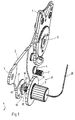
- the backrest of which only a cut in Fig. 1 Area of a side member 1 is shown, is on both Seat sides foldable via adapter 2 on the seat frame, not shown supported.
- the adapter 2 have on their front End a hole 3, which form the backrest folding points. These holes 3 take seat part fixed bolts, which is not is shown.
- Fig. 1 the direction of travel is by a Arrow 4 indicated.
- the adapter 2 is via a rotary adjuster 5 with the side rail 1 of the backrest connected.
- This rotary adjuster 5 is executed according to the prior art, so that further discussions to spare.
- With the backrest in the position of use is the bottom 6 of the adapter 2 on a seat part fixed Stop 7 on.
- a locking device must be prevented 8 provided, the structure of which is based on of two exemplary embodiments according to FIGS. 2 and 3 explained in more detail becomes.
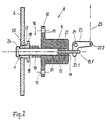
- the locking device 8 has a guide bush 9 on the inside of the not shown Seat frame is flanged. For this it is with a flange 10 and through holes 11 for fastening screws.
- the guide bush 9 has a central through hole 13, which at the end facing the inside of the seat a collar 14 is narrowed to a smaller diameter.
- the shaft 15 is one with the reference numeral 16 provided locking bolt transverse to Direction of travel 4 (Fig. 1) performed.
- This locking bolt 16th further consists of a cone bushing 17 on the shaft 15 is mounted for longitudinal displacement.
- the cone bushing 17 has a flange 18. Between this Flange 18 and the flange 10 of the guide bush 9 is concentric to the shaft 15 a compression spring 19 inserted, the cone bushing 17 on a conical hole 20 corresponding to this preloaded in adapter 2. The reaches through in the locked position Cone bushing 17, the cone hole 20, the two cone surfaces ensure a backlash-free system.
- the movement of the shaft 15 to the left is limited by an angle lever 23, one leg 23.1 into the end of the section protruding from the guide bushing 9 15.1 is attached.
- the angle lever 23 is on one Bolt 24 fixed to the seat part is pivotally mounted.
- his other Leg 23.2 is a pull rope 25 leading to the backrest folding lever hooked.
- the backrest folding lever is in the locked position on one Stop on, whereby the position of the Angle lever 23, mediated by the pull rope 25, is fixed - in other words, the one applied by the compression spring 22 Shaft 15 of the locking bolt 16 is prevented from itself move further to the left.
- leg 23.1 of the angle lever 23 is shorter than the other leg 23.2. This "built-in" Although the translation extends the actuation path of the backrest folding lever, but reduces its operating force in the desired manner.
- the cone bushing is on 17 associated end of the shaft 15 a head 26 is formed, whose diameter is larger than the inside diameter of the Cone bushing 17, but smaller than the smallest diameter of the cone hole 20 is. Between this head 26 and the one facing it End face of the cone bushing 17 is in the locking position a game x exists. This game x ensures that the cone bushing 17 in the locking position without play on the Wall of the conical hole 20 is present. It therefore serves to compensate for tolerances.
- the locking device 8 described works as follows:
- the backrest folding lever After the backrest is folded forward, the backrest folding lever usually let go.
- the compression springs 22 and 19 then press the shaft 15 and thus its head 26 against the Adapter surface. Slides when the backrest is folded back the head 26 on the adapter 2 until it dips into the cone hole 20.
- the compression spring 22 then presses the shaft 15 further left into the position shown in FIG. 2. simultaneously the compression spring 19 pushes the cone bushing 17 on the shaft 15 in engagement with the conical hole 20.
- the adapter is in place 2 again with its underside 6 on the seat part fixed Stop 7 on.
- the backrest is now free of play again locked.
- FIG. 3 is another embodiment of a locking device 8 shown.
- the only difference from that variant previously explained is that the pull rope 25 directly tied to the shaft 15 of the locking bolt 16 is.
- the operation of this locking device 8 is otherwise identical to that of the previous embodiment, so that another explanation is not necessary at this point is.
- the locking device shown in Fig. 3 8 corresponds to that of FIG. 1.
Landscapes
- Engineering & Computer Science (AREA)
- Aviation & Aerospace Engineering (AREA)
- Transportation (AREA)
- Mechanical Engineering (AREA)
- Seats For Vehicles (AREA)
- Chairs For Special Purposes, Such As Reclining Chairs (AREA)
Claims (2)
- Dispositif de verrouillage pour un dossier articulé d'un siège de véhicule automobile, dont un composant monté fixe sur le siège et un composant monté fixe sur le dossier peuvent être verrouillés l'un sur l'autre, de manière amovible, transversalement à la direction de roulement en position d'utilisation du dossier, un verrou (16) déplaçable transversalement à la direction de roulement étant prévu pour le verrouillage, verrou qui est logé dans le composant monté fixe sur le siège ou dans le composant monté fixe sur le dossier et qui, en position de verrouillage, traverse, sans laisser de jeu, un trou correspondant (20) pratiqué dans le composant fixe du dossier ou dans le composant fixe du siège, caractérisé en ce que la paroi du trou (20) est conique et qu'une douille conique (17) est guidée déplaçable sur une tige (15) du verrou (16), douille conique qui est précontrainte sur l'extrémité de la tige (15) et qui, en position de verrouillage, s'avance dans le trou (20) sans laisser de jeu, la tige (15) étant pourvue, à son extrémité tournée vers le trou (20), d'une tête (26) dont les dimensions radiales sont plus importantes que le diamètre intérieur de la douille conique (17), mais plus petites que le plus petit diamètre du trou (20), qu'en position de verrouillage, un jeu (x) existe entre la tête (26) et l'extrémité tournée vers celle-ci de la douille conique, la tête (26) servant, pendant le processus de déverrouillage, d'élément d'entraínement à la douille conique (17).
- Dispositif de verrouillage suivant la revendication 1, caractérisé en ce que la tige (15) du verrou (16) est précontrainte en position de verrouillage et reliée, pour le déverrouillage, à un câble tracteur (25).
Applications Claiming Priority (2)
| Application Number | Priority Date | Filing Date | Title |
|---|---|---|---|
| DE19806904A DE19806904C1 (de) | 1998-02-19 | 1998-02-19 | Verriegelungsvorrichtung für eine klappbare Rückenlehne eines Kraftfahrzeugsitzes |
| DE19806904 | 1998-02-19 |
Publications (2)
| Publication Number | Publication Date |
|---|---|
| EP0937603A1 EP0937603A1 (fr) | 1999-08-25 |
| EP0937603B1 true EP0937603B1 (fr) | 2002-07-03 |
Family
ID=7858253
Family Applications (1)
| Application Number | Title | Priority Date | Filing Date |
|---|---|---|---|
| EP99102108A Expired - Lifetime EP0937603B1 (fr) | 1998-02-19 | 1999-02-03 | Dispositif de verrouillage pour un dossier rabattable de véhicule automobile |
Country Status (2)
| Country | Link |
|---|---|
| EP (1) | EP0937603B1 (fr) |
| DE (2) | DE19806904C1 (fr) |
Families Citing this family (5)
| Publication number | Priority date | Publication date | Assignee | Title |
|---|---|---|---|---|
| DE19953686C1 (de) * | 1999-11-09 | 2001-08-23 | Keiper Gmbh & Co | Beschlag für die Rückenlehne von Fahrzeugsitzen, insbesondere von Kraftfahrzeugen |
| DE10054432A1 (de) * | 2000-10-26 | 2002-05-02 | Volkswagen Ag | Fahrzeugsitz mit einem Sitzteil und einer Rückenlehne, insbesondere für ein Kraftfahrzeug |
| FR2816260B1 (fr) * | 2000-11-08 | 2003-02-07 | Faurecia Sieges Automobile | Mecanisme de pivotement pour siege de vehicule et siege comportant ce mecanisme |
| FR2883520B1 (fr) * | 2005-03-22 | 2008-10-10 | Faurecia Sieges Automobile | Siege de vehicule comportant un dossier rabattable vers l'avant. |
| DE102013222537B4 (de) * | 2013-11-06 | 2021-06-17 | Brose Fahrzeugteile SE & Co. Kommanditgesellschaft, Coburg | Fahrzeugsitz mit einer Durchführung für ein Zugmittel |
Family Cites Families (7)
| Publication number | Priority date | Publication date | Assignee | Title |
|---|---|---|---|---|
| DE1770885U (de) * | 1958-05-13 | 1958-07-24 | Franz Kiel G M B H | Vorrichtung zum festlegen von gegeneinander verstellbaren sitzteilen. |
| DE1505503A1 (de) * | 1965-12-10 | 1969-10-23 | Ernst Beck | Tuerbetaetigte automatische Sitzverriegelung |
| US3339976A (en) * | 1966-05-12 | 1967-09-05 | Karl Robert | Automobile seat backrest locking device |
| DE6908021U (de) * | 1969-02-28 | 1969-06-19 | Isringhausen Fa Geb | Fahrzeugsitz mit rueckenlehnenverstellung |
| FR2087549A5 (fr) * | 1970-05-22 | 1971-12-31 | Cousin Cie Ets A & M Freres | |
| DE4417491C2 (de) * | 1994-05-19 | 1999-07-15 | Keiper Gmbh & Co | Fanghaken zur lösbaren Verriegelung der mit dem Sitzteil eines Fahrzeugsitzes vorschwenkbar verbundenen Rückenlehne |
| DE19627853C2 (de) * | 1996-07-11 | 1999-07-22 | Faure Bertrand Sitztech Gmbh | Verriegelungsvorrichtung für eine schwenkbare Rückenlehne eines Kraftfahrzeugsitzes |
-
1998
- 1998-02-19 DE DE19806904A patent/DE19806904C1/de not_active Expired - Fee Related
-
1999
- 1999-02-03 EP EP99102108A patent/EP0937603B1/fr not_active Expired - Lifetime
- 1999-02-03 DE DE59901888T patent/DE59901888D1/de not_active Expired - Fee Related
Also Published As
| Publication number | Publication date |
|---|---|
| EP0937603A1 (fr) | 1999-08-25 |
| DE19806904C1 (de) | 1999-09-09 |
| DE59901888D1 (de) | 2002-08-08 |
Similar Documents
| Publication | Publication Date | Title |
|---|---|---|
| EP0671292B1 (fr) | Siège arrière de véhicule automobile à dossier en deux parties | |
| DE69406718T2 (de) | Mehrfachsitz für Kraftfahrzeuge | |
| EP1474308A1 (fr) | Dispositif de reglage en longueur d'un siege de vehicule | |
| DE10050735A1 (de) | Flach umklappbarer Fahrzeugsitz | |
| WO2004069580A2 (fr) | Dispositif de verrouillage pour siège de véhicule | |
| DE102013215028B4 (de) | Easy-Entry-System für einen Fahrzeugsitz und Fahrzeugsitz | |
| WO2014075819A1 (fr) | Siège de véhicule, en particulier siège de véhicule automobile | |
| EP1334005A1 (fr) | Siege de vehicule | |
| EP1107878B1 (fr) | Dispositif de fixation pour siege enfant | |
| DE69700556T2 (de) | Nach vorn bewegbarer Fahrzeugsitz, um zu einem hinteren Raum zu gelangen | |
| DE4417491C2 (de) | Fanghaken zur lösbaren Verriegelung der mit dem Sitzteil eines Fahrzeugsitzes vorschwenkbar verbundenen Rückenlehne | |
| EP0994789A1 (fr) | Dispositif de fixation d'un siege enfant sur un siege de vehicule | |
| EP1048509B1 (fr) | Siège de voiture automobile | |
| DE102015221077A1 (de) | Längseinsteller für einen fahrzeugsitz, fahrzeugsitz | |
| DE10163611A1 (de) | Entriegelungsvorrichtung für einen Fahrzeugsitz | |
| EP2004448B1 (fr) | Systeme de deplacement d'un siege de vehicule | |
| DE10238487A1 (de) | Fahrzeugsitz | |
| DE19806904C1 (de) | Verriegelungsvorrichtung für eine klappbare Rückenlehne eines Kraftfahrzeugsitzes | |
| DE10043923A1 (de) | Fahrzeugsitz mit Kopfstütze | |
| DE10145240A1 (de) | Kopfstütze für Fahrzeugsitze | |
| EP1259395B1 (fr) | Dispositif de reglage de dossiers de sieges de vehicules, notamment de vehicules automobiles | |
| EP3290261A1 (fr) | Dispositif de reglage en longueur de siege de vehicule et siege de vehicule | |
| DE20302007U1 (de) | Verriegelungsvorrichtung für einen Fahrzeugsitz | |
| DE10052090C1 (de) | Entriegelungsmechanik für einen Fahrzeugsitz | |
| EP0921029B1 (fr) | Siège de véhicule à dossier rabattable |
Legal Events
| Date | Code | Title | Description |
|---|---|---|---|
| PUAI | Public reference made under article 153(3) epc to a published international application that has entered the european phase |
Free format text: ORIGINAL CODE: 0009012 |
|
| 17P | Request for examination filed |
Effective date: 19990604 |
|
| AK | Designated contracting states |
Kind code of ref document: A1 Designated state(s): DE FR GB IT |
|
| AX | Request for extension of the european patent |
Free format text: AL;LT;LV;MK;RO;SI |
|
| AKX | Designation fees paid |
Free format text: DE FR GB IT |
|
| 17Q | First examination report despatched |
Effective date: 20010629 |
|
| GRAG | Despatch of communication of intention to grant |
Free format text: ORIGINAL CODE: EPIDOS AGRA |
|
| GRAG | Despatch of communication of intention to grant |
Free format text: ORIGINAL CODE: EPIDOS AGRA |
|
| GRAH | Despatch of communication of intention to grant a patent |
Free format text: ORIGINAL CODE: EPIDOS IGRA |
|
| GRAG | Despatch of communication of intention to grant |
Free format text: ORIGINAL CODE: EPIDOS AGRA |
|
| GRAH | Despatch of communication of intention to grant a patent |
Free format text: ORIGINAL CODE: EPIDOS IGRA |
|
| GRAH | Despatch of communication of intention to grant a patent |
Free format text: ORIGINAL CODE: EPIDOS IGRA |
|
| RAP1 | Party data changed (applicant data changed or rights of an application transferred) |
Owner name: FAURECIA AUTOSITZE GMBH & CO. KG |
|
| GRAA | (expected) grant |
Free format text: ORIGINAL CODE: 0009210 |
|
| AK | Designated contracting states |
Kind code of ref document: B1 Designated state(s): DE FR GB IT |
|
| REF | Corresponds to: |
Ref document number: 59901888 Country of ref document: DE Date of ref document: 20020808 |
|
| GBT | Gb: translation of ep patent filed (gb section 77(6)(a)/1977) |
Effective date: 20021003 |
|
| ET | Fr: translation filed | ||
| PGFP | Annual fee paid to national office [announced via postgrant information from national office to epo] |
Ref country code: DE Payment date: 20030424 Year of fee payment: 5 |
|
| PLBE | No opposition filed within time limit |
Free format text: ORIGINAL CODE: 0009261 |
|
| STAA | Information on the status of an ep patent application or granted ep patent |
Free format text: STATUS: NO OPPOSITION FILED WITHIN TIME LIMIT |
|
| 26N | No opposition filed |
Effective date: 20030404 |
|
| PG25 | Lapsed in a contracting state [announced via postgrant information from national office to epo] |
Ref country code: DE Free format text: LAPSE BECAUSE OF NON-PAYMENT OF DUE FEES Effective date: 20040901 |
|
| PGFP | Annual fee paid to national office [announced via postgrant information from national office to epo] |
Ref country code: IT Payment date: 20080220 Year of fee payment: 10 Ref country code: GB Payment date: 20080219 Year of fee payment: 10 |
|
| PGFP | Annual fee paid to national office [announced via postgrant information from national office to epo] |
Ref country code: FR Payment date: 20080215 Year of fee payment: 10 |
|
| GBPC | Gb: european patent ceased through non-payment of renewal fee |
Effective date: 20090203 |
|
| REG | Reference to a national code |
Ref country code: FR Ref legal event code: ST Effective date: 20091030 |
|
| PG25 | Lapsed in a contracting state [announced via postgrant information from national office to epo] |
Ref country code: GB Free format text: LAPSE BECAUSE OF NON-PAYMENT OF DUE FEES Effective date: 20090203 Ref country code: FR Free format text: LAPSE BECAUSE OF NON-PAYMENT OF DUE FEES Effective date: 20090302 |
|
| PG25 | Lapsed in a contracting state [announced via postgrant information from national office to epo] |
Ref country code: IT Free format text: LAPSE BECAUSE OF NON-PAYMENT OF DUE FEES Effective date: 20090203 |