EP0937620A2 - Method and device for controlling a brake system - Google Patents
Method and device for controlling a brake system Download PDFInfo
- Publication number
- EP0937620A2 EP0937620A2 EP98118433A EP98118433A EP0937620A2 EP 0937620 A2 EP0937620 A2 EP 0937620A2 EP 98118433 A EP98118433 A EP 98118433A EP 98118433 A EP98118433 A EP 98118433A EP 0937620 A2 EP0937620 A2 EP 0937620A2
- Authority
- EP
- European Patent Office
- Prior art keywords
- pressure
- wheel
- error
- brake
- wheel brake
- Prior art date
- Legal status (The legal status is an assumption and is not a legal conclusion. Google has not performed a legal analysis and makes no representation as to the accuracy of the status listed.)
- Granted
Links
- 238000000034 method Methods 0.000 title claims abstract description 15
- 230000001276 controlling effect Effects 0.000 claims description 10
- 230000006870 function Effects 0.000 claims description 5
- 230000001105 regulatory effect Effects 0.000 claims description 5
- 230000009467 reduction Effects 0.000 claims description 4
- 210000003205 muscle Anatomy 0.000 claims description 3
- 230000000717 retained effect Effects 0.000 claims 1
- 230000001419 dependent effect Effects 0.000 abstract description 4
- 238000001514 detection method Methods 0.000 abstract description 3
- 230000004913 activation Effects 0.000 abstract 1
- 238000012544 monitoring process Methods 0.000 description 6
- 230000008859 change Effects 0.000 description 3
- 230000000694 effects Effects 0.000 description 3
- 238000002955 isolation Methods 0.000 description 2
- 230000009471 action Effects 0.000 description 1
- 230000000712 assembly Effects 0.000 description 1
- 238000000429 assembly Methods 0.000 description 1
- 230000006399 behavior Effects 0.000 description 1
- 230000015572 biosynthetic process Effects 0.000 description 1
- 230000007547 defect Effects 0.000 description 1
- 230000002950 deficient Effects 0.000 description 1
- 238000010586 diagram Methods 0.000 description 1
- 238000006073 displacement reaction Methods 0.000 description 1
- 239000012530 fluid Substances 0.000 description 1
- 230000006872 improvement Effects 0.000 description 1
- 230000008569 process Effects 0.000 description 1
Images

Classifications
-
- B—PERFORMING OPERATIONS; TRANSPORTING
- B60—VEHICLES IN GENERAL
- B60T—VEHICLE BRAKE CONTROL SYSTEMS OR PARTS THEREOF; BRAKE CONTROL SYSTEMS OR PARTS THEREOF, IN GENERAL; ARRANGEMENT OF BRAKING ELEMENTS ON VEHICLES IN GENERAL; PORTABLE DEVICES FOR PREVENTING UNWANTED MOVEMENT OF VEHICLES; VEHICLE MODIFICATIONS TO FACILITATE COOLING OF BRAKES
- B60T17/00—Component parts, details, or accessories of power brake systems not covered by groups B60T8/00, B60T13/00 or B60T15/00, or presenting other characteristic features
- B60T17/18—Safety devices; Monitoring
- B60T17/22—Devices for monitoring or checking brake systems; Signal devices
- B60T17/221—Procedure or apparatus for checking or keeping in a correct functioning condition of brake systems
-
- B—PERFORMING OPERATIONS; TRANSPORTING
- B60—VEHICLES IN GENERAL
- B60T—VEHICLE BRAKE CONTROL SYSTEMS OR PARTS THEREOF; BRAKE CONTROL SYSTEMS OR PARTS THEREOF, IN GENERAL; ARRANGEMENT OF BRAKING ELEMENTS ON VEHICLES IN GENERAL; PORTABLE DEVICES FOR PREVENTING UNWANTED MOVEMENT OF VEHICLES; VEHICLE MODIFICATIONS TO FACILITATE COOLING OF BRAKES
- B60T13/00—Transmitting braking action from initiating means to ultimate brake actuator with power assistance or drive; Brake systems incorporating such transmitting means, e.g. air-pressure brake systems
- B60T13/10—Transmitting braking action from initiating means to ultimate brake actuator with power assistance or drive; Brake systems incorporating such transmitting means, e.g. air-pressure brake systems with fluid assistance, drive, or release
- B60T13/66—Electrical control in fluid-pressure brake systems
- B60T13/68—Electrical control in fluid-pressure brake systems by electrically-controlled valves
- B60T13/686—Electrical control in fluid-pressure brake systems by electrically-controlled valves in hydraulic systems or parts thereof
-
- B—PERFORMING OPERATIONS; TRANSPORTING
- B60—VEHICLES IN GENERAL
- B60T—VEHICLE BRAKE CONTROL SYSTEMS OR PARTS THEREOF; BRAKE CONTROL SYSTEMS OR PARTS THEREOF, IN GENERAL; ARRANGEMENT OF BRAKING ELEMENTS ON VEHICLES IN GENERAL; PORTABLE DEVICES FOR PREVENTING UNWANTED MOVEMENT OF VEHICLES; VEHICLE MODIFICATIONS TO FACILITATE COOLING OF BRAKES
- B60T7/00—Brake-action initiating means
- B60T7/02—Brake-action initiating means for personal initiation
- B60T7/04—Brake-action initiating means for personal initiation foot actuated
- B60T7/042—Brake-action initiating means for personal initiation foot actuated by electrical means, e.g. using travel or force sensors
-
- B—PERFORMING OPERATIONS; TRANSPORTING
- B60—VEHICLES IN GENERAL
- B60T—VEHICLE BRAKE CONTROL SYSTEMS OR PARTS THEREOF; BRAKE CONTROL SYSTEMS OR PARTS THEREOF, IN GENERAL; ARRANGEMENT OF BRAKING ELEMENTS ON VEHICLES IN GENERAL; PORTABLE DEVICES FOR PREVENTING UNWANTED MOVEMENT OF VEHICLES; VEHICLE MODIFICATIONS TO FACILITATE COOLING OF BRAKES
- B60T8/00—Arrangements for adjusting wheel-braking force to meet varying vehicular or ground-surface conditions, e.g. limiting or varying distribution of braking force
- B60T8/32—Arrangements for adjusting wheel-braking force to meet varying vehicular or ground-surface conditions, e.g. limiting or varying distribution of braking force responsive to a speed condition, e.g. acceleration or deceleration
- B60T8/34—Arrangements for adjusting wheel-braking force to meet varying vehicular or ground-surface conditions, e.g. limiting or varying distribution of braking force responsive to a speed condition, e.g. acceleration or deceleration having a fluid pressure regulator responsive to a speed condition
- B60T8/40—Arrangements for adjusting wheel-braking force to meet varying vehicular or ground-surface conditions, e.g. limiting or varying distribution of braking force responsive to a speed condition, e.g. acceleration or deceleration having a fluid pressure regulator responsive to a speed condition comprising an additional fluid circuit including fluid pressurising means for modifying the pressure of the braking fluid, e.g. including wheel driven pumps for detecting a speed condition, or pumps which are controlled by means independent of the braking system
- B60T8/4072—Systems in which a driver input signal is used as a control signal for the additional fluid circuit which is normally used for braking
- B60T8/4081—Systems with stroke simulating devices for driver input
- B60T8/4086—Systems with stroke simulating devices for driver input the stroke simulating device being connected to, or integrated in the driver input device
-
- B—PERFORMING OPERATIONS; TRANSPORTING
- B60—VEHICLES IN GENERAL
- B60T—VEHICLE BRAKE CONTROL SYSTEMS OR PARTS THEREOF; BRAKE CONTROL SYSTEMS OR PARTS THEREOF, IN GENERAL; ARRANGEMENT OF BRAKING ELEMENTS ON VEHICLES IN GENERAL; PORTABLE DEVICES FOR PREVENTING UNWANTED MOVEMENT OF VEHICLES; VEHICLE MODIFICATIONS TO FACILITATE COOLING OF BRAKES
- B60T8/00—Arrangements for adjusting wheel-braking force to meet varying vehicular or ground-surface conditions, e.g. limiting or varying distribution of braking force
- B60T8/32—Arrangements for adjusting wheel-braking force to meet varying vehicular or ground-surface conditions, e.g. limiting or varying distribution of braking force responsive to a speed condition, e.g. acceleration or deceleration
- B60T8/88—Arrangements for adjusting wheel-braking force to meet varying vehicular or ground-surface conditions, e.g. limiting or varying distribution of braking force responsive to a speed condition, e.g. acceleration or deceleration with failure responsive means, i.e. means for detecting and indicating faulty operation of the speed responsive control means
- B60T8/885—Arrangements for adjusting wheel-braking force to meet varying vehicular or ground-surface conditions, e.g. limiting or varying distribution of braking force responsive to a speed condition, e.g. acceleration or deceleration with failure responsive means, i.e. means for detecting and indicating faulty operation of the speed responsive control means using electrical circuitry
-
- B—PERFORMING OPERATIONS; TRANSPORTING
- B60—VEHICLES IN GENERAL
- B60T—VEHICLE BRAKE CONTROL SYSTEMS OR PARTS THEREOF; BRAKE CONTROL SYSTEMS OR PARTS THEREOF, IN GENERAL; ARRANGEMENT OF BRAKING ELEMENTS ON VEHICLES IN GENERAL; PORTABLE DEVICES FOR PREVENTING UNWANTED MOVEMENT OF VEHICLES; VEHICLE MODIFICATIONS TO FACILITATE COOLING OF BRAKES
- B60T8/00—Arrangements for adjusting wheel-braking force to meet varying vehicular or ground-surface conditions, e.g. limiting or varying distribution of braking force
- B60T8/32—Arrangements for adjusting wheel-braking force to meet varying vehicular or ground-surface conditions, e.g. limiting or varying distribution of braking force responsive to a speed condition, e.g. acceleration or deceleration
- B60T8/88—Arrangements for adjusting wheel-braking force to meet varying vehicular or ground-surface conditions, e.g. limiting or varying distribution of braking force responsive to a speed condition, e.g. acceleration or deceleration with failure responsive means, i.e. means for detecting and indicating faulty operation of the speed responsive control means
- B60T8/92—Arrangements for adjusting wheel-braking force to meet varying vehicular or ground-surface conditions, e.g. limiting or varying distribution of braking force responsive to a speed condition, e.g. acceleration or deceleration with failure responsive means, i.e. means for detecting and indicating faulty operation of the speed responsive control means automatically taking corrective action
- B60T8/96—Arrangements for adjusting wheel-braking force to meet varying vehicular or ground-surface conditions, e.g. limiting or varying distribution of braking force responsive to a speed condition, e.g. acceleration or deceleration with failure responsive means, i.e. means for detecting and indicating faulty operation of the speed responsive control means automatically taking corrective action on speed responsive control means
-
- B—PERFORMING OPERATIONS; TRANSPORTING
- B60—VEHICLES IN GENERAL
- B60T—VEHICLE BRAKE CONTROL SYSTEMS OR PARTS THEREOF; BRAKE CONTROL SYSTEMS OR PARTS THEREOF, IN GENERAL; ARRANGEMENT OF BRAKING ELEMENTS ON VEHICLES IN GENERAL; PORTABLE DEVICES FOR PREVENTING UNWANTED MOVEMENT OF VEHICLES; VEHICLE MODIFICATIONS TO FACILITATE COOLING OF BRAKES
- B60T2270/00—Further aspects of brake control systems not otherwise provided for
- B60T2270/40—Failsafe aspects of brake control systems
- B60T2270/406—Test-mode; Self-diagnosis
Definitions
- the invention relates to a method and a device to control a brake system according to the generic terms of independent claims.
- Such a method or device is known for example from SAE paper 960991.
- an electro-hydraulic brake system in which from the brake pedal actuation by the driver The driver's braking request is derived. This braking request If necessary, taking into account other company sizes in target brake pressures for the individual wheel brakes converted.
- the target braking pressures are set for each wheel Pressure control loops based on the specified target pressure and the actual brake pressure measured in the area of the wheel brake adjusted. Since the brake pressure in the wheel brakes at one such electro-hydraulic brake system depending on Driver braking request electronically via valve arrangements in the event of a fault, emergency braking operations are set and modulated ensure the adequate braking effect guarantee even in the event of a fault.
- the braking system is switched off electrical system and a switch to a hydraulic one Brake or electrical operation of only three wheel brakes suggested. With this, most mistakes can be satisfactory be mastered, however, is still in switched to hydraulic operation in some cases.
- Figure 1 shows a preferred embodiment of an electrohydraulic Brake system
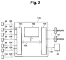
- Figure 2 the electrohydraulic Brake system controlling control unit shown is.
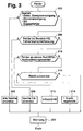
- Figure 3 shows a flow diagram which is a preferred one Realization of the emergency operations of an electro-hydraulic Brake system as a program of a microcomputer represents.
- Figure 1 shows a preferred embodiment of a electrohydraulic brake system. It shows a master brake cylinder HBZ with storage container 10 to which one from Driver operated brake pedal is attached. Further is a hydraulic unit 14 is provided, which valve and Pump arrangements for controlling the wheel brakes 16, 18, 20 and contains 22. With the brake pedal 12 is a brake pedal switch 24 connected, which when the brake pedal is pressed closes, and a measuring device 26 for detecting the deflection of the brake pedal.
- the brake pedal switch can be used as simple closer can be designed, or for improvement the ability to be monitored as a double switch with an NC contact and a closer. Likewise, the measuring device 26 for Detection of the deflection of the pedal can be designed redundantly.
- a pedal travel simulator PWS is also provided, which a counterforce for the driver when the brake pedal is pressed simulated.
- On the master brake cylinder HBZ are the two brake circuits HZ1 and HZ2 connected. In these are one isolating valve each MV_TVR and MV_TVL inserted, which closed by energization in the case of an electrically controlled brake system becomes.
- a pressure sensor 28 from the driver via the Brake pedal actuation applied pressure.
- the main brake cylinder is hydraulically separated from the isolating valves Pressure control system disconnected. In the pressure control system are for each wheel brake has a pressure modulator for brake pressure control contain.
- a pressure modulator consists of one Inlet valve (MV_UVR, MV_UVL, MV_UHR, MV_UHL), one outlet valve each (MV_DVR, MV_DVL, MV_DHR, MV_DHL) and one each Pressure sensor 30, 32, 34 and 36, which the pressure in the wheel brake leading management measures.
- MV_UVR, MV_UVL, MV_UHR, MV_UHL Inlet valve
- MV_DVR MV_DVL
- MV_DHR MV_DHR
- MV_DHL Pressure sensor 30, 32, 34 and 36
- relief valves are MV_EVA and MV_EHA for everyone Axis provided, the pressure reduction in the de-energized state allow from the wheel pressure modulators of an axle. You connect the pressure modulators of an axis with those to the reservoir 10 leading return lines. In the electrically controlled Operating status, these two valves are permanent energized, i.e. closed. There is also a temperature compensation valve MV_TKVL and MV_TKVR for everyone Front wheel pressure modulator provided. These valves are deenergized are closed and are released from the pressure modulator for pressure reduction of a front wheel opened by energization when certain conditions, especially a very long one Braking time. The temperature compensation valves connect the brake line to the wheel brake with the return line.
- the energy for brake pressure modulation comes from a single-piston high-pressure pump driven by an electric motor 42. This is at a high pressure accumulator 44 connected, which serves as an intermediate buffer and its pressure is detected by a pressure sensor 46.
- the pressure line of the Pump 42 leads to the inlet valves of the wheel brakes while the suction line of the pump 42 connected to the reservoir 10 is.
- the relief valves MV_EVx and the temperature compensation valves MV_TKx are omitted in one Embodiment.
- the brake system described in FIG. 1 operates in normal operation as follows.
- the driver steps on the brake pedal. He senses a path-dependent counterforce. This path dependency is defined by the characteristic of the pedal travel simulator educated.
- the brake pedal switch and / or the The isolating valves (MV_TVR and MV_TVL) and the relief valves (MV_EVA and MV_EHA) closed.
- the Master brake cylinder HBZ builds up a pressure that from the Pedal force results. From the signals of the brake light switch 24, the displacement sensor 26 and / or the pressure sensor 28 the driver's braking request, for example, as a target deceleration or calculated as the target braking force.
- the individual target wheel brake pressures are formed. Each these pressures depend on the driving condition and slip condition modified and via the wheel pressure modulators through valve energization adjusted. Be in a closed loop the current pressures on the wheel pressure sensors for each wheel brake used for the target-actual comparison. With different Target pressures in the left and right wheel one The equalization valves are closed in each axis Wheel brake the predetermined target pressure by controlling the intake and exhaust valves in the sense of regulating the actual brake pressure adjusted to the target brake pressure. To build up pressure on a wheel brake, the inlet valve is energized so far, that the desired target pressure in the wheel brake with the desired dynamics. A decrease in pressure is achieved accordingly by energizing the exhaust valve, taking brake fluid over to the reservoir the return line flows back.
- the relief valves come into effect in the event of a fault in the system. If during if the braking system fails, all fall Valves return to their de-energized state. The relief valves then open the pressure modulators to the return line, so that no brake pressure can be locked up. These valves also allow volume compensation in the idle state to the container in case of temperature fluctuations.
- the electrically operated valves and the pump 42 are controlled by at least one electronic control unit, which is outlined in Figure 2. It includes at least a microcomputer 102, an input circuit 104, an output circuit 106 and a connecting these elements Bus system 108 for mutual data exchange.
- Input circuit 104 is lines 50 and 54 of FIG Brake pedal switch 24 and pedal travel sensor 26 supplied. Further input lines 118 through 124 connect the input circuit 104 with the sensors assigned to each wheel brake 30 to 36.
- An input line 140 is also provided, that of the measuring device 46 for detecting the storage pressure is fed to the input line 104.
- Other input lines 126 to 128 connect the input circuit 104 with measuring devices 130 to 132 for detecting further Operating parameters of the brake system, the vehicle and / or its Drive unit.
- Such operating sizes are, for example the wheel speeds, possibly that of the engine torque, axle loads, the Pressure in the brake line (sensor 28), etc.
- To the output circuit 106 several output lines are connected. The output lines are shown by way of example which the valves of the pressure modulators are operated.
- the pump 42 is controlled via a further output line 138.
- the control unit 100 controls the brake system depending on of the supplied signal quantities in the above Senses.
- FIG 3 is a preferred embodiment for emergency braking operations and their selection with an electrohydraulic Brake system shown.
- the program outlined runs for at least one detected error as long as error monitoring is active, i.e. if the electrical Brake control is not completely switched off.
- the error monitoring itself i.e. the determination of the type of error, takes place in others not specifically listed here Programs instead.
- a failure of the electrical power supply, hydraulic pressure supply, an internal control unit error or a double error i.e. at least one error at different Axes.
- the failure of the electrical power supply e.g. by monitoring the battery voltage and / or the generator current is detected, the failure of the pressure supply e.g. by monitoring for limit values of the storage pressure and / or the storage pressure gradient.
- Internal Control unit faults are monitored by normal monitoring the components, e.g. by means of a watchdog, electronic Memory test, potential checks, etc. determined.
- Step 202 de-energized all valves.
- the electrical Control can no longer be maintained under any circumstances become.
- the Pressure build-up by the driver through muscle power without braking power support via the master brake cylinder on the front axle upset.
- the rear axle remains unbraked.
- a warning to the driver e.g. via a warning lamp that informs the driver of the error and / or informs emergency braking and the program ends.
- emergency braking remains at least until the next start of an operating cycle received, the program will no longer run.
- step 206 If none of the errors described in step 200 are present, it is checked in step 206 whether an error in the area of Driver request recording, e.g. a sensor failure, a There is an error in the pedal travel simulator, etc.
- an error in the area of Driver request recording e.g. a sensor failure, a There is an error in the pedal travel simulator, etc.
- step 208 Emergency braking operation initiated, which leads to a de-energization of the valves on the front axle.
- the Pressure build-up on the front axle as applied by the driver above become.
- the rear axle will continue to be in electrically controlled operation keep with the error-free sensor signal for formation the braking request is used.
- the wheel pressure sensors in this case the front axle brake is used for monitoring the electrical control system by sending their signals with the driver's request be compared. In the event of impermissible deviations there is a double fault, which then leads to emergency braking after step 202.
- step 210 If there is no error in the area of determining the driver’s request, it is checked in step 210 whether a fault in a component of the hydraulic unit. To find out extensive error checks are planned. So e.g. the deviation for each wheel outside of braking between measured brake pressure and target pressure with a permissible deviation compared. Also becomes an impermissible Memory pressure change found can be erroneous Component a strongly leaky or open inlet valve be isolated. Is not an impermissible change in the memory pressure to recognize a non-opening isolation valve, a non-opening temperature compensation valve or clogged line, in the case of rear axle brakes through a non-opening relief or balance valve or one blocked line detected.
- step 212 Emergency braking operation a so-called 3-wheel EMS operation was initiated, by closing the front axle balance valve is so that on the wheel of the front axle on which the defect occurred, no more pressure is built up. Because a bike individual Regulation on this bike is no longer possible are wheel-specific functions (e.g. driving dynamics control) switched off, the anti-lock function can, however, for the remaining three wheels remain active.
- the normally closed Removal valve of the insulated wheel is in regular time intervals briefly controlled to a solved To ensure brake. To build a strong yaw moment Avoid a yaw moment limitation, its basic Functionality is known from the prior art, advantageous.
- Step 214 checks whether a wheel pressure sensor is clearly defective is. This can be done based on a hardware check (e.g. measuring the internal resistance, etc.).
- the emergency braking operation according to step 216 a control of an axis in the context of a pressure control loop initiated.
- the balance valve of the axle of the wheel, on which the error occurred opened, and in both wheel brakes this axis the pressure according to the Setpoint and the actual value of the wheel regulated, which the correct working wheel pressure sensor is assigned.
- Individual bike Functions must also be switched off here, if necessary the ABS function for the other, from emergency braking Axis not affected can still be active.
- step 214 If the error checked in step 214 is also not present, becomes the driver as in steps 202, 208, 212, 216 warned, but without restriction or only comfort restrictions such as. a harder or softer pedal. This is e.g. then the case if due to the change of the Storage pressure when pressure builds up in the wheels air in one or more wheel tongs was found.
- it is used as an emergency braking operation braking via muscle power operation on a wheel and electric Regulation made on the remaining three wheels. This is especially true when a media separator is not moving leaves.
- the wheel that this media burner is assigned to is operated by the driver via the master cylinder, the rest three wheels are still in electrohydraulic Operation regulated.
- the described emergency braking operations are also in connection with error detection measures that differ from the differentiate above.
- valve arrangements controlling the wheel brake pressures be de-energized that in the event of an error in the brake request recording only those assigned to the front axle Valve assemblies can be switched currentless that at an error affecting the ability to build or depressurize affects only one wheel (e.g. failure of a valve arrangement), an electrical control on only three wheel brakes is made and that in the event of an error that is only a Wheel affects an axle without the ability to pressurize and - affect the dismantling of this bike (e.g. a Pressure sensor error), a common control of an axis in the Framework of a pressure control loop takes place.
Landscapes
- Engineering & Computer Science (AREA)
- Transportation (AREA)
- Mechanical Engineering (AREA)
- Physics & Mathematics (AREA)
- Fluid Mechanics (AREA)
- Regulating Braking Force (AREA)
- Valves And Accessory Devices For Braking Systems (AREA)
- Braking Systems And Boosters (AREA)
Abstract
Description
Die Erfindung betrifft ein Verfahren und eine Vorrichtung zur Steuerung einer Bremsanlage gemäß den Oberbegriffen der unabhängigen Patentansprüche.The invention relates to a method and a device to control a brake system according to the generic terms of independent claims.
Ein derartiges Verfahren bzw. eine derartige Vorrichtung ist beispielsweise aus dem SAE-Paper 960991 bekannt. Dort wird eine elektrohydraulische Bremsanlage beschrieben, bei welcher aus der Bremspedalbetätigung durch den Fahrer ein Bremswunsch des Fahrers abgeleitet wird. Dieser Bremswunsch wird gegebenenfalls unter Berücksichtigung von weiteren Betriebsgrößen in Sollbremsdrücke für die einzelnen Radbremsen umgerechnet. Die Sollbremsdrücke werden für jedes Rad durch Druckregelkreise auf der Basis des vorgegebenen Solldrucks sowie des im Bereich der Radbremse gemessenen Istbremsdrucks eingeregelt. Da der Bremsdruck in den Radbremsen bei einer derartigen elektrohydraulischen Bremsanlage abhängig vom Fahrerbremswunsch auf elektrischem Wege über Ventilanordnungen eingestellt und moduliert wird, sind im Fehlerfall Notbremsbetriebe sicherzustellen, die eine ausreichende Bremswirkung auch im Fehlerfall gewährleisten. Bei der bekannten Bremsanlage wird in diesem Zusammenhang ein Abschalten des elektrischen Systems und ein Umschalten auf eine hydraulische Bremse oder der elektrische Betrieb nur dreier Radbremsen vorgeschlagen. Damit können die meisten Fehler zufriedenstellend beherrscht werden, allerdings wird dennoch in einigen Fällen auf den hydraulischen Betrieb umgeschaltet.Such a method or device is known for example from SAE paper 960991. There will described an electro-hydraulic brake system in which from the brake pedal actuation by the driver The driver's braking request is derived. This braking request If necessary, taking into account other company sizes in target brake pressures for the individual wheel brakes converted. The target braking pressures are set for each wheel Pressure control loops based on the specified target pressure and the actual brake pressure measured in the area of the wheel brake adjusted. Since the brake pressure in the wheel brakes at one such electro-hydraulic brake system depending on Driver braking request electronically via valve arrangements in the event of a fault, emergency braking operations are set and modulated ensure the adequate braking effect guarantee even in the event of a fault. With the known In this context, the braking system is switched off electrical system and a switch to a hydraulic one Brake or electrical operation of only three wheel brakes suggested. With this, most mistakes can be satisfactory be mastered, however, is still in switched to hydraulic operation in some cases.
Es ist Aufgabe der Erfindung, Notbremsbetriebe einer elektrisch gesteuerten Bremsanlage anzugeben, durch die so wenig wie möglich im Fehlerfall auf eine direkte mechanische Einwirkung des Fahrers auf die Radbremsen umgeschaltet werden muß.It is an object of the invention to provide emergency braking operations electrically Controlled braking system to specify by so little as possible in the event of a fault on direct mechanical action of the driver can be switched to the wheel brakes got to.
Dies wird durch die kennzeichnenden Merkmale der unabhängigen Patentansprüche erreicht.This is due to the distinctive features of the independent Claims reached.
Es wird ein Notbetriebssystem einer elektrisch gesteuerten Bremsanlage vorgestellt, bei welchem je nach Fehlerfall unterschiedliche Notbremsbetriebe eingeleitet werden. In vorteilhafter Weise wird ein vollständiges Abschalten der elektrischen Steuerung nur noch in wenigen, schwerwiegenden Fehlern erforderlich.It becomes an electrically operated emergency operating system Brake system presented, in which depending on the fault different Emergency braking operations are initiated. In advantageous Way, a complete shutdown of the electrical Control only in a few serious errors required.
Dadurch wird die Verfügbarkeit der elektrischen Steuerung verbessert, ohne daß die Betriebssicherheit gefährdet ist.This will increase the availability of the electrical control improved without jeopardizing operational safety.
Besonders vorteilhaft ist, daß auch im Fehlerfall eine gegenüber dem vollständigen Abschalten verbesserte Bremswirkung erreicht wird, insbesondere eine Bremskraftverstärkung stattfindet.It is particularly advantageous that, even in the event of a fault, one opposite improved braking effect when completely switched off is achieved, in particular a brake booster takes place.
Als Notbremsbetriebe stehen neben dem eingangs genannten 3-Rad-EHB-Betrieb eine Regelung, bei der die Radbremsen einer Achse gemeinsam geregelt werden und ein Abschalten der elektrischen Steuerung an einer Achse, während an einer anderen weiterhin elektrisch gesteuert wird. Damit wird die Anzahl der Notbremsbetriebe erhöht und das Bremsverhalten im Fehlerfall erheblich verbessert.In addition to the 3-wheel EMS operation mentioned at the beginning, there are emergency braking operations a scheme in which the wheel brakes a Axis can be regulated together and a shutdown of the electrical Control on one axis while on another continues to be electrically controlled. So the number of emergency braking operations and braking behavior in the event of a fault significantly improved.
Weitere Vorteile ergeben sich aus der nachfolgenden Beschreibung von Ausführungsbeispielen bzw. aus den abhängigen Patentansprüchen.Further advantages result from the description below from exemplary embodiments or from the dependent ones Claims.
Die Erfindung wird nachstehend anhand der in der Zeichnung dargestellten Ausführungsformen näher erläutert. Dabei zeigt Figur 1 ein bevorzugtes Ausführungsbeispiel einer elektrohydraulischen Bremsanlage, während in Figur 2 die die elektrohydraulische Bremsanlage steuernde Steuereinheit dargestellt ist. Figur 3 zeigt ein Flußdiagramm, das eine bevorzugte Realisierung der Notbetriebe einer elektrohydraulischen Bremsanlage als Programm eines Mikrocomputers darstellt.The invention is described below with reference to the drawing illustrated embodiments explained in more detail. It shows Figure 1 shows a preferred embodiment of an electrohydraulic Brake system, while in Figure 2 the electrohydraulic Brake system controlling control unit shown is. Figure 3 shows a flow diagram which is a preferred one Realization of the emergency operations of an electro-hydraulic Brake system as a program of a microcomputer represents.
Figur 1 zeigt ein bevorzugtes Ausführungsbeispiel einer
elektrohydraulischen Bremsanlage. Sie zeigt einen Hauptbremszylinder
HBZ mit Vorratsbehälter 10, an den ein vom
Fahrer betätigbares Bremspedal angebracht ist. Ferner ist
ein Hydraulikaggregat 14 vorgesehen, welches Ventil- und
Pumpenanordnungen zur Steuerung der Radbremsen 16, 18, 20
und 22 enthält. Mit dem Bremspedal 12 ist ein Bremspedalschalter
24 verbunden, welcher bei Betätigen des Bremspedals
schließt, und eine Meßeinrichtung 26 zur Erfassung der Auslenkung
des Bremspedals. Der Bremspedalschalter kann als
einfacher Schließer ausgelegt sein, oder zur Verbesserung
der Überwachbarkeit als doppelter Schalter mit einem Öffner
und einem Schließer. Ebenso kann die Meßeinrichtung 26 zur
Erfassung der Auslenkung des Pedals redundant ausgelegt werden.
Ferner ist ein Pedalwegsimulator PWS vorgesehen, welcher
für den Fahrer bei Betätigen des Bremspedals eine Gegenkraft
simuliert. An den Hauptbremszylinder HBZ sind die
zwei Bremskreise HZ1 und HZ2 angeschlossen. In diesen sind
jeweils ein Trennventil MV_TVR und MV_TVL eingefügt, welches
bei elektrisch gesteuerter Bremsanlage durch Bestromung geschlossen
wird. Vor dem Trennventil mißt in zumindest einem
der Bremskreise ein Drucksensor 28 den vom Fahrer über die
Bremspedalbetätigung aufgebrachten Druck. Bei geschlossenen
Trennventilen ist der Hauptbremszylinder hydraulisch vom
Druckregelsystem abgetrennt. Im Druckregelsystem sind für
jede Radbremse ein Druckmodulator für die Bremsdruckregelung
enthalten. Ein Druckmodulator besteht dabei aus je einem
Einlaßventil (MV_UVR, MV_UVL, MV_UHR, MV_UHL), je einem Auslaßventil
(MV_DVR, MV_DVL, MV_DHR, MV_DHL) und je einem
Drucksensor 30, 32, 34 und 36, der den Druck in der zur Radbremse
führenden Leitung mißt. In den beiden Vorderraddruckmodulatoren
befindet sich je ein Medientrennerkolben 38 und
40 zwischen den Ventilen (Ein- und Auslaßventil) und den
Drucksensoren bzw. der Radbremse. Die Druckmodulatoren sind
über Ausgleichsventile MV_BVA und MV_BHA verbunden, die bei
Bestromung voneinander unabhängig gesteuert werden können.
Ferner sind Entlastungsventile MV_EVA bzw. MV_EHA für jede
Achse vorgesehen, die in unbestromtem Zustand den Druckabbau
aus den Raddruckmodulatoren einer Achse erlauben. Sie verbinden
die Druckmodulatoren einer Achse mit den zum Vorratsbehälter
10 führenden Rückfuhrleitungen. Im elektrisch gesteuerten
Betriebszustand sind diese beiden Ventile permanent
bestromt, d.h. geschlossen. Ferner ist jeweils ein Temperaturkompensationsventil
MV_TKVL und MV_TKVR für jeden
Vorderraddruckmodulator vorgesehen. Diese Ventile sind unbestromt
geschlossen und werden zum Druckabbau aus dem Druckmodulator
eines Vorderrades durch Bestromung geöffnet, wenn
bestimmte Bedingungen, insbesondere eine sehr lange
Bremsdauer, vorliegen. Die Temperaturkompensationsventile
verbinden die Bremsleitung zur Radbremse mit der Rücklaufleitung.
Die Energie für die Bremsdruckmodulation kommt aus
einer von einem Elektromotor angetriebenen Einkolben-Hochdruckpumpe
42. Diese ist an einen Hochdruckspeicher 44
angeschlossen, der als Zwischenpuffer dient und dessen Druck
durch einen Drucksensor 46 erfaßt wird. Die Druckleitung der
Pumpe 42 führt zu den Einlaßventilen der Radbremsen, während
die Saugleitung der Pumpe 42 mit dem Vorratsbehälter 10 verbunden
ist. Bezüglich Einzelheiten der hydraulischen Schaltung
wird auf das in Figur 1 dargestellte bevorzugte Ausführungsbeispiel
verwiesen. Die Entlastungsventile MV_EVx und
die Temperaturkompensationsventile MV_TKx entfallen in einem
Ausführungsbeispiel.Figure 1 shows a preferred embodiment of a
electrohydraulic brake system. It shows a master brake cylinder
HBZ with
Die nachfolgend beschriebene erfindungsgemäße Vorgehensweise wird jedoch nicht nur in Verbindung mit einer solchen Hydraulikschaltung vorteilhaft angewendet, sondern überall dort, wo Notbremsbetriebe im Fehlerfall einer elektrisch gesteuerten Bremsanlage eingerichtet werden müssen.The procedure according to the invention described below is not only in connection with such a hydraulic circuit applied advantageously, but everywhere where emergency braking operations in the event of an electrically controlled failure Brake system must be set up.
Im Normalbetrieb arbeitet die in Figur 1 beschriebene Bremsanlage
wie folgt. Der Fahrer tritt auf das Bremspedal. Er
spürt dabei eine wegabhängige Gegenkraft. Diese Wegabhängigkeit
wird durch die definierte Charakteristik des Pedalwegsimulators
gebildet. Bei Sensierung eines Bremswunsches
über den Pedalwegsensor, den Bremspedalschalter und/oder den
Drucksensor werden die Trennventile (MV_TVR und MV_TVL) und
die Entlastungsventile (MV_EVA und MV_EHA) geschlossen. Im
Hauptbremszylinder HBZ baut sich ein Druck auf, der aus der
Pedalkraft resultiert. Aus den Signalen des Bremslichtschalters
24, des Wegsensors 26 und/oder des Drucksensors 28 wird
der Bremswunsch des Fahrers beispielsweise als Sollverzögerung
oder als Sollbremskraft errechnet. Aus diesem Bremswunsch
werden die einzelnen Sollradbremsdrücke gebildet. Je
nach Fahrzustand und Schlupfbedingung werden diese Drücke
modifiziert und über die Raddruckmodulatoren durch Ventilbestromungen
eingeregelt. Im geschlossenen Regelkreis werden
bei jeder Radbremse die aktuellen Drücke an den Raddrucksensoren
für den Soll-Ist-Abgleich herangezogen. Bei unterschiedlichen
Solldrücken im linken und rechten Rad einer
Achse werden die Ausgleichsventile geschlossen und in jeder
Radbremse der vorgegebene Solldruck durch Ansteuern der Einlaß- und Auslaßventile im Sinne einer Regelung des Ist-Bremsdruckes
auf den Sollbremsdruck eingeregelt. Zum Druckaufbau
an einer Radbremse wird das Einlaßventil so weit bestromt,
daß sich der gewünschte Solldruck in der Radbremse
mit der gewünschten Dynamik ausbildet. Eine Druckabnahme
wird entsprechend durch Bestromung des Auslaßventils erreicht,
wobei Bremsflüssigkeit in den Vorratsbehälter über
die Rücklaufleitung zurückfließt. Die Entlastungsventile
kommen im Fehlerfall des Systems zur Wirkung. Wenn während
einer Bremsung das elektrische System ausfällt, fallen alle
Ventile in ihren unbestromten Zustand zurück. Die Entlastungsventile
öffnen dann die Druckmodulatoren zur Rücklaufleitung,
so daß kein Bremsdruck eingesperrt werden kann.
Ebenso gestatten diese Ventile im Ruhezustand den Volumenausgleich
zum Behälter bei Temperaturschwankungen.The brake system described in FIG. 1 operates in normal operation
as follows. The driver steps on the brake pedal. He
senses a path-dependent counterforce. This path dependency
is defined by the characteristic of the pedal travel simulator
educated. When sensing a braking request
via the pedal travel sensor, the brake pedal switch and / or the
The isolating valves (MV_TVR and MV_TVL) and
the relief valves (MV_EVA and MV_EHA) closed. in the
Master brake cylinder HBZ builds up a pressure that from the
Pedal force results. From the signals of the
Eine Betätigung der Pumpe 42 findet bei aktivem Bremsvorgang
und/oder bei einem Absinken des Speicherdrucks im Speicher
44 unter einen vorbestimmten Wert statt. Neben dieser Funktion
wird der erfaßte Speicherdruck 46 auch im Rahmen der
Regelung ausgewertet, da er im wesentlichen den am Eingang
der Einlaßventile liegenden Druck repräsentiert.
Die elektrisch betätigbaren Ventile sowie die Pumpe 42 werden
von wenigstens einer elektronischen Steuereinheit angesteuert,
die in Figur 2 skizziert ist. Sie umfaßt dabei wenigstens
einen Mikrocomputer 102, eine Eingangsschaltung
104, eine Ausgangsschaltung 106 und ein diese Elemente verbindendes
Bussystem 108 zum gegenseitigen Datenaustausch.
Der Eingangsschaltung 104 sind die Leitungen 50 und 54 von
Bremspedalschalter 24 und Pedalwegsensor 26 zugeführt. Ferner
verbinden Eingangsleitungen 118 bis 124 die Eingangsschaltung
104 mit den jeder Radbremse zugeordneten Sensoren
30 bis 36. Ferner ist eine Eingangsleitung 140 vorgesehen,
die von der Meßeinrichtung 46 zur Erfassung des Speicherdrucks
der Eingangsleitung 104 zugeführt ist. Weitere Eingangsleitungen
126 bis 128 verbinden die Eingangsschaltung
104 mit Meßeinrichtungen 130 bis 132 zur Erfassung weiterer
Betriebsgrößen der Bremsanlage, des Fahrzeugs und/oder dessen
Antriebseinheit. Derartige Betriebsgrößen sind beispielsweise
die Radgeschwindigkeiten, gegebenenfalls das von
der Antriebseinheit abgegebene Motormoment, Achslasten, der
Druck in der Bremsleitung (Sensor 28), etc. An die Ausgangsschaltung
106 sind mehrere Ausgangsleitungen angeschlossen.
Beispielhaft sind die Ausgangsleitungen dargestellt, über
welche die Ventile der Druckmodulatoren betätigt werden.
Über eine weitere Ausgangsleitung 138 wird die Pumpe 42 angesteuert.
Die Steuereinheit 100 steuert die Bremsanlage abhängig
von den zugeführten Signalgrößen im oben dargestellten
Sinne.The electrically operated valves and the
In Figur 3 ist ein bevorzugtes Ausführungsbeispiel für Notbremsbetriebe und deren Auswahl bei einer elektrohydraulischen Bremsanlage dargestellt. Das skizzierte Programm läuft bei wenigstens einem erkannten Fehler ab, solange die Fehlerüberwachung aktiv ist, d.h. wenn die elektrische Bremsensteuerung nicht vollständig abgeschaltet ist. Die Fehlerüberwachung selbst, d.h. die Ermittlung der Fehlerart, findet in anderen, hier nicht speziell aufgeführten Programmen statt. In Figure 3 is a preferred embodiment for emergency braking operations and their selection with an electrohydraulic Brake system shown. The program outlined runs for at least one detected error as long as error monitoring is active, i.e. if the electrical Brake control is not completely switched off. The error monitoring itself, i.e. the determination of the type of error, takes place in others not specifically listed here Programs instead.
Nach Start des Programms bei wenigstens einem erkannten Fehler
wird im ersten Schritt 200 überprüft, ob ein Ausfall der
elektrischen Energieversorgung, der hydraulischen Druckversorgung,
ein interner Fehler der Steuereinheit oder ein Doppelfehler,
d.h. zumindest je ein Fehler an verschiedenen
Achsen vorliegt. Der Ausfall der elektrischen Energieversorgung
wird z.B. durch Überwachung der Batteriespannung
und/oder des Generatorstroms erkannt, der Ausfall der Druckversorgung
z.B. durch Überwachung auf Grenzwerte des Speicherdrucks
und/oder des Speicherdruckgradienten. Interne
Fehler des Steuergerät werden durch übliche Überwachungen
der Komponenten, wie z.B. mittels eines Watchdogs, elektronische
Speichertest, Potentialüberprüfungen, etc. festgestellt.After starting the program with at least one detected error
it is checked in a
Ist einer dieser Fehler festgestellt worden, werden gemäß
Schritt 202 alle Ventile stromlos geschaltet. Die elektrische
Steuerung kann unter keinen Umständen mehr aufrechtgehalten
werden. Im Rahmen dieses Notbremsbetriebs wird der
Druckaufbau vom Fahrer durch Muskelkraft ohne Bremskraftunterstützung
über den Hauptbremszylinder an der Vorderachse
aufgebracht. Die Hinterachse bliebt ungebremst. Danach wird
an den Fahrer eine Warnung ausgegeben (Schritt 204), z.B.
über eine Warnlampe, die den Fahrer über den Fehler und/oder
den Notbremsbetrieb informiert und das Programm beendet. Da
die elektrische Steuerung abgeschaltet ist, bleibt der Notbremsbetrieb
zumindest bis zum nächsten Start eines Betriebszyklus
erhalten, das Programm wird nicht mehr durchlaufen.If one of these errors has been found, according to
Liegt keiner der in Schritt 200 beschriebenen Fehler vor,
wird im Schritt 206 überprüft, ob ein Fehler im Bereich der
Fahrerwunscherfassung, z.B. ein Ausfall eines Sensors, ein
Fehler des Pedalwegsimulators, etc. vorliegt. Diese Fehler,
vor allem Sensorausfälle werden z.B. durch Vergleich der
Sensorsignalen miteinander und gegebenenfalls mit einem weiteren
Sensorsignal festgestellt, oder durch Überprüfen des
Signals des jeweiligen Sensors allein auf Grenzwerte.If none of the errors described in
Wird ein solcher Fehler erkannt, wird nach Schritt 208 ein
Notbremsbetrieb eingeleitet, welcher zu einem Stromlosschalten
der Ventile der Vorderachse führt. Dadurch muß der
Druckaufbau an der Vorderachse wie oben vom Fahrer aufgebracht
werden. Kann der fehlerhafte Sensor ermittelt werden,
wird die Hinterachse weiterhin im elektrisch gesteuerten Betrieb
behalten, wobei das fehlerfreie Sensorsignal zur Bildung
des Bremswunsch herangezogen wird. Die Raddrucksensoren
der Vorderachsbremse dienen in diesem Fall zur Überwachung
der elektrischen Steuerung, indem deren Signale mit dem Fahrerwunsch
verglichen werden. Bei unzulässigen Abweichungen
liegt ein Doppelfehler vor, der dann zu einem Notbremsbetrieb
nach Schritt 202 führt.If such an error is detected, a step is made after
Liegt kein Fehler im Bereich der Fahrerwunschermittlung vor,
wird im Schritt 210 überprüft, ob ein Fehler an einer Komponente
des Hydraulikaggregats vorliegt. Zu dessen Feststellung
sind umfangreiche Fehlerüberprüfungen vorgesehen. So
wird z.B. außerhalb einer Bremsung für jedes Rad die Abweichung
zwischen gemessenem Bremsdruck und Solldruck mit einer
zulässigen Abweichung verglichen. Wird ferner eine unzulässige
Speicherdruckänderung festgestellt, kann als fehlerhafte
Komponente ein stark undichtes bzw. offenes Einlaßventil
isoliert werden. Ist keine unzulässige Änderung des Speicherdrucks
zu erkennen, wird ein nichtöffnendes Trennventil,
ein nichtöffnendes Temperaturkompensationsventil oder eine
verstopfte Leitung, im Falle der Hinterachsbremsen durch ein
nichtöffnendes Entlastungs- oder Balanceventil bzw. eine
verstopften Leitung erkannt. Bei Vorliegen einer Druckaufbauphase
wird bei einer unzulässigen Abweichung des Istdrucks
vom Solldruck und gleichzeitiger zu großer Aufbauzeit
und unzulässigem Speicherdruckabfall ein undichtes Auslaßventil
oder eine Leckage im Bereich der Bremsanlage zwischen
dem Speicher und dem Medienbrenner erkannt. Liegt wenigstens
eine der beiden letzten Bedingungen nicht vor, wird z.B. von
einem nichtöffnenden Einlaßventil ausgegangen. Bei einem
Druckabbau wird die Ansteuerzeit T auf Überschreiten einer
maximalen Druckabbauansteuerzeit und der Speicherdruckgradient
überprüft. Überschreitet die Abbauzeit die Maximalzeit
und ist der Speicherdruckgradient unzulässig groß, wird ein
nicht schließendes Einlaßventil angenommen. Ist eine der Bedingungen
nicht erfüllt und weichen Radbremsistdruck und
Radbremssolldruck unzulässig voneinander ab, kommt als Ursache
ein nichtöffnendes Auslaßventil, ein hängender Medientrenner
und/oder ein nichtöffnendes Temperaturkompensationsventil
in Betracht.If there is no error in the area of determining the driver’s request,
it is checked in
Liegt einer dieser Fehler vor, wird gemäß Schritt 212 als
Notbremsbetrieb ein sogenannter 3-Rad-EHB-Betrieb eingeleitet,
indem das Balanceventil der Vorderachse geschlossen
wird, so daß an dem Rad der Vorderachse, an dem der Defekt
aufgetreten ist, kein Druck mehr aufgebaut wird. Da eine radindividuelle
Regelung an diesem Rad nicht mehr möglich ist,
sind radindividuelle Funktionen (z.B. Fahrdynamikregelung)
abgeschaltet, die Antiblockierschutzfunktion kann jedoch für
die restlichen drei Räder aktiv bleiben. Das stromlos geschlossene
Abbauventil des isolierten Rades wird in regelmäßigen
zeitlichen Abständen kurz angesteuert, um eine gelöste
Bremse zu gewährleisten. Um einen starken Giermomentenaufbau
zu vermeiden, ist eine Giermomentenbegrenzung, deren prinzipielle
Funktionsweise aus dem Stand der Technik bekannt ist,
vorteilhaft.If one of these errors is present, then in accordance with
Wurde keiner der Fehler gemäß Schritt 210 ermittelt, wird im
Schritt 214 überprüft, ob ein Raddrucksensor eindeutig defekt
ist. Dies kann auf der Basis einer Hardwareüberprüfung
erfolgen (z.B. Messen des Innenwiderstands, etc.).If none of the errors were determined in accordance with
In diesem Fall wird als Notbremsbetrieb gemäß Schritt 216 eine Regelung einer Achse im Rahmen eines Druckregelkreises eingeleitet. Dazu wird das Balanceventil der Achse des Rades, an dem der Fehler aufgetreten ist, geöffnet, und in beiden Radbremsen dieser Achse der Druck nach Maßgabe des Sollwerts und des Istwertes des Rades geregelt, dem der korrekt arbeitende Raddrucksensor zugeordnet ist. Radindividuelle Funktionen sind auch hier abzuschalten, wobei gegebenenfalls die ABS-Funktion für die andere, vom Notbremsbetrieb nicht betroffene Achse weiter aktiv sein kann.In this case, the emergency braking operation according to step 216 a control of an axis in the context of a pressure control loop initiated. To do this, the balance valve of the axle of the wheel, on which the error occurred, opened, and in both wheel brakes this axis the pressure according to the Setpoint and the actual value of the wheel regulated, which the correct working wheel pressure sensor is assigned. Individual bike Functions must also be switched off here, if necessary the ABS function for the other, from emergency braking Axis not affected can still be active.
Liegt auch der in Schritt 214 überprüfte Fehler nicht vor,
wird wie nach den Schritten 202, 208, 212, 216, der Fahrer
gewarnt, allerdings ohne Einschränkung oder nur Komforteinschränkungen
wie z.B. ein härteres oder weicheres Pedal.
Dies ist z.B. dann der Fall, wenn aufgrund der Änderung des
Speicherdrucks beim Druckaufbau in den Rädern Luft in einer
oder mehreren Radzangen festgestellt wurde.If the error checked in
In einer vorteilhaften Ausführung wird als Notbremsbetrieb eine Bremsung über Muskelkraftbetrieb an einem Rad und elektrischer Regelung an den restlichen drei Rädern vorgenommen. Dies vor allem dann, wenn sich ein Medientrenner nicht bewegen läßt. Das Rad, dem dieser Medienbrenner zugeordnet ist, wird vom Fahrer über den Hauptzylinder bedient, die restlichen drei Räder werden nach wie vor im elektrohydraulischen Betrieb geregelt.In an advantageous embodiment, it is used as an emergency braking operation braking via muscle power operation on a wheel and electric Regulation made on the remaining three wheels. This is especially true when a media separator is not moving leaves. The wheel that this media burner is assigned to is operated by the driver via the master cylinder, the rest three wheels are still in electrohydraulic Operation regulated.
Die geschilderten Notbremsbetriebe werden auch in Verbindung mit Fehlererkennungsmaßnahmen angewendet, die sich von den vorstehend dargestellten unterscheiden. The described emergency braking operations are also in connection with error detection measures that differ from the differentiate above.
Wesentlich ist, daß bei einem schwerwiegenden Fehler wie ein Ausfall der elektrischen Energieversorgung, der Druckversorgung oder ein elektrischer Fehler der die Bremsen steuernden Steuereinheit die die Radbremsdrücke steuernde Ventilanordnungen stromlos geschaltet werden, daß bei einem Fehler in der Bremswunscherfassung nur die der Vorderachse zugeordneten Ventilanordnungen stromlos geschaltet werden, daß bei einem Fehler, der die Fähigkeit zum Druckaufbau oder Druckabbau an nur einem Rad betrifft (z.B. Fehler einer Ventilanordnung), eine elektrische Steuerung an nur drei Radbremsen vorgenommen wird und daß bei einem Fehler, der nur ein Rad einer Achse betrifft, ohne die Fähigkeit des Druckauf- und -abbaus an diesem Rad zu beeinträchtigen (z.B. ein Drucksensorfehler), eine gemeinsame Regelung einer Achse im Rahmen eines Druckregelkreises stattfindet.It is essential that in the event of a serious error such as a Failure of the electrical power supply, the pressure supply or an electrical failure of the brakes controlling Control unit the valve arrangements controlling the wheel brake pressures be de-energized that in the event of an error in the brake request recording only those assigned to the front axle Valve assemblies can be switched currentless that at an error affecting the ability to build or depressurize affects only one wheel (e.g. failure of a valve arrangement), an electrical control on only three wheel brakes is made and that in the event of an error that is only a Wheel affects an axle without the ability to pressurize and - affect the dismantling of this bike (e.g. a Pressure sensor error), a common control of an axis in the Framework of a pressure control loop takes place.
Claims (9)
Applications Claiming Priority (2)
| Application Number | Priority Date | Filing Date | Title |
|---|---|---|---|
| DE19807369 | 1998-02-21 | ||
| DE19807369A DE19807369A1 (en) | 1998-02-21 | 1998-02-21 | Method and device for controlling a brake system |
Publications (3)
| Publication Number | Publication Date |
|---|---|
| EP0937620A2 true EP0937620A2 (en) | 1999-08-25 |
| EP0937620A3 EP0937620A3 (en) | 2000-07-19 |
| EP0937620B1 EP0937620B1 (en) | 2006-05-24 |
Family
ID=7858526
Family Applications (1)
| Application Number | Title | Priority Date | Filing Date |
|---|---|---|---|
| EP98118433A Expired - Lifetime EP0937620B1 (en) | 1998-02-21 | 1998-09-29 | Method and device for controlling a brake system |
Country Status (4)
| Country | Link |
|---|---|
| US (1) | US6161904A (en) |
| EP (1) | EP0937620B1 (en) |
| JP (1) | JP4495269B2 (en) |
| DE (2) | DE19807369A1 (en) |
Cited By (14)
| Publication number | Priority date | Publication date | Assignee | Title |
|---|---|---|---|---|
| WO2000053477A1 (en) * | 1999-03-08 | 2000-09-14 | Continental Teves Ag & Co. Ohg | Circuit configuration for brake systems in motor vehicles |
| EP1125811A1 (en) * | 2000-02-19 | 2001-08-22 | Robert Bosch Gmbh | Method and device for diagnosing a brake switch |
| GB2367869A (en) * | 2000-10-14 | 2002-04-17 | Trw Ltd | Rear-axle demand in electro-hydraulic (EHB) braking systems in push-through backup mode |
| WO2002042137A1 (en) * | 2000-11-21 | 2002-05-30 | Continental Teves Ag & Co. Ohg | Method for operating an electronically adjustable brake actuation system |
| EP1013529A3 (en) * | 1998-12-21 | 2002-09-18 | Toyota Jidosha Kabushiki Kaisha | Device for controlling brake system of vehicle with care for battery |
| WO2013010554A1 (en) * | 2011-07-15 | 2013-01-24 | Ipgate Ag | Safety circuit for blocking drive of a brake booster |
| WO2015090487A1 (en) * | 2013-12-21 | 2015-06-25 | Audi Ag | Motor vehicle |
| CN107351828A (en) * | 2017-05-16 | 2017-11-17 | 中国煤炭科工集团太原研究院有限公司 | A kind of mine vehicle hydraulic system with vehicle brake fade autoamtic protection device for forming |
| CN112533806A (en) * | 2018-08-08 | 2021-03-19 | 大陆-特韦斯贸易合伙股份公司及两合公司 | Brake system for a motor vehicle |
| FR3102126A1 (en) * | 2019-10-21 | 2021-04-23 | Poclain Hydraulics Industrie | Improved control system and method for a brake valve |
| CN113631442A (en) * | 2019-02-12 | 2021-11-09 | 爱皮加特股份公司 | Hydraulic system with at least two hydraulic circuits and two pressure supply devices |
| CN115095618A (en) * | 2022-06-27 | 2022-09-23 | 浙江师范大学 | A composite wire-controlled brake, braking system and control method |
| CN115427270A (en) * | 2020-02-12 | 2022-12-02 | 爱皮加特股份公司 | Running power system and central control electric automobile |
| CN116438103A (en) * | 2020-11-17 | 2023-07-14 | 采埃孚商用车系统全球有限公司 | Fail-safe valve unit, electronically controllable pneumatic braking system, vehicle, method |
Families Citing this family (35)
| Publication number | Priority date | Publication date | Assignee | Title |
|---|---|---|---|---|
| US5941608A (en) | 1996-03-07 | 1999-08-24 | Kelsey-Hayes Company | Electronic brake management system with manual fail safe |
| JP3695186B2 (en) * | 1998-12-21 | 2005-09-14 | トヨタ自動車株式会社 | Brake control device for vehicle |
| GB2345322B (en) * | 1998-12-31 | 2002-12-11 | Lucas Ind Plc | Driver warning of braking malfunction in electro-hydraulic (EHB) braking systems |
| JP3607979B2 (en) * | 1999-11-19 | 2005-01-05 | トヨタ自動車株式会社 | Vehicle deceleration force control device |
| DE10027667B4 (en) * | 2000-06-03 | 2010-04-08 | Robert Bosch Gmbh | Method and device for determining an underlying value of at least one measured variable of a brake system |
| US20050131613A1 (en) * | 2000-10-24 | 2005-06-16 | Jurgen Bohm | Method and device for controlling or regulating the brake system of a motor vehicle according to the "brake by wire" principle |
| US20050173980A1 (en) * | 2000-10-24 | 2005-08-11 | Continental Teves Ag & Co. Ohg | Method and device for controlling or regulating the brake system of a motor vehicle according to the "brake by wire" principle |
| DE10147194A1 (en) * | 2000-11-21 | 2002-06-20 | Continental Teves Ag & Co Ohg | Method for operating an electronically controllable brake actuation system |
| EP1339582A1 (en) | 2000-11-27 | 2003-09-03 | Continental Teves AG & Co. oHG | Method for controlling an electrohydraulic braking system |
| JP3692933B2 (en) | 2000-12-18 | 2005-09-07 | トヨタ自動車株式会社 | Brake control device for vehicle |
| DE10118262A1 (en) * | 2001-04-12 | 2002-10-17 | Bosch Gmbh Robert | Electronic braking system for vehicles with control modules adjusting braking forces, has error-tolerant control module for front wheel brakes |
| US6860569B1 (en) | 2002-05-23 | 2005-03-01 | Kelsey-Hayes Company | Electro-hydraulic brake system with four wheel push through |
| DE112005001037T5 (en) * | 2004-05-06 | 2007-05-16 | Kelsey Hayes Co | Brake booster system with slip control |
| KR20080030641A (en) | 2005-06-30 | 2008-04-04 | 켈시-헤이즈 컴파니 | Slip Control Boost Braking System |
| JP2007045271A (en) * | 2005-08-09 | 2007-02-22 | Hitachi Ltd | Electric brake and its control device |
| JP4768654B2 (en) * | 2007-03-19 | 2011-09-07 | 日立オートモティブシステムズ株式会社 | Brake control device and pump-up system |
| JP2008230326A (en) * | 2007-03-19 | 2008-10-02 | Hitachi Ltd | Brake control device |
| JP5014916B2 (en) * | 2007-08-10 | 2012-08-29 | 日立オートモティブシステムズ株式会社 | Brake control device |
| JP5014919B2 (en) * | 2007-08-17 | 2012-08-29 | 日立オートモティブシステムズ株式会社 | Brake control device |
| EP2212170A4 (en) | 2007-10-29 | 2013-12-11 | Kelsey Hayes Co | SERVO CONTROL HYDRAULIC BRAKE SYSTEM |
| JP5030105B2 (en) * | 2008-06-27 | 2012-09-19 | ボッシュ株式会社 | Brake switch failure diagnosis apparatus and failure diagnosis method |
| US8661812B2 (en) | 2010-02-03 | 2014-03-04 | Kelsey-Hayes Company | Hydraulic brake system with controlled boost |
| JP2011073517A (en) * | 2009-09-29 | 2011-04-14 | Advics Co Ltd | Brake device |
| DE112011103226T5 (en) | 2010-10-26 | 2013-08-22 | Kelsey-Hayes Co. | Hydraulic braking system with controlled amplification |
| CN102303595A (en) * | 2011-06-27 | 2012-01-04 | 上海理工大学 | Stable brake control device for vehicle |
| DE112014006308T5 (en) * | 2014-01-31 | 2016-11-17 | Hitachi Automotive Systems, Ltd. | braking system |
| DE102015106089A1 (en) | 2015-04-21 | 2016-10-27 | Ipgate Ag | Diagnostic procedure for a brake system |
| US9539993B2 (en) * | 2015-06-11 | 2017-01-10 | Ford Global Technologies, Llc | By-wire fallback braking mode for brake-by-wire systems in vehicles |
| US9975628B2 (en) | 2015-12-28 | 2018-05-22 | Goodrich Corporation | Anti-skid protection with undetected pressure sensor failure |
| US10124783B2 (en) | 2016-11-02 | 2018-11-13 | Veoneer Nissin Brake Systems Japan Co. Ltd. | Brake circuit leak detection and isolation |
| US11014546B2 (en) | 2018-03-29 | 2021-05-25 | Veoneer-Nissin Brake Systems Japan Co., Ltd. | Brake system and method for responding to external boost requests during predetermined loss or degraded boost assist conditions |
| US10766474B2 (en) | 2018-03-30 | 2020-09-08 | Veoneer-Nissin Brake Systems Japan Co., Ltd. | Validating operation of a secondary braking system of a vehicle |
| DE102019206501B4 (en) * | 2019-05-07 | 2021-10-21 | Volkswagen Aktiengesellschaft | Fail-safe braking device for a very small vehicle |
| CN110525415B (en) * | 2019-08-12 | 2020-07-07 | 中车青岛四方机车车辆股份有限公司 | A train graded emergency braking control method, system and train |
| US12115960B2 (en) * | 2021-12-15 | 2024-10-15 | ZF Active Safety US Inc. | Apparatus and method for a hydraulic brake system including manual push-through |
Family Cites Families (7)
| Publication number | Priority date | Publication date | Assignee | Title |
|---|---|---|---|---|
| GB8905311D0 (en) * | 1989-03-08 | 1989-04-19 | Lucas Ind Plc | Electronic braking system |
| DE3928874C1 (en) * | 1989-08-31 | 1991-01-10 | Mercedes-Benz Aktiengesellschaft, 7000 Stuttgart, De | |
| DE4339570B4 (en) * | 1993-11-19 | 2004-03-04 | Robert Bosch Gmbh | Electronic braking system |
| WO1997032766A1 (en) * | 1996-03-07 | 1997-09-12 | Kelsey Hayes Company | Electronic brake management system with manual fail safe |
| US5707117A (en) * | 1996-07-19 | 1998-01-13 | General Motors Corporation | Active brake control diagnostic |
| JP3521634B2 (en) * | 1996-08-01 | 2004-04-19 | トヨタ自動車株式会社 | Brake fluid pressure control device |
| DE19706850B4 (en) * | 1997-02-21 | 2007-12-13 | Robert Bosch Gmbh | Method and device for controlling a brake system of a vehicle |
-
1998
- 1998-02-21 DE DE19807369A patent/DE19807369A1/en not_active Ceased
- 1998-09-29 DE DE59813554T patent/DE59813554D1/en not_active Expired - Lifetime
- 1998-09-29 EP EP98118433A patent/EP0937620B1/en not_active Expired - Lifetime
-
1999
- 1999-02-19 JP JP04090599A patent/JP4495269B2/en not_active Expired - Fee Related
- 1999-02-19 US US09/253,425 patent/US6161904A/en not_active Expired - Lifetime
Non-Patent Citations (1)
| Title |
|---|
| None |
Cited By (20)
| Publication number | Priority date | Publication date | Assignee | Title |
|---|---|---|---|---|
| EP1013529A3 (en) * | 1998-12-21 | 2002-09-18 | Toyota Jidosha Kabushiki Kaisha | Device for controlling brake system of vehicle with care for battery |
| WO2000053477A1 (en) * | 1999-03-08 | 2000-09-14 | Continental Teves Ag & Co. Ohg | Circuit configuration for brake systems in motor vehicles |
| EP1125811A1 (en) * | 2000-02-19 | 2001-08-22 | Robert Bosch Gmbh | Method and device for diagnosing a brake switch |
| US6614346B2 (en) | 2000-02-19 | 2003-09-02 | Robert Bosch Gmbh | Method and device for diagnosing a brake switch |
| GB2367869A (en) * | 2000-10-14 | 2002-04-17 | Trw Ltd | Rear-axle demand in electro-hydraulic (EHB) braking systems in push-through backup mode |
| GB2367869B (en) * | 2000-10-14 | 2004-10-06 | Trw Ltd | Rear-axle demand for use with front push-through in electrohydraulic (EHB) braking systems |
| WO2002042137A1 (en) * | 2000-11-21 | 2002-05-30 | Continental Teves Ag & Co. Ohg | Method for operating an electronically adjustable brake actuation system |
| WO2013010554A1 (en) * | 2011-07-15 | 2013-01-24 | Ipgate Ag | Safety circuit for blocking drive of a brake booster |
| US9278679B2 (en) | 2011-07-15 | 2016-03-08 | Ipgate Ag | Safety circuit for blocking drive of a brake booster |
| WO2015090487A1 (en) * | 2013-12-21 | 2015-06-25 | Audi Ag | Motor vehicle |
| CN107351828A (en) * | 2017-05-16 | 2017-11-17 | 中国煤炭科工集团太原研究院有限公司 | A kind of mine vehicle hydraulic system with vehicle brake fade autoamtic protection device for forming |
| CN107351828B (en) * | 2017-05-16 | 2023-08-11 | 中国煤炭科工集团太原研究院有限公司 | Mining vehicle hydraulic system with automatic protection device for vehicle braking failure |
| CN112533806A (en) * | 2018-08-08 | 2021-03-19 | 大陆-特韦斯贸易合伙股份公司及两合公司 | Brake system for a motor vehicle |
| CN113631442A (en) * | 2019-02-12 | 2021-11-09 | 爱皮加特股份公司 | Hydraulic system with at least two hydraulic circuits and two pressure supply devices |
| CN113631442B (en) * | 2019-02-12 | 2024-02-20 | 爱皮加特股份公司 | Hydraulic system with at least two hydraulic circuits and two pressure supplies |
| FR3102126A1 (en) * | 2019-10-21 | 2021-04-23 | Poclain Hydraulics Industrie | Improved control system and method for a brake valve |
| WO2021079044A1 (en) * | 2019-10-21 | 2021-04-29 | Poclain Hydraulics Industrie | Improved system and method for controlling a break valve |
| CN115427270A (en) * | 2020-02-12 | 2022-12-02 | 爱皮加特股份公司 | Running power system and central control electric automobile |
| CN116438103A (en) * | 2020-11-17 | 2023-07-14 | 采埃孚商用车系统全球有限公司 | Fail-safe valve unit, electronically controllable pneumatic braking system, vehicle, method |
| CN115095618A (en) * | 2022-06-27 | 2022-09-23 | 浙江师范大学 | A composite wire-controlled brake, braking system and control method |
Also Published As
| Publication number | Publication date |
|---|---|
| JP4495269B2 (en) | 2010-06-30 |
| EP0937620A3 (en) | 2000-07-19 |
| DE59813554D1 (en) | 2006-06-29 |
| DE19807369A1 (en) | 1999-08-26 |
| JP2000025605A (en) | 2000-01-25 |
| EP0937620B1 (en) | 2006-05-24 |
| US6161904A (en) | 2000-12-19 |
Similar Documents
| Publication | Publication Date | Title |
|---|---|---|
| EP0937620B1 (en) | Method and device for controlling a brake system | |
| EP0937618B1 (en) | Method and device for monitoring a brake system | |
| EP0937617B1 (en) | Method and device for controlling of a brake system | |
| EP0937621B1 (en) | Method and device for controlling a brake system | |
| EP3419875B1 (en) | Method for operating a brake system of a motor vehicle, and brake system | |
| EP0895502B1 (en) | Electro-hydraulic brake system | |
| EP3668764B1 (en) | Method for decelerating a vehicle, in particular a commercial vehicle, and electro-pneumatic brake system for carrying out the method, and vehicle having an electro-pneumatic brake system | |
| EP2719593B1 (en) | Brake system and method for generating a braking force | |
| EP4103434A1 (en) | Driving dynamics system, electric vehicle with central control | |
| EP2627546A1 (en) | Method for monitoring a brake system and brake system | |
| EP0734929B1 (en) | Electro-hydraulic brake system | |
| DE19729097B4 (en) | Method and device for controlling a brake system | |
| DE19603863A1 (en) | Motor vehicle braking system monitoring method | |
| EP1339582A1 (en) | Method for controlling an electrohydraulic braking system | |
| DE69509909T2 (en) | HYDRAULIC VEHICLE BRAKE SYSTEMS | |
| EP0892732A1 (en) | Method and device for controlling braking force distribution in a motor vehicle | |
| DE112016004790T5 (en) | Brake control device for a vehicle | |
| DE19811265B4 (en) | Method and device for controlling a brake system | |
| EP1646544B1 (en) | Device and method for identifying hydraulic defects in an electrohydraulic brake system | |
| EP0814983B1 (en) | Braking system for a motor vehicle | |
| EP1055576A2 (en) | Electro-hydraulic braking system and control method therefor | |
| EP2822823A1 (en) | Method for operating a hydraulic system and brake system | |
| DE3828931A1 (en) | Method for monitoring the function of a brake system | |
| DE10147194A1 (en) | Method for operating an electronically controllable brake actuation system | |
| DE10215867A1 (en) | Electrohydraulic braking system with back-up system operated by compressed gas |
Legal Events
| Date | Code | Title | Description |
|---|---|---|---|
| PUAI | Public reference made under article 153(3) epc to a published international application that has entered the european phase |
Free format text: ORIGINAL CODE: 0009012 |
|
| AK | Designated contracting states |
Kind code of ref document: A2 Designated state(s): DE FR GB |
|
| AX | Request for extension of the european patent |
Free format text: AL;LT;LV;MK;RO;SI |
|
| PUAL | Search report despatched |
Free format text: ORIGINAL CODE: 0009013 |
|
| AK | Designated contracting states |
Kind code of ref document: A3 Designated state(s): AT BE CH CY DE DK ES FI FR GB GR IE IT LI LU MC NL PT SE |
|
| AX | Request for extension of the european patent |
Free format text: AL;LT;LV;MK;RO;SI |
|
| 17P | Request for examination filed |
Effective date: 20010119 |
|
| AKX | Designation fees paid |
Free format text: DE FR GB |
|
| 17Q | First examination report despatched |
Effective date: 20050208 |
|
| GRAP | Despatch of communication of intention to grant a patent |
Free format text: ORIGINAL CODE: EPIDOSNIGR1 |
|
| GRAS | Grant fee paid |
Free format text: ORIGINAL CODE: EPIDOSNIGR3 |
|
| GRAA | (expected) grant |
Free format text: ORIGINAL CODE: 0009210 |
|
| AK | Designated contracting states |
Kind code of ref document: B1 Designated state(s): DE FR GB |
|
| REG | Reference to a national code |
Ref country code: GB Ref legal event code: FG4D Free format text: NOT ENGLISH |
|
| REF | Corresponds to: |
Ref document number: 59813554 Country of ref document: DE Date of ref document: 20060629 Kind code of ref document: P |
|
| GBT | Gb: translation of ep patent filed (gb section 77(6)(a)/1977) |
Effective date: 20060918 |
|
| ET | Fr: translation filed | ||
| PLBE | No opposition filed within time limit |
Free format text: ORIGINAL CODE: 0009261 |
|
| STAA | Information on the status of an ep patent application or granted ep patent |
Free format text: STATUS: NO OPPOSITION FILED WITHIN TIME LIMIT |
|
| 26N | No opposition filed |
Effective date: 20070227 |
|
| PGFP | Annual fee paid to national office [announced via postgrant information from national office to epo] |
Ref country code: GB Payment date: 20120920 Year of fee payment: 15 |
|
| PGFP | Annual fee paid to national office [announced via postgrant information from national office to epo] |
Ref country code: FR Payment date: 20121008 Year of fee payment: 15 |
|
| REG | Reference to a national code |
Ref country code: DE Ref legal event code: R084 Ref document number: 59813554 Country of ref document: DE Effective date: 20130301 |
|
| GBPC | Gb: european patent ceased through non-payment of renewal fee |
Effective date: 20130929 |
|
| REG | Reference to a national code |
Ref country code: FR Ref legal event code: ST Effective date: 20140530 |
|
| PG25 | Lapsed in a contracting state [announced via postgrant information from national office to epo] |
Ref country code: GB Free format text: LAPSE BECAUSE OF NON-PAYMENT OF DUE FEES Effective date: 20130929 |
|
| PG25 | Lapsed in a contracting state [announced via postgrant information from national office to epo] |
Ref country code: FR Free format text: LAPSE BECAUSE OF NON-PAYMENT OF DUE FEES Effective date: 20130930 |
|
| PGFP | Annual fee paid to national office [announced via postgrant information from national office to epo] |
Ref country code: DE Payment date: 20171128 Year of fee payment: 20 |
|
| REG | Reference to a national code |
Ref country code: DE Ref legal event code: R071 Ref document number: 59813554 Country of ref document: DE |