EP0937675B1 - Dispositif de surveillance pour grappin motorisé submersible - Google Patents
Dispositif de surveillance pour grappin motorisé submersible Download PDFInfo
- Publication number
- EP0937675B1 EP0937675B1 EP99101180A EP99101180A EP0937675B1 EP 0937675 B1 EP0937675 B1 EP 0937675B1 EP 99101180 A EP99101180 A EP 99101180A EP 99101180 A EP99101180 A EP 99101180A EP 0937675 B1 EP0937675 B1 EP 0937675B1
- Authority
- EP
- European Patent Office
- Prior art keywords
- gripper
- sensor
- monitoring device
- computer
- monitoring
- Prior art date
- Legal status (The legal status is an assumption and is not a legal conclusion. Google has not performed a legal analysis and makes no representation as to the accuracy of the status listed.)
- Expired - Lifetime
Links
Images

Classifications
-
- E—FIXED CONSTRUCTIONS
- E02—HYDRAULIC ENGINEERING; FOUNDATIONS; SOIL SHIFTING
- E02F—DREDGING; SOIL-SHIFTING
- E02F3/00—Dredgers; Soil-shifting machines
- E02F3/04—Dredgers; Soil-shifting machines mechanically-driven
- E02F3/28—Dredgers; Soil-shifting machines mechanically-driven with digging tools mounted on a dipper- or bucket-arm, i.e. there is either one arm or a pair of arms, e.g. dippers, buckets
- E02F3/36—Component parts
- E02F3/40—Dippers; Buckets ; Grab devices, e.g. manufacturing processes for buckets, form, geometry or material of buckets
- E02F3/413—Dippers; Buckets ; Grab devices, e.g. manufacturing processes for buckets, form, geometry or material of buckets with grabbing device
- E02F3/4131—Dippers; Buckets ; Grab devices, e.g. manufacturing processes for buckets, form, geometry or material of buckets with grabbing device mounted on a floating substructure
-
- B—PERFORMING OPERATIONS; TRANSPORTING
- B66—HOISTING; LIFTING; HAULING
- B66C—CRANES; LOAD-ENGAGING ELEMENTS OR DEVICES FOR CRANES, CAPSTANS, WINCHES, OR TACKLES
- B66C13/00—Other constructional features or details
- B66C13/04—Auxiliary devices for controlling movements of suspended loads, or preventing cable slack
- B66C13/10—Auxiliary devices for controlling movements of suspended loads, or preventing cable slack for preventing cable slack
-
- B—PERFORMING OPERATIONS; TRANSPORTING
- B66—HOISTING; LIFTING; HAULING
- B66C—CRANES; LOAD-ENGAGING ELEMENTS OR DEVICES FOR CRANES, CAPSTANS, WINCHES, OR TACKLES
- B66C3/00—Load-engaging elements or devices attached to lifting or lowering gear of cranes or adapted for connection therewith and intended primarily for transmitting lifting forces to loose materials; Grabs
- B66C3/14—Grabs opened or closed by driving motors thereon
- B66C3/16—Grabs opened or closed by driving motors thereon by fluid motors
Definitions
- the invention relates to a monitoring device of a motor underwater gripper according to the features specified in the preamble of claim 1.
- Such a monitoring device is known from DE-A-21 10 352, which one in a switch box on the crane bridge contains a control device with a gripper-closing main contactor and a gripper opening main contactor.
- the control device is over a cable connected to the motor, which is arranged on the gripper and a hydraulic pump drives the pressure medium system.
- For monitoring the temperature and dry running and the pressure switching devices are provided, which via a transformer connected to the same cable as the motor.
- the switching devices are on the Arranged gripper and also a bugle. By means of the switching devices predetermined limit values are detected and when the same is reached by means of the signal horn acoustic signal.
- a shutdown device for crane systems is known from EP-A-0 219 007, which has a rope or motor gripper suspended on a rope and a hoist.
- the Crane system contains a shutdown device to detect whether this is via pulleys guided rope or cable is slack or taut. To do this, turn on one of the pulleys Initiator for generating pulses attached to the absence of said pulses switch off the drive.
- the switch-off device in particular with a Dredger with an underwater grab, a weight-independent shutdown of the Hoist enables and the grapple on the lake floor to avoid falling over.
- the object of the invention is the monitoring device to further develop that reliable monitoring and control of the operating state the gripper is guaranteed.
- the crane system should, even under rough Use and operating conditions, a safe function and a long service life.
- the proposed facility is characterized by a functional Build up from and allows even the most difficult Conditions of safe operation.
- At least the gripper a sensor is assigned, whose signals to a data transmission system to be passed to a via a bus line Control system to be transferred.
- the bus line is integrated in the supply cable and the control system is particularly programmable Tax system trained.
- the control system the signals or data from the sensor or sensors are evaluated and processed in particular in a control program.
- the control device By means of the Control commands and one are generated Control device of the gripper motor supplied, the control device appropriately contains a frequency converter.
- the device according to the invention enables permanent Monitoring the functions of the gripper, which in particular as a Engine underwater gripper is designed.
- the or the Transmitters can sense the important operating parameters and are monitored, especially the position of the gripper shells, the inclination of the gripper, the oil level in an oil container of the Motors, the oil temperature, the closing pressure, the opening pressure, as well the condition of the oil filter.
- the respective operating parameter expediently several or all of the operating parameters mentioned, are constantly monitored and evaluated according to the invention.
- By feeding the drive motor of the gripper via the Frequency converters are a bumpless start-up and shutdown as well as a optimized control of the closing and opening speed of the Gripper shells guaranteed.
- the proposed facility enables accurate at any time Knowledge of the operating status and quick recognition of possible malfunctions. If predefined limit values are exceeded can avoid a quick and purposeful response of damage. Furthermore, through trend detection unplanned, expensive downtimes of the crane system avoided and one timely planning of maintenance measures is made possible. In front everything is a safe protection of rough wood with underwater grabs allows.
- the speed control via the frequency converter mentioned ensures protection of the mechanics.
- the adjustment of the Engine speed and thus the cycle times and the delivery rate are dependent on the variable speed in a preferred manner of the material to be dredged can be carried out without any problems.
- By the Use of the tilt sensor is preferably the overturning of the gripper safely prevented.
- By means of the frequency converter also avoided current peaks when starting the motor and a Energy saving achieved. Finally, a Defined switch-off of the motor in predefinable end positions of the Gripper shells and, as a result, protection of the mechanics.
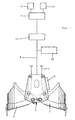
- Fig. 1 shows the gripper 4 suspended on a rope 2, which as Rope grabs or motor grabs, especially as motor hydraulic grabs, is trained.
- the gripper 4 contains two in a known manner Swiveling gripper shells 6, 7, one not shown here Hydraulic motor and a control box 8 with electronic components.
- a special line is used to supply energy to the gripper 4 or a supply cable 5, which the gripper 4 at the lifting and Lowering movements over guide rollers is tracked.
- About these Line 5 is the supply of the built in the gripper Transducers and their evaluation electronics in the switch box 8.
- the measured values are transmitted via one in the same line 5 Integrated, especially two-wire, bus line.
- the integrated bus line data is transferred in one freely programmed control system 10 evaluated and subsequently on a computer 12, in particular an industrial PC 12 with a screen 14 transferred.
- the computer 12 contains a visualization program for the preparation of the data, in clear symbols to be displayed on the screen 14.
- Limit values can be specified and deviations from permissible values are immediately displayed to the operator optically or acoustically and at If necessary, the limit is exceeded immediately Switch off the drive.
- the computer 12 is also a printer 16 assigned to optionally connect every measured value, every message to be able to output with date and time.
- a control device 18 For the preferably in Gripper 4 arranged motor, by means of which the movement of the Gripper shells 6, 7 can be carried out, a control device 18 intended.
- This control device 18 contains appropriately a frequency converter, with a speed control Protection of the mechanics and adjustment of the engine speed enables and due to the variable speed cycle times and delivery rate are adaptable depending on the material.
- Fig. 2 shows a block diagram of the gripper 4 with an integrated data transmission system 20 with PROFIBUS.
- Via special line 5, which is preferably designed as a CORDAFLEX cable and in which the bus line is integrated will be connected to the data transmission system 20 transferred data or measured values of the following to the programmable sensor to be explained in detail Control system 10 transmitted.
- the oil pan 21 and the electronic control box 8 is in expediently provided a number of sensors.
- a sensor 23 for the oil temperature In the oil pan 21 is a sensor 23 for the oil temperature.
- a sensor 24 in the gripper is used for filter monitoring and in the oil pan 21 there is also a sensor 25 for the oil level intended.
- the degree of contamination of the Oil filter permanently recorded by means of differential pressure monitoring and further displayed by means of the computer 12 and / or screen. So a necessary replacement of the oil filter can be recognized in good time and the filter must only be replaced when the specified degree of pollution has been reached. In comparison with a filter exchange after predetermined time intervals achieved a significant improvement in operation.
- the gripper 4 also contains a transmitter 26 for the position indicator of the Greiferschalen. Furthermore, there is a sensor 27 for the engine temperature, especially for the detection of engine overtemperature intended.
- the screen can display the current position or inclination of the gripper 4 are monitored and in practice This can prevent a gripper from tipping over become.
- a predeterminable limit value of the inclination in particular the drive for lowering the gripper is switched off and / or the Motor for lifting the gripper can be switched on.
- the gripper shells are switched off.
- transducer 29 for detecting the closing pressure
- transmitter 30 for detecting the opening pressure
- the transducer 26 for the detection of the gripper shell position is preferably as an angle encoder and / or absolute encoder educated. Above all, the limit values for the delivery and delivery are adjustable by means of the computer 12, so that a setting on The gripper 4 itself is only required when the sensor is replaced is.
- the position of the gripper shells is always up to date on the Screen 14 of the calculator 12 displayed and as a result of the exact Knowledge of the position of the gripper shells 6, 7 is a defined one Shutdown in the end positions and reliable detection of heavy wood allows.
- the sensor 25 for the oil level is preferred as a level sensor to record the oil level in the oil pan of the Hydraulic system trained.
- the limit values for warning, minimum level and maximum level can be directly on the screen of the computer 10 be changed so that a setting on the gripper 4 itself is not is required. Since the level of the oil pan 21 is always up to date Screen 14 of calculator 10 is displayed, both a Oil loss as well as a possible penetration of water into the Oil pan 21 can be recognized very early.
- the transmitter 23 for measuring the oil temperature is particularly designed as a PT 100 sensor and the so detected Temperature is displayed as an absolute value on the screen 14 of the computer 10 is displayed.
- the limit values for the oil temperature can also be set directly can be set via the computer 10, so that in turn a complex adjustment on the encoder or gripper itself is not necessary is.
- the transducers 29 and 30 for the closing pressure and Opening pressure of the gripper shells are particularly on the respective Cylinders of the gripper motor are arranged and are preferred over Pressure transmitter detected and as absolute values on the screen 14 of the computer 12 brought to the display. Also for the closing pressure and the opening pressure are the limit values by means of the computer 10 adjustable, without intervention on the gripper.
- the limit indicator 28 for the inclination of the gripper in expediently its inclination uniaxially across the rope suspension recorded and monitored and always up to date on the screen 14 of the Calculator 10 displayed.
- the limits for the allowable slope are likewise adjustable by means of the computer 10. If exceeded the allowable angle of inclination is within the scope of the invention the lowering movement of the gripper is switched off and thus with a high degree of safety tilting of the gripper 4 prevented. There will also be damage the traverse on which the gripper can be suspended is, the ropes 2, the special line or the supply cable 5 as a result prevent the gripper from tipping over with a high degree of certainty.
- the sensor 24 is used for filter monitoring and detection the degree of contamination of the oil filter, preferably by means of differential pressure monitoring. Via the computer 12 takes place on the Screen 14 a display, and a possibly necessary replacement of the Filters can be recognized in time. The filter must be replaced can only be carried out if the specified degree of contamination is reached. This will result in significant operational Advantages compared to a routine exchange according to specified Time intervals reached.
- the computer 12 connected to the control system 10 with a screen 14 and printer 16 enables visualization and if necessary Output of the data or measured values recorded in this way.
- the setting the limit values for the mentioned measured values are given in expediently by means of the computer 12 without the gripper 4th interventions would be required.
- the changed limit values are immediately transferred to the control program.
- the calculator 12 contains a limit point 33 for the oil temperature, a limit point 34 for filter monitoring, a limit value point 35 for the Oil level.
- the respective limit values are on the Screen 14 can be displayed and by means of an input unit, in particular the keyboard or mouse of the computer in the required Enterable accordingly.
Landscapes
- Engineering & Computer Science (AREA)
- Mechanical Engineering (AREA)
- Mining & Mineral Resources (AREA)
- Civil Engineering (AREA)
- General Engineering & Computer Science (AREA)
- Structural Engineering (AREA)
- Control And Safety Of Cranes (AREA)
- Earth Drilling (AREA)
- Arrangements For Transmission Of Measured Signals (AREA)
- Load-Engaging Elements For Cranes (AREA)
- Testing And Monitoring For Control Systems (AREA)
Claims (11)
- Dispositif de surveillance d'un grappin motorisé submersible (4), lequel est suspendu à un filin (2) et dont le moteur est relié par un câble à un dispositif de commande (18), au moins un générateur de valeurs mesurées (23 à 30) associé au grappin (4) étant prévu et au moins une valeur mesurée dudit générateur de valeurs mesurées (23 à 30) pouvant être représentée,
caractérisé en ce que sur le grappin (4) est disposé un système de transmission de données (20), auquel est relié le générateur de valeurs mesurées (23 à 30),
que le câble comprend une ligne de bus (5) intégrée, par laquelle le système de transmission de données (20) est relié à un système de commande dans lequel les données correspondant à la valeur mesurée peuvent être analysées et lequel est relié au dispositif de commande (18),
et que les données transmises par la ligne de bus intégrée (5) peuvent être transmises en continuation à un ordinateur (12), auquel est relié un écran (14) pour la représentation optique ou une imprimante (16) pour l'édition de la valeur mesurée. - Dispositif de surveillance selon la revendication 1, caractérisé en ce qu'au moyen de l'ordinateur (12) il est possible de prédéterminer une valeur seuil pour la valeur mesurée, laquelle peut être saisie par le générateur de valeurs mesurées (23 à 30).
- Dispositif de surveillance selon l'une des revendications 1 et 2, caractérisé en ce que le système de transmission de données (20) comprend un PROFIBUS.
- Dispositif de surveillance selon l'une des revendications 1 à 3, caractérisé en ce que le système de transmission de données (20) est disposé dans un boítier électrique (8) du grappin (4).
- Dispositif de surveillance selon l'une des revendications 1 à 4, caractérisé en ce que le système de commande (10) est réalisé sous forme de système d'automate programmable.
- Dispositif de surveillance selon l'une des revendications 1 à 5, caractérisé en ce que la ligne de bus (5) est réalisée sous forme de ligne de bus bifilaire.
- Dispositif de surveillance selon l'une des revendications 1 à 6, caractérisé en ce que le dispositif de commande (18) comprend un convertisseur de fréquence.
- Dispositif de surveillance selon l'une des revendications 1 à 7, caractérisé en ce que l'ordinateur (12) présente des positions de valeurs seuils (33 à 39) pour la prédétermination de valeurs seuils des grandeurs de mesures pouvant être saisies par le générateur de valeurs mesurées (23 à 30).
- Dispositif de surveillance selon l'une des revendications 1 à 8, caractérisé en ce que l'inclinaison du grappin peut--être-saisie au moyen du générateur de valeurs mesurées (28) et/ou que la position des godets de grappin (6, 7) peut être saisie au moyen du générateur de valeurs mesurées (26).
- Dispositif de surveillance selon l'une des revendications 1 à 9, caractérisé en ce que dans un carter d'huile (21) du grappin (4) est monté le générateur de valeurs mesurées (23) pour la température d'huiler et/ou le générateur de valeurs mesurées (24) pour une surveillance de filtre et/ou le générateur de valeurs mesurées (25) pour le niveau d'huile dans le carter d'huile (21).
- Dispositif de surveillance selon l'une des revendications 1 à 10, caractérisé en ce que le grappin (4) comprend le générateur de valeurs mesurées (25) pour la surveillance du niveau d'huile et/ou le générateur de valeurs mesurées (27) pour saisir la température du moteur et/ou le générateur de valeurs mesurées (29) pour la pression de fermeture__ et/ou le générateur de valeurs mesurées (30) pour saisir la pression d'ouverture des godets de grappin (6, 7).
Applications Claiming Priority (2)
| Application Number | Priority Date | Filing Date | Title |
|---|---|---|---|
| DE19806816 | 1998-02-18 | ||
| DE19806816A DE19806816B4 (de) | 1998-02-18 | 1998-02-18 | Motor-Unterwassergreifer mit Überwachungseinrichtung |
Publications (2)
| Publication Number | Publication Date |
|---|---|
| EP0937675A1 EP0937675A1 (fr) | 1999-08-25 |
| EP0937675B1 true EP0937675B1 (fr) | 2003-04-16 |
Family
ID=7858196
Family Applications (1)
| Application Number | Title | Priority Date | Filing Date |
|---|---|---|---|
| EP99101180A Expired - Lifetime EP0937675B1 (fr) | 1998-02-18 | 1999-01-22 | Dispositif de surveillance pour grappin motorisé submersible |
Country Status (3)
| Country | Link |
|---|---|
| US (1) | US6134815A (fr) |
| EP (1) | EP0937675B1 (fr) |
| DE (2) | DE19806816B4 (fr) |
Cited By (3)
| Publication number | Priority date | Publication date | Assignee | Title |
|---|---|---|---|---|
| FR2859717A1 (fr) * | 2003-07-03 | 2005-03-18 | Wolfgang Rohr Gmbh & Co Kg | Benne preneuse, en particulier benne preneuse d'immersion a moteur |
| CN105438976A (zh) * | 2015-12-30 | 2016-03-30 | 上海佩纳沙士吉打机械有限公司 | 液压抓斗智能监测系统 |
| EP3725950B1 (fr) | 2019-04-18 | 2022-09-14 | BAUER Maschinen GmbH | Benne de forage et procédé de fabrication d'une parois dans le sol |
Families Citing this family (14)
| Publication number | Priority date | Publication date | Assignee | Title |
|---|---|---|---|---|
| DE19900279C1 (de) * | 1999-01-07 | 2001-02-01 | Wolfgang Rohr | Verfahren und Vorrichtung zur Rückgewinnung von Feinsand von einem schwimmenden Gewinnungsgerät |
| DE10025603A1 (de) * | 2000-05-24 | 2001-11-29 | Pat Gmbh | Überwachungs- und Steuereinrichtung für Bau- oder Industriefahrzeuge |
| FR2953862B1 (fr) * | 2009-12-11 | 2011-12-16 | Ecl | Dispositif destine a collecter des debris solides dans une cuve d'electrolyse destinee a la production d'aluminium |
| WO2014169029A1 (fr) * | 2013-04-09 | 2014-10-16 | Anvil Attachments | Surveillance d'un mécanisme de saisie |
| EP2952634B1 (fr) * | 2014-06-03 | 2019-03-13 | Enel Produzione S.p.A. | Dispositif preneur avec un système de détection de l'état ouvert ou fermé |
| NL2014296B1 (nl) * | 2015-02-13 | 2016-10-13 | Hendricus Liet Cornelis | Inrichting voor het losmaken van veevoer. |
| CN106586823A (zh) * | 2016-12-09 | 2017-04-26 | 长沙桑铼特农业机械设备有限公司 | 一种组合式抓斗及拖拉机 |
| CN106741647B (zh) * | 2017-02-08 | 2018-10-26 | 哈尔滨工程大学 | 一种uuv海底驻留的锚泊装置及方法 |
| DE102017117637A1 (de) * | 2017-08-03 | 2019-02-07 | Turck Holding Gmbh | Sensorgerät und Verfahren zur Generierung eines Zustandssignals |
| JP6869510B2 (ja) * | 2017-11-30 | 2021-05-12 | ダイハツディーゼル株式会社 | 浚渫船用エンジンの過給システム |
| NL2025060B1 (en) * | 2020-03-05 | 2021-10-14 | Verstegen Grijpers B V | Grab monitoring device |
| CN112663715B (zh) * | 2020-12-28 | 2022-11-04 | 中国三峡建设管理有限公司 | 一种水下清淤系统及方法 |
| FR3120096A1 (fr) * | 2021-02-24 | 2022-08-26 | Safran Aircraft Engines | Procédé et dispositif de génération d’alarme pour la surveillance d’un filtre à huile dans un aéronef |
| CN119850046B (zh) * | 2025-03-20 | 2025-06-20 | 中港疏浚有限公司 | 一种抓斗船施工质量分析智能管理系统 |
Family Cites Families (11)
| Publication number | Priority date | Publication date | Assignee | Title |
|---|---|---|---|---|
| DE2110352B2 (de) * | 1971-03-04 | 1978-07-13 | Demag Ag, 4100 Duisburg | Hydraulikgreifer mit einem elektrisch gesteuerten Motor |
| DE3536472A1 (de) * | 1985-10-12 | 1987-04-16 | Rohr Gmbh | Tiefenmesseinrichtung fuer krananlagen |
| US5189605A (en) * | 1989-10-10 | 1993-02-23 | The Manitowoc Company, Inc. | Control and hydraulic system for a liftcrane |
| US5297019A (en) * | 1989-10-10 | 1994-03-22 | The Manitowoc Company, Inc. | Control and hydraulic system for liftcrane |
| US5964256A (en) * | 1990-04-27 | 1999-10-12 | K.J. Manufacturing | Apparatus and method for changing oil in an internal combustion engine and simultaneously determining engine oil consumption and wear |
| DE4215739C2 (de) * | 1992-05-13 | 1995-11-30 | Kleinewefers Gmbh | Verfahren und Vorrichtung zum Beschicken und Entnehmen von mit einer Materialbahn bewickelten Rollen in einer einen Rollenträger mit mehreren Rollenplätzen aufweisenden Maschine zum Verarbeiten der Materialbahn, insbesondere einer Druckmaschine |
| US5443294A (en) * | 1993-09-22 | 1995-08-22 | Hawco Manufacturing Co. | Single-line clamshell bucket |
| US5553404A (en) * | 1994-05-17 | 1996-09-10 | Bergeron; Raymond C. | Power bucket |
| DE19514050C2 (de) * | 1995-04-13 | 1999-06-02 | Bruger & Fischer Krananlagen U | Verfahren und Vorrichtung zum Erfassen von Belastungen von Hub- und Zugeinrichtungen |
| US5995916A (en) * | 1996-04-12 | 1999-11-30 | Fisher-Rosemount Systems, Inc. | Process control system for monitoring and displaying diagnostic information of multiple distributed devices |
| US6024145A (en) * | 1998-04-08 | 2000-02-15 | Ackles; Gary | Articulated boom and head for manipulating objects under water |
-
1998
- 1998-02-18 DE DE19806816A patent/DE19806816B4/de not_active Expired - Lifetime
-
1999
- 1999-01-22 EP EP99101180A patent/EP0937675B1/fr not_active Expired - Lifetime
- 1999-01-22 DE DE59905026T patent/DE59905026D1/de not_active Expired - Lifetime
- 1999-02-11 US US09/248,344 patent/US6134815A/en not_active Expired - Lifetime
Cited By (3)
| Publication number | Priority date | Publication date | Assignee | Title |
|---|---|---|---|---|
| FR2859717A1 (fr) * | 2003-07-03 | 2005-03-18 | Wolfgang Rohr Gmbh & Co Kg | Benne preneuse, en particulier benne preneuse d'immersion a moteur |
| CN105438976A (zh) * | 2015-12-30 | 2016-03-30 | 上海佩纳沙士吉打机械有限公司 | 液压抓斗智能监测系统 |
| EP3725950B1 (fr) | 2019-04-18 | 2022-09-14 | BAUER Maschinen GmbH | Benne de forage et procédé de fabrication d'une parois dans le sol |
Also Published As
| Publication number | Publication date |
|---|---|
| DE19806816B4 (de) | 2005-04-14 |
| DE59905026D1 (de) | 2003-05-22 |
| EP0937675A1 (fr) | 1999-08-25 |
| DE19806816A1 (de) | 1999-08-26 |
| US6134815A (en) | 2000-10-24 |
Similar Documents
| Publication | Publication Date | Title |
|---|---|---|
| EP0937675B1 (fr) | Dispositif de surveillance pour grappin motorisé submersible | |
| DE69821791T3 (de) | Vorrichtung zum überwachen des lichtbogenschweissens | |
| DE4234654A1 (de) | Diagnosesystem für Roboter und Anwendungsverfahren dafür | |
| DE112013000155B4 (de) | Hydraulikzylinderhubbetriebsdiagnoseunterstützungsvorrichtung und Hydraulikzylinderhubbetriebsdiagnoseunterstützungsverfahren | |
| DE2709569A1 (de) | Zentrifuge mit einer einrichtung zum aufspueren und anzeigen von torsionsschwingungen | |
| DE112006000695T5 (de) | Automatisches Maschinensystem und drahtloses Kommunikationsverfahren für dasselbe | |
| DE102007032715A1 (de) | System und Verfahren zur Überwachung des Datenverkehrs bei einem Feldbus | |
| DE112019002906T5 (de) | Baumaschine | |
| DE112016006999T5 (de) | System und verfahren zum sammeln von betriebsschwingungsdaten für eine bergbaumaschine | |
| EP4017826A1 (fr) | Unité de commande et procédé d'actionnement d'un moyen de transport | |
| DE60029018T2 (de) | Ladegeschirr | |
| EP2160349B1 (fr) | Agencement, module et procédé pour le fonctionnement sûr d'une installation | |
| EP0849213B2 (fr) | Grue à tour | |
| EP0364994A1 (fr) | Commande de grue | |
| DE19931302A1 (de) | Kontinuierlich verstellbarer Kran | |
| EP0447511B1 (fr) | Procede et systeme pour surveiller une installation, telle qu'une grue automobile, un gros excavateur ou similaire | |
| DE10233873B4 (de) | Steuerung für eine Krananlage, insbesondere einen Containerkran | |
| DE10228389B4 (de) | Schwingungssensor und Verfahren zur Zustandsüberwachung von rotierenden Bauteilen und Lagern | |
| JP7141850B2 (ja) | 杭打機及びアースドリルの施工管理装置 | |
| EP2601490A1 (fr) | Procédé de surveillance des composants moteurs d'une grosse pelleteuse hydraulique | |
| DE102020208295A1 (de) | Ausfallvorhersagesystem | |
| DE102020203598A1 (de) | Steuersystem für eine industriemaschine | |
| DE19611573A1 (de) | Vorrichtung und Verfahren zum Bewegen von Bauwerken | |
| DE102018123150B4 (de) | Drehgeber und Verfahren zum Betrieb eines Hebezeugs | |
| EP2518577A1 (fr) | Méthode et appareil pour faire fonctionner un positionneur avec la capacité de communiquer en mode digital e analogue à travers une seule boucle de courrant |
Legal Events
| Date | Code | Title | Description |
|---|---|---|---|
| PUAI | Public reference made under article 153(3) epc to a published international application that has entered the european phase |
Free format text: ORIGINAL CODE: 0009012 |
|
| AK | Designated contracting states |
Kind code of ref document: A1 Designated state(s): CH DE FR IT LI |
|
| AX | Request for extension of the european patent |
Free format text: AL;LT;LV;MK;RO;SI |
|
| 17P | Request for examination filed |
Effective date: 19990811 |
|
| AKX | Designation fees paid |
Free format text: CH DE FR IT LI |
|
| 17Q | First examination report despatched |
Effective date: 20011109 |
|
| GRAH | Despatch of communication of intention to grant a patent |
Free format text: ORIGINAL CODE: EPIDOS IGRA |
|
| GRAH | Despatch of communication of intention to grant a patent |
Free format text: ORIGINAL CODE: EPIDOS IGRA |
|
| GRAA | (expected) grant |
Free format text: ORIGINAL CODE: 0009210 |
|
| AK | Designated contracting states |
Designated state(s): CH DE FR IT LI |
|
| REG | Reference to a national code |
Ref country code: CH Ref legal event code: EP |
|
| REF | Corresponds to: |
Ref document number: 59905026 Country of ref document: DE Date of ref document: 20030522 Kind code of ref document: P |
|
| REG | Reference to a national code |
Ref country code: CH Ref legal event code: NV Representative=s name: PATENTANWALT DIPL. ING. WOLFGANG HEISEL |
|
| ET | Fr: translation filed | ||
| PLBE | No opposition filed within time limit |
Free format text: ORIGINAL CODE: 0009261 |
|
| STAA | Information on the status of an ep patent application or granted ep patent |
Free format text: STATUS: NO OPPOSITION FILED WITHIN TIME LIMIT |
|
| 26N | No opposition filed |
Effective date: 20040119 |
|
| PG25 | Lapsed in a contracting state [announced via postgrant information from national office to epo] |
Ref country code: IT Free format text: LAPSE BECAUSE OF NON-PAYMENT OF DUE FEES Effective date: 20050122 |
|
| REG | Reference to a national code |
Ref country code: FR Ref legal event code: TP Ref country code: FR Ref legal event code: CD |
|
| REG | Reference to a national code |
Ref country code: CH Ref legal event code: PUE Owner name: ROHR BAGGER GMBH Free format text: ROHR GMBH#SPEYERERSTRASSE 74-80#D-67166 OTTERSTADT (DE) -TRANSFER TO- ROHR BAGGER GMBH#ROTTERDAMER STR. 15#68219 MANNHEIM (DE) |
|
| PGRI | Patent reinstated in contracting state [announced from national office to epo] |
Ref country code: IT Effective date: 20091201 |
|
| REG | Reference to a national code |
Ref country code: FR Ref legal event code: PLFP Year of fee payment: 18 |
|
| REG | Reference to a national code |
Ref country code: FR Ref legal event code: PLFP Year of fee payment: 19 |
|
| REG | Reference to a national code |
Ref country code: DE Ref legal event code: R082 Ref document number: 59905026 Country of ref document: DE Representative=s name: REBLE & KESSELHUT PARTNERSCHAFTSGESELLSCHAFT V, DE |
|
| REG | Reference to a national code |
Ref country code: FR Ref legal event code: PLFP Year of fee payment: 20 |
|
| PGFP | Annual fee paid to national office [announced via postgrant information from national office to epo] |
Ref country code: CH Payment date: 20180125 Year of fee payment: 20 Ref country code: DE Payment date: 20180124 Year of fee payment: 20 |
|
| REG | Reference to a national code |
Ref country code: CH Ref legal event code: PCAR Free format text: NEW ADDRESS: HOLEESTRASSE 87, 4054 BASEL (CH) |
|
| PGFP | Annual fee paid to national office [announced via postgrant information from national office to epo] |
Ref country code: IT Payment date: 20180126 Year of fee payment: 20 Ref country code: FR Payment date: 20180124 Year of fee payment: 20 |
|
| REG | Reference to a national code |
Ref country code: DE Ref legal event code: R071 Ref document number: 59905026 Country of ref document: DE |
|
| REG | Reference to a national code |
Ref country code: CH Ref legal event code: PL |