EP0937820B1 - Barrière de sécurité - Google Patents
Barrière de sécurité Download PDFInfo
- Publication number
- EP0937820B1 EP0937820B1 EP99109719A EP99109719A EP0937820B1 EP 0937820 B1 EP0937820 B1 EP 0937820B1 EP 99109719 A EP99109719 A EP 99109719A EP 99109719 A EP99109719 A EP 99109719A EP 0937820 B1 EP0937820 B1 EP 0937820B1
- Authority
- EP
- European Patent Office
- Prior art keywords
- barrier
- drive shaft
- installation according
- locking arm
- arm
- Prior art date
- Legal status (The legal status is an assumption and is not a legal conclusion. Google has not performed a legal analysis and makes no representation as to the accuracy of the status listed.)
- Expired - Lifetime
Links
- 230000004888 barrier function Effects 0.000 title claims description 15
- 239000012780 transparent material Substances 0.000 claims description 2
- 238000009434 installation Methods 0.000 claims 6
- 238000005286 illumination Methods 0.000 claims 2
- 230000000903 blocking effect Effects 0.000 description 2
- 230000007257 malfunction Effects 0.000 description 2
- 239000004020 conductor Substances 0.000 description 1
- 239000000463 material Substances 0.000 description 1
- NJPPVKZQTLUDBO-UHFFFAOYSA-N novaluron Chemical compound C1=C(Cl)C(OC(F)(F)C(OC(F)(F)F)F)=CC=C1NC(=O)NC(=O)C1=C(F)C=CC=C1F NJPPVKZQTLUDBO-UHFFFAOYSA-N 0.000 description 1
- 230000003014 reinforcing effect Effects 0.000 description 1
Images


Classifications
-
- E—FIXED CONSTRUCTIONS
- E01—CONSTRUCTION OF ROADS, RAILWAYS, OR BRIDGES
- E01F—ADDITIONAL WORK, SUCH AS EQUIPPING ROADS OR THE CONSTRUCTION OF PLATFORMS, HELICOPTER LANDING STAGES, SIGNS, SNOW FENCES, OR THE LIKE
- E01F13/00—Arrangements for obstructing or restricting traffic, e.g. gates, barricades ; Preventing passage of vehicles of selected category or dimensions
- E01F13/02—Arrangements for obstructing or restricting traffic, e.g. gates, barricades ; Preventing passage of vehicles of selected category or dimensions free-standing; portable, e.g. for guarding open manholes ; Portable signs or signals specially adapted for fitting to portable barriers
- E01F13/028—Flexible barrier members, e.g. cords; Means for rendering same conspicuous; Adapted supports, e.g. with storage reel
-
- E—FIXED CONSTRUCTIONS
- E01—CONSTRUCTION OF ROADS, RAILWAYS, OR BRIDGES
- E01F—ADDITIONAL WORK, SUCH AS EQUIPPING ROADS OR THE CONSTRUCTION OF PLATFORMS, HELICOPTER LANDING STAGES, SIGNS, SNOW FENCES, OR THE LIKE
- E01F13/00—Arrangements for obstructing or restricting traffic, e.g. gates, barricades ; Preventing passage of vehicles of selected category or dimensions
- E01F13/04—Arrangements for obstructing or restricting traffic, e.g. gates, barricades ; Preventing passage of vehicles of selected category or dimensions movable to allow or prevent passage
- E01F13/06—Arrangements for obstructing or restricting traffic, e.g. gates, barricades ; Preventing passage of vehicles of selected category or dimensions movable to allow or prevent passage by swinging into open position about a vertical or horizontal axis parallel to the road direction, i.e. swinging gates
-
- E—FIXED CONSTRUCTIONS
- E05—LOCKS; KEYS; WINDOW OR DOOR FITTINGS; SAFES
- E05F—DEVICES FOR MOVING WINGS INTO OPEN OR CLOSED POSITION; CHECKS FOR WINGS; WING FITTINGS NOT OTHERWISE PROVIDED FOR, CONCERNED WITH THE FUNCTIONING OF THE WING
- E05F1/00—Closers or openers for wings, not otherwise provided for in this subclass
- E05F1/08—Closers or openers for wings, not otherwise provided for in this subclass spring-actuated, e.g. for horizontally sliding wings
- E05F1/10—Closers or openers for wings, not otherwise provided for in this subclass spring-actuated, e.g. for horizontally sliding wings for swinging wings, e.g. counterbalance
- E05F1/12—Mechanisms in the shape of hinges or pivots, operated by springs
Definitions
- the invention relates to a shut-off device for a lane, with a pedestal, with a locking arm arranged on a horizontal drive shaft, which between a horizontal locking position and an upward release position is pivotable, and with a swivel drive, possibly also a Opening movement of the locking arm supporting compensating spring element is provided is.
- the locking arm has two hinged together Share on.
- shut-off device is already known from the document DE-A-3 719 912.
- this drive device an endless chain is used for parallel guidance of the free locking arm part.
- the invention now looks specifically for parking garages and other buildings inside lanes to be blocked off a version in which the locking arm is articulated has interconnected parts, the free arm part during the pivoting is guided essentially parallel to the locked position.
- the locking arm is articulated has interconnected parts, the free arm part during the pivoting is guided essentially parallel to the locked position.
- Passenger cars also have a lane with a clear height of e.g. 2 m and one Width of e.g. 2.50 m can be blocked.
- the first locking arm part is provided. Since this cable only comprises one cable length, it is therefore cannot be subjected to pressure, it is provided according to the invention that the parallel guide on the pivot of the free locking arm part a return spring having.
- the other end of the rope is preferably one in the drive shaft axis lying rope pulley out of the locking arm to the outside and on the Stand column fixed.
- the lane should can be opened as easily as possible.
- a preferred embodiment sees for this purpose, that the first locking arm part locked in place at the end region of the drive shaft Has flange.
- the detachable attachment of the support flange can be preferred realize in such a way that the support flange acted radially resiliently Has locking elements, and distributed in the end region of the drive shaft over the circumference Locking recesses are provided.
- shut-off device is characterized in that at least the first locking arm part made of transparent material exists and has an internal lighting device.
- a particularly simple embodiment provides that the lighting device has a light source arranged at the end region of the drive shaft, which light source Lock arm illuminated.
- the locking arm itself can therefore be easily removed and be reassembled.
- a shut-off device for a lane for example a barrier in one Parking garage or the like.
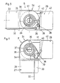
- the drive shaft 2 carries on her end protruding from the column head 30 by means of a quick-release fastener 12 attached locking arm 9, the quick release 12 removing the locking arm 9th allowed in case of power failure or other malfunctions.
- a compensating spring element 8 supporting an electric motor 6 is the drive shaft 2 assigned so that in a relaxed zero position 0 or in the middle of a relaxed zero position of the locking arm 9 under the position shown in Fig. 1 about 45 ° to 60 ° upwards.
- the balancing spring element 8 supports and accelerates the opening movement of the locking arm 9 from the horizontal Lock position S up to the relaxed zero position 0 and dampens the subsequent one Movement to the upper end position F.
- the closing movement is achieved by the also in the upper end position F biased compensation spring element 8 to Zero position or the zero position range accelerated and then braked.
- the locking arm 9 is in particular made of two half-profile parts 54 formed of light-conducting material, between which in the connection area the drive shaft 2 has a reinforcing, in particular likewise two-part core 51 is provided.
- the core contains a bearing pin 52 for a pulley 53, over the one rope 32 explained in more detail below, the end 31 of the locking arm 9 emerges, as can be seen in FIG. 2, and on the column head 30 or the column 1 is fixed.
- the two half-profile parts 54 are in a support flange 23 of the quick-release fastener 12 embedded and covered to the outside by a cap 48.
- the supporting flange 23 has a ring of locking elements 44, in particular balls, which in a ring of bores 43 are engaged in the end region 47 of the drive shaft 2, wherein they are acted upon radially to the drive shaft 2 by springs 45.
- the one shown Ball locking between the support flange 23 and the drive shaft 2 allows both the simple removal of the locking arm 9 in the event of faults as well Rotation of obstacles in the swivel path, for example one in the lane stationary vehicle.
- the locking arm 9 is formed in two parts, because the lane is available Height is too low, and consists of a, with the flange 23 of the drive shaft 2nd connectable first part 27, a free, second part 29 and an intermediate Joint 28, 41 together.
- the free part 29 moves approximately parallel to the horizontal locking position upwards, i.e. it kinks during the opening movement on the first part 27. This is done using a parallel guide Help of the rope 32 running within the first part 27.
- One end 31 of the Rope 32 is, as mentioned, fixed to the column 1 or to the column head 30, and that other end connected to a locking lever 39 which is a bearing hook 38 of the Hinge bracket 41 of the second locking arm part 29 is pivotable.
- the locking lever 39 has a spring hook 40, which has a latching web 35 on the joint plate 28 of the engages behind the first locking arm 27 in the locking position 5 of the locking arm 9.
- the opening movement pivots the locking arm 9 in the extended position until the the column 1 attached rope 32 has pivoted the locking lever 39 so far that the Spring hook 40 is disengaged from the locking web 35. This is after an opening angle the case of a few degrees.
- the locking arm part 27 is translucent or transparent, so that at least the The blocking arm part 27 is illuminated by a lighting device 50 which, as in FIG. 3 shows, is arranged on the front end portion 47 of the drive shaft 2.
- the light-guiding Material of the half-profile parts 54 makes the locking arm 9 appear as a luminous bar, the two half-profile parts 54 can also be colored differently.
- the Power is supplied via a cable 49 which through an axial bore 46 Drive shaft 2 is fed into the central region of the support flange 23.
Landscapes
- Engineering & Computer Science (AREA)
- Architecture (AREA)
- Civil Engineering (AREA)
- Structural Engineering (AREA)
- Refuge Islands, Traffic Blockers, Or Guard Fence (AREA)
- Power-Operated Mechanisms For Wings (AREA)
- Buildings Adapted To Withstand Abnormal External Influences (AREA)
- Devices For Checking Fares Or Tickets At Control Points (AREA)
- Push-Button Switches (AREA)
- Soil Working Implements (AREA)
- Operating, Guiding And Securing Of Roll- Type Closing Members (AREA)
Claims (6)
- Barrière de sécurité pour une voie de circulation, avec une colonne sur pied (1), avec un bras de blocage (9) disposé sur un arbre d'entraínement (2) horizontal, qui présente deux pièces (27, 29) reliées entre elles de façon articulée et peut être basculée entre une position de blocage (S) horizontale et une position de déblocage (F) vers le haut, le bras de blocage (29) libre étant guidé pendant le basculement de façon sensiblement parallèle à la position de blocage (S), et avec une commande de basculement, un élément à ressort d'équilibrage (8) soutenant le mouvement d'ouverture du bras de blocage (9) étant prévu également le cas échéant, caractérisée en ce que le guidage parallèle présente une tirette avec un câble (32) et un ressort de rappel (37) sur l'articulation de rotation (28, 41) de la partie libre du bras de blocage (29).
- Barrière de sécurité selon la revendication 1, caractérisée en ce que l'extrémité (31) du câble (32) est guidée à partir de la première partie du bras de blocage (9) vers l'extérieur au moyen d'une poulie (53) disposée sur l'axe de l'arbre d'entraínement (2) et est fixée sur la colonne sur pied (1).
- Barrière de sécurité selon la revendication 1 ou 2, caractérisée en ce que la première partie du bras de blocage (27) présente une bride support (23) encliquetée sur la zone d'extrémité (47) de l'arbre d'entraínement (2).
- Barrière de sécurité selon la revendication 3, caractérisée en ce que la bride support (23) présente des éléments d'encliquetage (44) sollicités de façon élastique sur un plan radial et des évidements d'encliquetage (43) sont prévus dans la zone d'extrémité (47) de l'arbre d'entraínement (2) sur la périphérie.
- Barrière de sécurité selon l'une quelconque des revendications 1 à 4, caractérisée en ce qu'au moins la première partie du bras de blocage (27) est à base de matériau transparent et présente un dispositif d'éclairage (50) interne.
- Barrière de sécurité selon la revendication 5, caractérisée en ce que le dispositif d'éclairage (50) présente une source lumineuse disposée sur la zone d'extrémité de l'arbre d'entraínement (2).
Applications Claiming Priority (3)
| Application Number | Priority Date | Filing Date | Title |
|---|---|---|---|
| AT0048695A AT402311B (de) | 1995-03-20 | 1995-03-20 | Absperreinrichtung |
| AT48695 | 1995-03-20 | ||
| EP96905582A EP0760034B1 (fr) | 1995-03-20 | 1996-03-19 | Dispositif de barrage |
Related Parent Applications (2)
| Application Number | Title | Priority Date | Filing Date |
|---|---|---|---|
| EP96905582A Division EP0760034B1 (fr) | 1995-03-20 | 1996-03-19 | Dispositif de barrage |
| EP96905582.1 Division | 1996-09-26 |
Publications (3)
| Publication Number | Publication Date |
|---|---|
| EP0937820A2 EP0937820A2 (fr) | 1999-08-25 |
| EP0937820A3 EP0937820A3 (fr) | 2002-02-13 |
| EP0937820B1 true EP0937820B1 (fr) | 2003-10-29 |
Family
ID=3491879
Family Applications (4)
| Application Number | Title | Priority Date | Filing Date |
|---|---|---|---|
| EP99109721A Expired - Lifetime EP0937822B1 (fr) | 1995-03-20 | 1996-03-19 | Barrière de sécurité |
| EP99109719A Expired - Lifetime EP0937820B1 (fr) | 1995-03-20 | 1996-03-19 | Barrière de sécurité |
| EP96905582A Expired - Lifetime EP0760034B1 (fr) | 1995-03-20 | 1996-03-19 | Dispositif de barrage |
| EP99109720A Withdrawn EP0937821A3 (fr) | 1995-03-20 | 1996-03-19 | Barrière de sécurité |
Family Applications Before (1)
| Application Number | Title | Priority Date | Filing Date |
|---|---|---|---|
| EP99109721A Expired - Lifetime EP0937822B1 (fr) | 1995-03-20 | 1996-03-19 | Barrière de sécurité |
Family Applications After (2)
| Application Number | Title | Priority Date | Filing Date |
|---|---|---|---|
| EP96905582A Expired - Lifetime EP0760034B1 (fr) | 1995-03-20 | 1996-03-19 | Dispositif de barrage |
| EP99109720A Withdrawn EP0937821A3 (fr) | 1995-03-20 | 1996-03-19 | Barrière de sécurité |
Country Status (5)
| Country | Link |
|---|---|
| US (1) | US5813796A (fr) |
| EP (4) | EP0937822B1 (fr) |
| AT (1) | AT402311B (fr) |
| DE (4) | DE59610777D1 (fr) |
| WO (1) | WO1996029472A2 (fr) |
Cited By (1)
| Publication number | Priority date | Publication date | Assignee | Title |
|---|---|---|---|---|
| DE202013010383U1 (de) | 2013-11-15 | 2014-01-17 | Magnetic Autocontrol Gmbh | Schrankenanlage |
Families Citing this family (11)
| Publication number | Priority date | Publication date | Assignee | Title |
|---|---|---|---|---|
| SI9720054B (sl) * | 1996-10-30 | 2002-02-28 | Siemens Schweiz Ag | Prenosnik z gredjo za pogon zapornice |
| ES2160967T3 (es) * | 1997-07-17 | 2001-11-16 | Magnetic Autocontrol Gmbh | Dispositivo de accionamiento para una barrera de bloqueo. |
| US6179517B1 (en) | 1999-07-22 | 2001-01-30 | Kim L. Nelson | Traffic access control system |
| ITBS20010079U1 (it) * | 2001-09-24 | 2003-03-24 | Rib Srl | Barriera elettromeccanica |
| DE10359383A1 (de) * | 2003-12-18 | 2005-07-28 | Skidata Ag | Fahrzeugschranke |
| DE102008016070A1 (de) * | 2008-03-28 | 2009-10-01 | Skidata Ag | Schranke |
| DE202009017278U1 (de) | 2009-12-19 | 2010-05-06 | Magnetic Autocontrol Gmbh | Schrankenbaum |
| CN104652320B (zh) * | 2015-02-16 | 2017-05-31 | 张振滔 | 一种具有闸杆下杆缓冲功能的道闸机 |
| DE102019114513A1 (de) | 2018-05-30 | 2019-12-05 | Peter Fasel | Schrankensystem |
| CN115323956B (zh) * | 2022-08-15 | 2024-01-30 | 苏州金蚂蚁精密钣金有限公司 | 一种人行通道用闸机外壳 |
| CN116005588B (zh) * | 2023-03-14 | 2023-06-20 | 昆明理工大学 | 一种交通运输物流用超载阻截装置 |
Family Cites Families (23)
| Publication number | Priority date | Publication date | Assignee | Title |
|---|---|---|---|---|
| US2874493A (en) * | 1956-08-31 | 1959-02-24 | Ethel Scott | Automatic signal and barrier device for railroad crossings |
| GB934588A (en) * | 1961-08-15 | 1963-08-21 | Werk Signal Sicherungstech Veb | Improvements in or relating to barrier beams |
| DE1405696A1 (de) * | 1961-10-20 | 1969-03-27 | Graf Hagenburg Kg | Schranke zum Sperren von Strassen,Bahnuebergaengen,Baugruben oder sonstigen mit Unfallgefahr verbundenen Verkehrspunkten |
| FR1392127A (fr) * | 1964-04-06 | 1965-03-12 | Werkspoor Nv | Dispositif de barrage à barrière pivotante |
| FR1461210A (fr) * | 1965-12-22 | 1966-12-10 | Mécanisme de commande et de sécurité pour bras de barrière oscillante | |
| FR1501642A (fr) * | 1966-11-25 | 1967-11-10 | Bras pliant automatique pour barrière | |
| AT309922B (de) * | 1969-12-29 | 1973-09-10 | Hilti Ag | Überlastkupplung zur Übertragung eines gegen zunehmende Größe begrenzten Drehmomentes |
| FR2166272B1 (fr) * | 1972-01-05 | 1975-10-24 | Delot Pierre | |
| US3913717A (en) * | 1973-09-26 | 1975-10-21 | Qonaar Corp | Turnstile apparatus |
| GB1556157A (en) * | 1975-10-21 | 1979-11-21 | Warren Eng Ltd | Counterbalanced traffic barrier assemblies |
| US4090685A (en) * | 1977-02-22 | 1978-05-23 | Westinghouse Air Brake Company | Grade crossing assembly |
| DE3719912A1 (de) * | 1987-06-15 | 1988-12-29 | Malkmus Doernemann Carola | Schranke mit einem auf seiner laenge abwinkelbaren schrankenbaum |
| DE3743305A1 (de) * | 1987-12-21 | 1989-06-29 | Vdo Schindling | Schranke |
| DE3743304A1 (de) * | 1987-12-21 | 1989-06-29 | Vdo Schindling | Schranke |
| FR2639975A1 (fr) * | 1988-12-06 | 1990-06-08 | Entretien Fourn Mat Equip Indl | Dispositif pour le guidage et l'organisation de la circulation des pietons vers et sur les passages cloutes |
| US4897960A (en) * | 1989-01-03 | 1990-02-06 | General Signals, Inc. | Railroad crossing gate |
| FR2656884B1 (fr) * | 1990-01-11 | 1992-07-24 | Mignot Jean Marc | Dispositif d'entrainement en rotation de la lisse d'une barriere mobile. |
| GB2248482B (en) * | 1990-10-03 | 1994-07-06 | Kenneth Marden Henfrey | Combined spring balance,shock absorber and energy storage system for verticallyrotating beams such as traffic barriers |
| US5288164A (en) * | 1992-01-07 | 1994-02-22 | Nasatka Ralph G | Combined vehicle barrier |
| DE4215321A1 (de) * | 1992-01-20 | 1993-11-11 | 2K Kempe & Klaus Gmbh | Optische Absperrung |
| DE4202584A1 (de) * | 1992-01-30 | 1993-08-05 | Rhein Getriebe Gmbh | Antriebsvorrichtung fuer eine schranke oder dergleichen |
| US5469660A (en) * | 1994-01-10 | 1995-11-28 | Tamenne; Harry L. | Self-restoring railroad highway crossing gate device |
| US5466088A (en) * | 1994-01-24 | 1995-11-14 | Nasatka; Ralph G. | Vehicle barrier having a pivotal vehicle barricade and a cooperating pivotal signal barrier |
-
1995
- 1995-03-20 AT AT0048695A patent/AT402311B/de not_active IP Right Cessation
-
1996
- 1996-03-19 DE DE59610777T patent/DE59610777D1/de not_active Expired - Lifetime
- 1996-03-19 WO PCT/AT1996/000052 patent/WO1996029472A2/fr not_active Ceased
- 1996-03-19 EP EP99109721A patent/EP0937822B1/fr not_active Expired - Lifetime
- 1996-03-19 DE DE29620291U patent/DE29620291U1/de not_active Expired - Lifetime
- 1996-03-19 DE DE59610799T patent/DE59610799D1/de not_active Expired - Lifetime
- 1996-03-19 DE DE59604161T patent/DE59604161D1/de not_active Expired - Lifetime
- 1996-03-19 EP EP99109719A patent/EP0937820B1/fr not_active Expired - Lifetime
- 1996-03-19 US US08/737,664 patent/US5813796A/en not_active Expired - Lifetime
- 1996-03-19 EP EP96905582A patent/EP0760034B1/fr not_active Expired - Lifetime
- 1996-03-19 EP EP99109720A patent/EP0937821A3/fr not_active Withdrawn
Cited By (3)
| Publication number | Priority date | Publication date | Assignee | Title |
|---|---|---|---|---|
| DE202013010383U1 (de) | 2013-11-15 | 2014-01-17 | Magnetic Autocontrol Gmbh | Schrankenanlage |
| EP2907921A1 (fr) | 2013-11-15 | 2015-08-19 | Magnetic Autocontrol GmbH | Système de barrière |
| US9593454B2 (en) | 2013-11-15 | 2017-03-14 | Magnetic Autocontrol Gmbh | Barrier system |
Also Published As
| Publication number | Publication date |
|---|---|
| EP0760034B1 (fr) | 2000-01-12 |
| EP0937822A2 (fr) | 1999-08-25 |
| DE59610777D1 (de) | 2003-11-20 |
| DE29620291U1 (de) | 1997-05-07 |
| EP0937821A2 (fr) | 1999-08-25 |
| EP0937820A2 (fr) | 1999-08-25 |
| WO1996029472A3 (fr) | 1996-10-31 |
| US5813796A (en) | 1998-09-29 |
| DE59604161D1 (de) | 2000-02-17 |
| EP0937822B1 (fr) | 2003-10-15 |
| EP0760034A1 (fr) | 1997-03-05 |
| EP0937822A3 (fr) | 2002-02-13 |
| EP0937820A3 (fr) | 2002-02-13 |
| DE59610799D1 (de) | 2003-12-04 |
| WO1996029472A2 (fr) | 1996-09-26 |
| AT402311B (de) | 1997-04-25 |
| ATA48695A (de) | 1996-08-15 |
| EP0937821A3 (fr) | 2002-02-13 |
Similar Documents
| Publication | Publication Date | Title |
|---|---|---|
| EP0937820B1 (fr) | Barrière de sécurité | |
| DE69213232T2 (de) | Fallschutzgerat | |
| EP0292789B1 (fr) | Lucarne | |
| DE4118683C1 (fr) | ||
| DE60021244T2 (de) | Verkleidung einer Flugzeugtriebwerkgondel mit Verschlussfehleranzeiger | |
| DE60201883T2 (de) | Notbremsvorrichtung für ein kabelgezogenes oder aufgehängtes fahrzeug und fahrzeug mit einer notbremsvorrichtung | |
| DE2831862B1 (de) | Kupplungshaken fuer den Oberlenker einer Dreipunktanhaengevorrichtung | |
| DE68902268T2 (de) | Vorrichtung zum anbringen einer hebeeinrichtung an einen container oder dergl. | |
| DE3322268A1 (de) | Kran mit teleskopierbarem turm | |
| EP0282851B1 (fr) | Barrière de parking rabattable | |
| DE3433117C2 (de) | Turmkran mit dreiteiligem Ausleger | |
| DE3873671T2 (de) | Sicherheits-anseilsysteme, zugehoerige teile und ausruestungen. | |
| DE2555468A1 (de) | Schwenkbare trittstufe | |
| DE602004011747T2 (de) | Vorrichtung für Anzeigen eine korrekte Spannung des Sicherheitsgurtes | |
| EP0016325B1 (fr) | Dispositif de calage de charges extérieures suspendues à des aéronefs | |
| EP0565061B1 (fr) | Déverrouillage de sécurité pour panneaux de portes basculantes | |
| DE4019063C2 (fr) | ||
| DE3940491C1 (en) | Step flap for vehicle ramp - has adaptor with support to bear on ramp when latter pulled out for use | |
| EP0126263A2 (fr) | Dispositif d'accrochage ou de décrochage d'une masse de ballastage additionnelle à l'avant d'un tracteur agricole | |
| DE3929527A1 (de) | Verschluss, insbesondere fuer das faltdach eines fahrzeuges | |
| EP0722031A1 (fr) | Dispositif de surveillance d'un ressort de torsion précontraint | |
| DE2917023B2 (de) | Seilzug mit Toraufhänger und darin eingebauter Schlaffseilsicherung für ein Deckenglieder- oder Rolltor | |
| DE4309067A1 (de) | Schwenktüre für einen Personendurchgang | |
| DE19609830C1 (de) | Vorrichtung zum Aufhängen von Hebezeugen | |
| DE19639012A1 (de) | Mobile Drehbühne |
Legal Events
| Date | Code | Title | Description |
|---|---|---|---|
| PUAI | Public reference made under article 153(3) epc to a published international application that has entered the european phase |
Free format text: ORIGINAL CODE: 0009012 |
|
| AC | Divisional application: reference to earlier application |
Ref document number: 760034 Country of ref document: EP |
|
| AK | Designated contracting states |
Kind code of ref document: A2 Designated state(s): BE DE FR GB IT |
|
| PUAL | Search report despatched |
Free format text: ORIGINAL CODE: 0009013 |
|
| AK | Designated contracting states |
Kind code of ref document: A3 Designated state(s): BE DE FR GB IT |
|
| RIC1 | Information provided on ipc code assigned before grant |
Free format text: 7E 01F 13/06 A, 7F 16D 43/208 B |
|
| 17P | Request for examination filed |
Effective date: 20020621 |
|
| GRAH | Despatch of communication of intention to grant a patent |
Free format text: ORIGINAL CODE: EPIDOS IGRA |
|
| GRAS | Grant fee paid |
Free format text: ORIGINAL CODE: EPIDOSNIGR3 |
|
| GRAA | (expected) grant |
Free format text: ORIGINAL CODE: 0009210 |
|
| AC | Divisional application: reference to earlier application |
Ref document number: 0760034 Country of ref document: EP Kind code of ref document: P |
|
| AK | Designated contracting states |
Kind code of ref document: B1 Designated state(s): BE DE FR GB IT |
|
| REG | Reference to a national code |
Ref country code: GB Ref legal event code: FG4D Free format text: NOT ENGLISH |
|
| REF | Corresponds to: |
Ref document number: 59610799 Country of ref document: DE Date of ref document: 20031204 Kind code of ref document: P |
|
| GBT | Gb: translation of ep patent filed (gb section 77(6)(a)/1977) |
Effective date: 20040204 |
|
| PG25 | Lapsed in a contracting state [announced via postgrant information from national office to epo] |
Ref country code: BE Free format text: LAPSE BECAUSE OF NON-PAYMENT OF DUE FEES Effective date: 20040331 |
|
| ET | Fr: translation filed | ||
| PLBE | No opposition filed within time limit |
Free format text: ORIGINAL CODE: 0009261 |
|
| STAA | Information on the status of an ep patent application or granted ep patent |
Free format text: STATUS: NO OPPOSITION FILED WITHIN TIME LIMIT |
|
| BERE | Be: lapsed |
Owner name: *SKIDATA A.G. Effective date: 20040331 |
|
| 26N | No opposition filed |
Effective date: 20040730 |
|
| REG | Reference to a national code |
Ref country code: FR Ref legal event code: PLFP Year of fee payment: 20 |
|
| PGFP | Annual fee paid to national office [announced via postgrant information from national office to epo] |
Ref country code: DE Payment date: 20150320 Year of fee payment: 20 |
|
| PGFP | Annual fee paid to national office [announced via postgrant information from national office to epo] |
Ref country code: FR Payment date: 20150319 Year of fee payment: 20 Ref country code: GB Payment date: 20150319 Year of fee payment: 20 |
|
| PGFP | Annual fee paid to national office [announced via postgrant information from national office to epo] |
Ref country code: IT Payment date: 20150330 Year of fee payment: 20 |
|
| REG | Reference to a national code |
Ref country code: DE Ref legal event code: R071 Ref document number: 59610799 Country of ref document: DE |
|
| REG | Reference to a national code |
Ref country code: GB Ref legal event code: PE20 Expiry date: 20160318 |
|
| PG25 | Lapsed in a contracting state [announced via postgrant information from national office to epo] |
Ref country code: GB Free format text: LAPSE BECAUSE OF EXPIRATION OF PROTECTION Effective date: 20160318 |