EP0937826A2 - Dispositif de changement rapide pour un outil auxilliaire entrainé - Google Patents
Dispositif de changement rapide pour un outil auxilliaire entrainé Download PDFInfo
- Publication number
- EP0937826A2 EP0937826A2 EP99102709A EP99102709A EP0937826A2 EP 0937826 A2 EP0937826 A2 EP 0937826A2 EP 99102709 A EP99102709 A EP 99102709A EP 99102709 A EP99102709 A EP 99102709A EP 0937826 A2 EP0937826 A2 EP 0937826A2
- Authority
- EP
- European Patent Office
- Prior art keywords
- bracket
- hanger
- hub
- adapter frame
- quick attachment
- Prior art date
- Legal status (The legal status is an assumption and is not a legal conclusion. Google has not performed a legal analysis and makes no representation as to the accuracy of the status listed.)
- Withdrawn
Links
Images




Classifications
-
- E—FIXED CONSTRUCTIONS
- E02—HYDRAULIC ENGINEERING; FOUNDATIONS; SOIL SHIFTING
- E02F—DREDGING; SOIL-SHIFTING
- E02F3/00—Dredgers; Soil-shifting machines
- E02F3/04—Dredgers; Soil-shifting machines mechanically-driven
- E02F3/28—Dredgers; Soil-shifting machines mechanically-driven with digging tools mounted on a dipper- or bucket-arm, i.e. there is either one arm or a pair of arms, e.g. dippers, buckets
- E02F3/36—Component parts
- E02F3/3604—Devices to connect tools to arms, booms or the like
- E02F3/3609—Devices to connect tools to arms, booms or the like of the quick acting type, e.g. controlled from the operator seat
- E02F3/3627—Devices to connect tools to arms, booms or the like of the quick acting type, e.g. controlled from the operator seat with a hook and a longitudinal locking element
-
- E—FIXED CONSTRUCTIONS
- E02—HYDRAULIC ENGINEERING; FOUNDATIONS; SOIL SHIFTING
- E02F—DREDGING; SOIL-SHIFTING
- E02F3/00—Dredgers; Soil-shifting machines
- E02F3/04—Dredgers; Soil-shifting machines mechanically-driven
- E02F3/28—Dredgers; Soil-shifting machines mechanically-driven with digging tools mounted on a dipper- or bucket-arm, i.e. there is either one arm or a pair of arms, e.g. dippers, buckets
- E02F3/36—Component parts
- E02F3/3604—Devices to connect tools to arms, booms or the like
- E02F3/3609—Devices to connect tools to arms, booms or the like of the quick acting type, e.g. controlled from the operator seat
- E02F3/3622—Devices to connect tools to arms, booms or the like of the quick acting type, e.g. controlled from the operator seat with a hook and a locking element acting on a pin
-
- E—FIXED CONSTRUCTIONS
- E02—HYDRAULIC ENGINEERING; FOUNDATIONS; SOIL SHIFTING
- E02F—DREDGING; SOIL-SHIFTING
- E02F3/00—Dredgers; Soil-shifting machines
- E02F3/04—Dredgers; Soil-shifting machines mechanically-driven
- E02F3/28—Dredgers; Soil-shifting machines mechanically-driven with digging tools mounted on a dipper- or bucket-arm, i.e. there is either one arm or a pair of arms, e.g. dippers, buckets
- E02F3/36—Component parts
- E02F3/3604—Devices to connect tools to arms, booms or the like
- E02F3/3609—Devices to connect tools to arms, booms or the like of the quick acting type, e.g. controlled from the operator seat
- E02F3/364—Devices to connect tools to arms, booms or the like of the quick acting type, e.g. controlled from the operator seat using wedges
-
- E—FIXED CONSTRUCTIONS
- E02—HYDRAULIC ENGINEERING; FOUNDATIONS; SOIL SHIFTING
- E02F—DREDGING; SOIL-SHIFTING
- E02F3/00—Dredgers; Soil-shifting machines
- E02F3/04—Dredgers; Soil-shifting machines mechanically-driven
- E02F3/28—Dredgers; Soil-shifting machines mechanically-driven with digging tools mounted on a dipper- or bucket-arm, i.e. there is either one arm or a pair of arms, e.g. dippers, buckets
- E02F3/36—Component parts
- E02F3/3604—Devices to connect tools to arms, booms or the like
- E02F3/3609—Devices to connect tools to arms, booms or the like of the quick acting type, e.g. controlled from the operator seat
- E02F3/3645—Devices to connect tools to arms, booms or the like of the quick acting type, e.g. controlled from the operator seat with auto-engagement means for automatic snap-on of the tool coupler part
-
- E—FIXED CONSTRUCTIONS
- E02—HYDRAULIC ENGINEERING; FOUNDATIONS; SOIL SHIFTING
- E02F—DREDGING; SOIL-SHIFTING
- E02F3/00—Dredgers; Soil-shifting machines
- E02F3/04—Dredgers; Soil-shifting machines mechanically-driven
- E02F3/28—Dredgers; Soil-shifting machines mechanically-driven with digging tools mounted on a dipper- or bucket-arm, i.e. there is either one arm or a pair of arms, e.g. dippers, buckets
- E02F3/36—Component parts
- E02F3/3604—Devices to connect tools to arms, booms or the like
- E02F3/3686—Devices to connect tools to arms, booms or the like using adapters, i.e. additional element to mount between the coupler and the tool
-
- E—FIXED CONSTRUCTIONS
- E02—HYDRAULIC ENGINEERING; FOUNDATIONS; SOIL SHIFTING
- E02F—DREDGING; SOIL-SHIFTING
- E02F3/00—Dredgers; Soil-shifting machines
- E02F3/04—Dredgers; Soil-shifting machines mechanically-driven
- E02F3/28—Dredgers; Soil-shifting machines mechanically-driven with digging tools mounted on a dipper- or bucket-arm, i.e. there is either one arm or a pair of arms, e.g. dippers, buckets
- E02F3/36—Component parts
- E02F3/40—Dippers; Buckets ; Grab devices, e.g. manufacturing processes for buckets, form, geometry or material of buckets
-
- Y—GENERAL TAGGING OF NEW TECHNOLOGICAL DEVELOPMENTS; GENERAL TAGGING OF CROSS-SECTIONAL TECHNOLOGIES SPANNING OVER SEVERAL SECTIONS OF THE IPC; TECHNICAL SUBJECTS COVERED BY FORMER USPC CROSS-REFERENCE ART COLLECTIONS [XRACs] AND DIGESTS
- Y10—TECHNICAL SUBJECTS COVERED BY FORMER USPC
- Y10S—TECHNICAL SUBJECTS COVERED BY FORMER USPC CROSS-REFERENCE ART COLLECTIONS [XRACs] AND DIGESTS
- Y10S414/00—Material or article handling
- Y10S414/125—Combined or convertible implements
Definitions
- the present invention relates to a mounting for a power driven auxiliary tool such as an earth auger that will permit quick attachment to an arm, such as a backhoe or excavator arm, using an adapter bracket that permits limited free pivotal movement of the accessory tool about an axis during operation.
- Patent No. 5,556,217 discloses an auger mount using a slot to permit some pivotal movement so that the auger can come to a vertical position under gravity and also move as it bores into the ground. It is desirable to have control over the pivotal position of the auger, after limited pivoting has occurred.
- the present invention relates to a mounting device for a powered auxiliary tool used with a boom or arm of a backhoe or excavator, which permits the power unit such as a motor to be mounted onto a quick attachment bracket usable with a frame that permits quick attachment to a boom or arm and which are also used with attachments for other types of tools, such as digging buckets or the like.
- the present attachment includes a pivot frame carried by a quick attachment frame that will latch onto a quick attachment bracket, and be locked in place.
- the pivot frame provides a pivotal mounting for a motor or power unit, as shown an earth auger and when mounted on the quick attachment frame permits a limited amount of pivoting about a first horizontal axis, (one degree of freedom) so that the auger axis can be permitted to seek vertical under gravity.
- the quick attachment frame has pivot stops to permit control so that the auger pivoting may be stopped at a desired angle relative to the vertical and can be further pivoted under power by pivoting the quick attachment bracket when the quick attachment frame is latched in place when not in use.
- the pivot frame has corners which will engage stops on portions of the quick attachment frame after a desired number of degrees of pivoting, so that a positive contact is made with the quick attachment frame.
- the quick attachment bracket is a universal bracket pivoted to a backhoe or excavator arm and controlled for pivoting by an actuator, to in turn move the auger about the mounting axis of the quick attachment bracket after the pivot frame and driven tool (the auger) has pivoted to the stopped position.
- the auger can be permitted to accommodate variations in working conditions that require limited pivoting about a first horizontal mounting axis, while taking advantage of a quick attachment bracket for connection to an implement.
- the implement operator thus has the ability to control the inclination of the power unit and mounted auger about one horizontal axis when the pivot frame engages the stops.
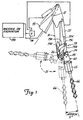
- the auger can then be placed into a storage position folded underneath the arm as shown in dotted lines in Figure 1, lowered to and rested on the ground or a support and unlatched from or latched to the quick attachment bracket.
- a powered implement arm 10 such as on an excavator or backhoe is used to mount a powered auxiliary tool, as shown an auger assembly 11.
- the arm 10 is pivotally mounted to a boom arm section 13 at pivot 12 ( Figure 1).
- the boom arm 13 is pivoted to a backhoe or excavator represented at 13A.
- the arm 10 is controlled and operated from the implement mounting platform, using hydraulic actuators from a source of hydraulic fluid under pressure, and operated by valve controls 14.
- An outer end of the arm 10 as shown mounts a link assembly 18 that is used for controlling pivoting of the tool or auger assembly 11 relative to the arm 10.
- the link assembly 18 is actuated with a double acting hydraulic actuator shown at 22 and operated through valve 14.
- the actuator 22 extends and retracts an actuator rod 22A under power and controls pivotal movement of a quick attachment mounting bracket 24 that is pivotally mounted on a pin 26 to the outer end of the arm 10.
- the actuator 22, acting through link assembly 18 will control pivoting of the bracket 24 about the horizontal axis of the pin 26.
- the hydraulic actuator can be attached directly to the bracket 24 to eliminate the link assembly 18, if desired.
- the link assembly 18 as shown, has a pair of links 19A and 19B that are pivotally mounted together with a pin 19C.
- the pin 19C also is the attachment pin for the actuator rod 22A.
- the links 19A and 19B are suitably bifurcated to permit attachment on the single pin 19C.
- the link 19A is pivotally mounted to the arm 10 with the pin 19D and the outer end of link 19B is pivotally mounted to quick attachment bracket 24 with a pin 28.
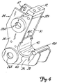
- the quick attachment bracket 24 as seen in Figures 2 and 3 and 4 has a pair of side plates 30, 30 that support a formed bar 32 that extends across the space between the side plates 30 and is welded to the side plates 30 to form an assembly.
- the side plates 30 are formed to have lower support ears 36 that are recessed to support a "C" shaped saddle or retainer 40 that also extends across the space between the side plates 30 and is welded thereto to secure the opposite ends of the quick attachment bracket 24.
- a tongue 40C of the saddle extends between the side plates.
- the side plates 30 receive the main mounting pin 26 through bores 26A and the pin 26 extends across the space between the side plates 30.
- the linkage pin 28 also extends through bores 28A and extends across the space between the side plates 30.
- a pin 38 is supported on the outer ends of the ears 36 and is held in place partially under a lead-in lip 40A on one outer edge of the "C" shaped saddle 40.
- the pin 38 extends outwardly beyond the side plates 30 to provide support ends 38A, which are used to support the auger assembly 11 during mounting and releasing an adapter or mounting frame 20 from the quick attachment bracket 24.
- the pivot pin 28, as shown for automatic operation also mounts a frame latch 41 ( Figures 2 and 3).
- the latch 41 is a yoke shaped member that has a pair of latch arms 42 held together with a latch bar 43 at their outer ends.
- the arms 42 have hubs 44 that also have bores that pivotally mount over the pivot pin 28.
- the hubs 44 have control arms 45 extending therefrom, and the arms 45 are spring loaded with strong compression springs 46 that are retained in spring supports 47 that are fixed to the side plates 30 and bear against the arms 45.
- the end 43A of the latch 41 is rounded with a large radius for smooth engagement when latching.
- the latch 41 is thus urged by the springs 46 to rotate in counterclockwise direction as shown in Figures 2 and 3, and the latch 41 is retained from rotating beyond a desired position.
- the adapter frame 20 includes a quick attachment frame 48 which is used to couple to quick attachment bracket 24 shown in Figures 1, 2, 3, 5 and 6.
- the frame 48 is made up of side plates 50, 50 that are welded to a latch backing plate 52 that is mounted to a plate 49 to make a plate assembly 55.
- the side plates 50 have hook ends 54 with receptacles 56 formed in them.
- the side plates 50 of the frame 48 are spaced wider than the side plates 30, the bar 32 and the "C" shaped saddle 40 of bracket 24. The side plates 50 thus will fit over the outside of the quick attachment bracket 24 when the bracket 24 seats in the quick attachment frame 48.
- the latch 41 is held in its "ready” position shown in Figure 2 when the quick attach bracket 24 is ready to be used in any selected way, and as shown in Figures 2 and 3, a pivoting pawl 58 is mounted on a shaft 57, on at least one side of the latch.
- the pivoting pawl 58 aligns with a hub 44 of the frame latch 41 and as shown in Figure 3 the pawl 58 is positioned to engage a stop lug 59 integral with a hub 44.
- the stop lug has a stop surface 59A for holding the latch retracted when the frame is to be released.
- Block or actuator 84 and a surface of arm 45 are used to hold the latch in the ready position as shown in Figure 2.
- the pawl 58 is spring loaded with a torsion spring 58A to rotate in clockwise direction as shown in Figure 3.
- the torsion spring 58A is shown only schematically.
- the pawl 58 is optional, in that the latch 41 can be held by actuator 84, which will be explained subsequently.
- the end of the latch 41 protrudes into the area overlying the "C" shaped saddle 40 when the latch is in its ready position as shown in Figure 2.
- the plate 52 of frame 48 in the form shown, is formed to mate with and be retained by the quick attachment bracket 24 and is perhaps best understood from the showing in Figures 2 and 3 includes a planar flange portion 52A at one end. In the mid portions of the plate 52 it bends inwardly through an opening 49A in a plate 49 that forms part of an auger mounting adapter 20 to a secure mounting plate for spaced supports 51 that mount a pivot hub 53 (See Figures 2, 3, 5 and 6). An inclined latch wall section 52B of plate 52 is formed to extend back outwardly through opening 49A.
- the plate 52 has a section 52F that is coplanar with planar flange portion 52A and the end of the plate 52 then has a flange 52C formed at an angle, as shown at right angles, to the plane of the planar flange portion 52A and the wall section 52F.
- the flange 52C has a rounded corner and is made to seat in the receptacle formed in the ears 54 of the side plates 50 of the quick attachment frame 48.
- the plate 49 is formed with an inverted channel edge portion 49B, as perhaps can be seen by referring to Figure 3.
- the channel 49B is formed with a base wall 49C and a flange 49D is formed to extend back toward the opposite end of the plate 49.
- the opening 49A formed in the plate 49 permits the latch section 52B of plate 52 to extend to position to be engaged by latch 41 when the frame 48 is attached to the mounting bracket 24.
- the frame 48 can also be retained in position with bolts that extend from the frame 48 to the bracket 24 to hold the frame 48 in place.
- the adapter frame 20 further includes a pivot frame or hanger bracket 60 that as shown has a pair of side plates 60A and 60B that are spaced apart at one end and have pivot hubs 60C therein, which fit to the outside of the hub 53, and a pivot pin 61 is used for pivotally mounting the pivot frame 60 to the attachment frame section 48. Additionally, the side plates 60A and 60B taper together at the lower end. The side plates are held with a pair of suitable spaced brace plates 60D. The lower ends of plates 60A and 60B mount a sleeve 62 which is positioned with its axis at 90° to the axis of the pivot pin 61.
- the sleeve 62 in turn carries a pivot pin 63 which passes through support ears 64 on a hydraulic motor or power unit frame assembly 65 that mounts a motor or power unit 65A shown schematically and forming the drive for the earth auger or for other tools.
- the motor frame assembly 65 mounts a hydraulic motor 65A that has an output shaft that directly drives a helical auger 66, that is used for drilling into the ground.
- the motor 65A is a power unit and can be used for powering other accessories such as a compactor plate or the like. Also, the motor can be mounted directly to the pivot frame 60, between side plates 60A and 60B.
- the side plates 60A and 60B are formed relative to the surface of latch backing plate 52 that is adjacent to the plates 60A and 60B so that the pivot frame 60 can swing relative to the attachment bracket 48 for alignment purposes when initially working, but can be also controlled by an operator actuating the actuator 22.
- the end edges of each of the plates 60A and 60B adjacent the side that is near the latch backing plate 52 have a trimmed surface 67 that is formed to be at a selected angle relative to the plane of the bent out portion 52H of backing plate 52 so it will stop against the portion 52H of backing plate 52 which is part of a plate assembly 55, when the bracket 48 is rotated counter clockwise in Figures 2 and 5 a selected amount with the attachment frame latched to quick attach bracket 24.
- FIG 2 the attachment frame 48 is shown in the progress of being attached to bracket 24.
- the edges of plates 60A and 60B on an opposite side from edge 67 are formed as shown at 68.
- the edges 67 and 68 are at angles selected so that the pivot frame 60 will be stopped on the desired position in the opposite direction of pivoting against the planar part of the plate 49, which is part of a plate assembly 55 with plate 52.
- the stop action is against either plate of the plate assembly, which can be considered a single plate for this purpose. If the latch portion 52H is not used, edge 67 can be stopped on part of plate 49.
- the portion of the side plates 60A and 60B between the edges 67 and 68 is trimmed away so that the auger pivot frame can pivot on the pin 53 a selected number of degrees in either direction of pivoting.
- the pivoting in counter clockwise direction relative to the quick attach frame with the bracket 24 positioned as shown will be about 110°, and when the actuator 22 is fully retracted, the axis of the auger will be approximately 5° from vertical in a counter clockwise direction.
- the actuator 22 is fully extended, to move the auger assembly to position also shown in dotted lines in Figure 1, but it also shows that the auger or other tool then can be above a horizontal plane.
- the auger or tool In the working position, in between the extremes, the auger or tool will float or be free to pivot about the pivot frame mounting axis and will seek a vertical position, as a pendulum. The pivoting can continue until one of the stop edges 67 and 68 engage the aligned stop formed by the plates 49 and 52.
- the auger can pivot from side to side about the axis of the pin 63, as permitted by a stop bracket 64A mounted on one of the ears 64.
- the stop bracket has ears 64B that will engage an end of a pin 60E held in brace plates 60D to limit the pivoting of the auger.
- the stops formed by the quick attach frame plate section 52A cooperating with the pivot bracket 60 permit the operator to control positioning of the auger while permitting the auger to be aligned under gravity.
- the quick attachment frame 48 can easily be installed on the quick attachment bracket 24 on the arm 10 using a procedure shown schematically in Figures 2 and 3.
- the receptacles 56 of side plates 50 are hooked onto the ends 38A of the rod 38, with the auger in an appropriate stored position.
- the auger or tool can be stored either to be in a substantially horizontal position, or supported in a vertical rack. Moving the arm 10 to the desired location and extending the actuator 22 will roll the quick attachment bracket 24 so that the nose bar 32 fits between the side plates 50, 50 and edges 32A can be rested against the plate portion 52A, both of which positions are shown in Figure 2.
- the flange 52C and the channel member 49B can then be slipped into the "C" shaped saddle 40 receptacle by moving the arm 10 about pivot 12.
- the side plates 50 have ears 70 that protrude from the plate 52, and are spaced apart. These ears 70 have slots that receive a cross retainer bar 72, that is thus spaced from the parallel plate portion 52A to form a receiver slot 73 for the nose bar 32.
- the nose bar 32 Upon sliding the quick attachment bracket 24 into position, the nose bar 32 will pass between the bar 72 and the plate portion 52A as the channel section and flange 52C seat in the receptacle on the quick attachment bracket.
- the latch 41, and in particular the nose portions 42 and the cross member 43 will slide out of the way as the quick attachment frame 48 is pushed into position.
- the latch 41 will spring back to cause the end 43A to rest against the inclined latch section 52B of plate 52 and hold the quick attachment frame 48 securely on the quick attachment bracket 24, to latch the entire auger adapter 20 in place.
- the nose bar 32 can be attached to a cross member supported on ears 70 with bolts if the automatic latch is not used.
- the latch 41 can be released for disconnecting frame 48 by actuating suitable actuators 84 that are mounted on brackets 86 on the side plates 30.
- the actuators 84 have rods 85 that act on the arms 45 and retract the latch 41 to clear the plate 52 and permit the quick attachment frame 48 to be released from the quick attachment bracket 24.
- Stop dog 58 will seat on the surface 59A to hold the latch 41 in its released position after the quick attachment frame 48 has been removed.
- the latch dog 58 is spring loaded with a torsion spring toward the surface 59A.
- a pry bar or lever can be used in recess 80 for unlatching the latch 44, for manual operation.
- the earth auger 11 or other tool thus can be quickly attached to a backhoe or excavator arm, and can be provided with the freedom about one axis to swing relative to the adapter bracket that has stop surfaces for limiting the amount of swing but permitting sufficient swing for operation.
- the hydraulic motor 65A supported on frame assembly 65 for the auger is powered in the normal manner from the power unit for the backhoe or excavator.
- Other tools can be attached to the motor and will have the freedom to pivot about the axis of pivot pin 61 until it strikes the stop edges.
Landscapes
- Engineering & Computer Science (AREA)
- Mechanical Engineering (AREA)
- Mining & Mineral Resources (AREA)
- Civil Engineering (AREA)
- General Engineering & Computer Science (AREA)
- Structural Engineering (AREA)
- Earth Drilling (AREA)
- Workshop Equipment, Work Benches, Supports, Or Storage Means (AREA)
Applications Claiming Priority (2)
| Application Number | Priority Date | Filing Date | Title |
|---|---|---|---|
| US09/028,794 US6000154A (en) | 1997-03-10 | 1998-02-24 | Quick change attachment for powered auxiliary tool |
| US28794 | 1998-02-24 |
Publications (1)
| Publication Number | Publication Date |
|---|---|
| EP0937826A2 true EP0937826A2 (fr) | 1999-08-25 |
Family
ID=21845473
Family Applications (1)
| Application Number | Title | Priority Date | Filing Date |
|---|---|---|---|
| EP99102709A Withdrawn EP0937826A2 (fr) | 1998-02-24 | 1999-02-18 | Dispositif de changement rapide pour un outil auxilliaire entrainé |
Country Status (4)
| Country | Link |
|---|---|
| US (1) | US6000154A (fr) |
| EP (1) | EP0937826A2 (fr) |
| AU (1) | AU749360B2 (fr) |
| CA (1) | CA2261468C (fr) |
Cited By (2)
| Publication number | Priority date | Publication date | Assignee | Title |
|---|---|---|---|---|
| FR2790497A1 (fr) * | 1999-03-02 | 2000-09-08 | Liebherr Hydraulikbagger | Accouplement pour la suspension pendulaire d'un outil a la fleche d'une pelle mecanique ou d'un autre dispositif de manipulation |
| CN116876593A (zh) * | 2023-07-18 | 2023-10-13 | 山东铭德港城机械有限公司 | 一种挖掘机快换结构 |
Families Citing this family (31)
| Publication number | Priority date | Publication date | Assignee | Title |
|---|---|---|---|---|
| US5727342A (en) * | 1996-04-18 | 1998-03-17 | Wain-Roy, Inc. | Hydraulic latch pin assembly for coupling a tool to a construction equipment |
| US6409457B1 (en) * | 1999-10-15 | 2002-06-25 | George Korycan | Work vehicle |
| WO2001096672A1 (fr) * | 2000-06-12 | 2001-12-20 | Clark Equipment Company | Realisation d'une barre de verrouillage destinee a un bras d'echange rapide |
| US6866467B2 (en) | 2000-11-29 | 2005-03-15 | Caterpillar S.A.R.L. | Hydraulically actuated quick coupling device |
| US6539650B2 (en) | 2000-12-05 | 2003-04-01 | Clark Equipment Company | Swivel mounting for quick attachment bracket |
| US7329082B2 (en) * | 2004-09-21 | 2008-02-12 | Ultra-Tach, Llc | Electrically actuated attachment system for tractor front end loaders |
| US7524158B2 (en) * | 2005-06-21 | 2009-04-28 | Eckstein Patrick J | Adapter for mounting skid-steer loader attachments onto an excavator arm |
| WO2007068043A1 (fr) * | 2005-12-12 | 2007-06-21 | Positti, Nicole, Elizabeth | Dispositif de sécurité pour ensemble d’attelage hydraulique |
| US7984575B2 (en) | 2007-07-05 | 2011-07-26 | Caterpillar Inc. | Quick coupler assembly |
| US20090290940A1 (en) * | 2008-05-21 | 2009-11-26 | Martin Sr John Paul | Apparatus and method for using multiple tools on a single platform |
| USD630268S1 (en) * | 2009-11-25 | 2011-01-04 | John Cunningham | Remote controlled vehicle |
| US8974137B2 (en) | 2011-12-22 | 2015-03-10 | Caterpillar Inc. | Quick coupler |
| US8869437B2 (en) | 2012-05-30 | 2014-10-28 | Caterpillar Inc. | Quick coupler |
| US8684623B2 (en) | 2012-05-30 | 2014-04-01 | Caterpillar Inc. | Tool coupler having anti-release mechanism |
| US9217235B2 (en) | 2012-05-30 | 2015-12-22 | Caterpillar Inc. | Tool coupler system having multiple pressure sources |
| GB2512294B (en) * | 2013-03-22 | 2016-01-20 | Auger Torque Europ Ltd | Auger Cradle Device, Adjustable Auger Hitch Device and Methods |
| US9228314B2 (en) | 2013-05-08 | 2016-01-05 | Caterpillar Inc. | Quick coupler hydraulic control system |
| US20140360059A1 (en) * | 2013-06-05 | 2014-12-11 | Adam Garrison | Horizontal drilling attachment for excavators |
| US10119738B2 (en) | 2014-09-26 | 2018-11-06 | Waterfurnace International Inc. | Air conditioning system with vapor injection compressor |
| GB2535479A (en) * | 2015-02-17 | 2016-08-24 | Pile Breaking Systems (Uk) Ltd | Supports |
| US9957689B2 (en) * | 2015-09-28 | 2018-05-01 | Caterpillar Inc. | Tilt bucket profile and front structure |
| US10871314B2 (en) | 2016-07-08 | 2020-12-22 | Climate Master, Inc. | Heat pump and water heater |
| US9896818B1 (en) | 2016-08-17 | 2018-02-20 | Caterpillar Inc. | Tilt bucket recessed pivot design |
| US10866002B2 (en) | 2016-11-09 | 2020-12-15 | Climate Master, Inc. | Hybrid heat pump with improved dehumidification |
| US10112788B2 (en) * | 2017-01-20 | 2018-10-30 | Mid-Columbia Producers | Sweep auger apparatus |
| US10697490B2 (en) | 2018-07-24 | 2020-06-30 | Ojjo, Inc. | Threaded truss foundations and related systems, methods, and machines |
| US11592215B2 (en) | 2018-08-29 | 2023-02-28 | Waterfurnace International, Inc. | Integrated demand water heating using a capacity modulated heat pump with desuperheater |
| US11492774B2 (en) | 2019-01-04 | 2022-11-08 | Ojjo, Inc. | Systems, methods and machines for driving screw anchors |
| US11242668B2 (en) * | 2019-07-12 | 2022-02-08 | Daedong Mobility Corp. | Quick joint of front loader |
| CA3081986A1 (fr) | 2019-07-15 | 2021-01-15 | Climate Master, Inc. | Systeme de conditionnement d`air a regulation de puissance et production d`eau chaude controlee |
| US12181189B2 (en) * | 2021-11-10 | 2024-12-31 | Climate Master, Inc. | Ceiling-mountable heat pump system |
Family Cites Families (14)
| Publication number | Priority date | Publication date | Assignee | Title |
|---|---|---|---|---|
| CA1071151A (fr) * | 1976-07-05 | 1980-02-05 | Kabushiki Kaisha Komatsu Seisakusho | Appareil pour fixer des accessoires a un engin de terrassement |
| SU763531A1 (ru) * | 1977-10-25 | 1980-09-15 | Кабардино-Балкарский государственный университет | Устройство дл креплени ковша экскаватора |
| NL170447C (nl) * | 1979-06-01 | 1984-03-16 | Bofors Nederland | Inrichting voor het koppelen van een gereedschap aan een giek met behulp van een tussenstuk en een koppelstuk. |
| GB8500911D0 (en) * | 1985-01-15 | 1985-02-20 | Mason S T | Quick-change fitting |
| JPS6393934A (ja) * | 1986-10-03 | 1988-04-25 | スチユア−ト.アレキサンダ−.エセツクス | 建設機械用連結組立体 |
| SE458534B (sv) * | 1987-07-20 | 1989-04-10 | Lidkoeping Svets & Maskinprod | Anordning vid en snabbkoppling foer loesbar sammankoppling av ett arbetsredskap och en graevmaskins manoeverarm |
| US5415235A (en) * | 1990-10-12 | 1995-05-16 | Jrb Company, Inc. | Cam locking coupler system |
| US5597283A (en) * | 1991-04-09 | 1997-01-28 | Jones; Gordon | Quick coupling for heavy equipment attachment |
| CA2072342C (fr) * | 1992-06-26 | 1994-06-14 | Robert D. Jenkins | Raccord rapide pour godets d'excavatrice et assimiles |
| DE29601727U1 (de) * | 1996-02-02 | 1996-08-01 | Nagler, Jürgen, 58313 Herdecke | Werkzeugwechselvorrichtung für Hydraulikbagger |
| JP2793165B2 (ja) * | 1996-02-06 | 1998-09-03 | 甲南電機株式会社 | 油圧ショベルのアタッチメント着脱装置 |
| US5727342A (en) * | 1996-04-18 | 1998-03-17 | Wain-Roy, Inc. | Hydraulic latch pin assembly for coupling a tool to a construction equipment |
| US5974706A (en) * | 1997-03-10 | 1999-11-02 | Clark Equipment Company | Attachment construction for earthworking implement |
| US6163989A (en) * | 1997-03-10 | 2000-12-26 | Clark Equipment Company | Frame for mounting on a boom mounted quick change bracket |
-
1998
- 1998-02-24 US US09/028,794 patent/US6000154A/en not_active Expired - Lifetime
-
1999
- 1999-02-11 CA CA002261468A patent/CA2261468C/fr not_active Expired - Lifetime
- 1999-02-12 AU AU16425/99A patent/AU749360B2/en not_active Ceased
- 1999-02-18 EP EP99102709A patent/EP0937826A2/fr not_active Withdrawn
Cited By (2)
| Publication number | Priority date | Publication date | Assignee | Title |
|---|---|---|---|---|
| FR2790497A1 (fr) * | 1999-03-02 | 2000-09-08 | Liebherr Hydraulikbagger | Accouplement pour la suspension pendulaire d'un outil a la fleche d'une pelle mecanique ou d'un autre dispositif de manipulation |
| CN116876593A (zh) * | 2023-07-18 | 2023-10-13 | 山东铭德港城机械有限公司 | 一种挖掘机快换结构 |
Also Published As
| Publication number | Publication date |
|---|---|
| AU1642599A (en) | 1999-09-09 |
| CA2261468A1 (fr) | 1999-08-24 |
| CA2261468C (fr) | 2004-11-02 |
| US6000154A (en) | 1999-12-14 |
| AU749360B2 (en) | 2002-06-27 |
Similar Documents
| Publication | Publication Date | Title |
|---|---|---|
| CA2261468C (fr) | Accessoire a changement rapide pour outil mecanique auxiliaire | |
| US6163989A (en) | Frame for mounting on a boom mounted quick change bracket | |
| US6499934B1 (en) | Implement attachment bracket for skid steer loader mounting plate | |
| AU740734B2 (en) | Attachment construction for earthworking implement | |
| US5983535A (en) | Fastener secured frame for boom mounted quick change bracket | |
| GB2330570A (en) | Quick coupler for bucket excavators | |
| JP2674712B2 (ja) | 関節式の連結構造を有するクレーン型機械 | |
| CN1401038A (zh) | 挖掘机铲斗的通用连接装置 | |
| US7832127B2 (en) | Apparatus for attaching a work tool to a loader | |
| US5865492A (en) | Hydraulic grapple assembly with side rotation mechanism | |
| US6539650B2 (en) | Swivel mounting for quick attachment bracket | |
| US20070134081A1 (en) | Tool carrier attachment adapter | |
| US7396070B2 (en) | Relocatable position operator seat station for loader | |
| CA2579106A1 (fr) | Robot avec arret de fleche | |
| CN102099532B (zh) | 用于将锄耕机附件固定至运载器提升臂的锁定装置 | |
| US4370090A (en) | Boom lock | |
| US6332748B1 (en) | Rotating pawl tool latch | |
| US6401368B1 (en) | Method and apparatus for excavating a trench | |
| US11208782B2 (en) | Post driving implement | |
| US10767339B2 (en) | Multiple interface tool for a construction machine | |
| WO2001096672A1 (fr) | Realisation d'une barre de verrouillage destinee a un bras d'echange rapide | |
| CA2261452C (fr) | Cadre pour montage sur un support a remplacement rapide monte sur une fleche | |
| JP3378196B2 (ja) | 建設機械の作業具交換構造 | |
| CA2289278C (fr) | Dispositif de verrouillage rotatif a cliquet pour outils | |
| CA2308917A1 (fr) | Raccord mecanique a serrage rapide pour outil et technique de raccordement d'outil a un bras |
Legal Events
| Date | Code | Title | Description |
|---|---|---|---|
| PUAI | Public reference made under article 153(3) epc to a published international application that has entered the european phase |
Free format text: ORIGINAL CODE: 0009012 |
|
| AK | Designated contracting states |
Kind code of ref document: A2 Designated state(s): AT BE CH CY DE DK ES FI FR GB GR IE IT LI LU MC NL PT SE |
|
| AX | Request for extension of the european patent |
Free format text: AL;LT;LV;MK;RO;SI |
|
| STAA | Information on the status of an ep patent application or granted ep patent |
Free format text: STATUS: THE APPLICATION HAS BEEN WITHDRAWN |
|
| 18W | Application withdrawn |
Withdrawal date: 20021108 |