EP0937903A2 - Drosselglied für hydraulische Verstelleinrichtungen bei Kraftfahrzeugen - Google Patents
Drosselglied für hydraulische Verstelleinrichtungen bei Kraftfahrzeugen Download PDFInfo
- Publication number
- EP0937903A2 EP0937903A2 EP98123263A EP98123263A EP0937903A2 EP 0937903 A2 EP0937903 A2 EP 0937903A2 EP 98123263 A EP98123263 A EP 98123263A EP 98123263 A EP98123263 A EP 98123263A EP 0937903 A2 EP0937903 A2 EP 0937903A2
- Authority
- EP
- European Patent Office
- Prior art keywords
- stop
- disc
- throttle element
- element according
- passage
- Prior art date
- Legal status (The legal status is an assumption and is not a legal conclusion. Google has not performed a legal analysis and makes no representation as to the accuracy of the status listed.)
- Withdrawn
Links
- 239000012530 fluid Substances 0.000 claims abstract description 25
- 238000009434 installation Methods 0.000 claims description 4
- 230000001070 adhesive effect Effects 0.000 description 1
- 230000005540 biological transmission Effects 0.000 description 1
- 238000002485 combustion reaction Methods 0.000 description 1
- 230000008878 coupling Effects 0.000 description 1
- 238000010168 coupling process Methods 0.000 description 1
- 238000005859 coupling reaction Methods 0.000 description 1
- 230000007423 decrease Effects 0.000 description 1
- 230000000694 effects Effects 0.000 description 1
- 230000001771 impaired effect Effects 0.000 description 1
- 230000036316 preload Effects 0.000 description 1
- 230000010349 pulsation Effects 0.000 description 1
- 230000003068 static effect Effects 0.000 description 1
- 230000007704 transition Effects 0.000 description 1
Images

Classifications
-
- F—MECHANICAL ENGINEERING; LIGHTING; HEATING; WEAPONS; BLASTING
- F15—FLUID-PRESSURE ACTUATORS; HYDRAULICS OR PNEUMATICS IN GENERAL
- F15B—SYSTEMS ACTING BY MEANS OF FLUIDS IN GENERAL; FLUID-PRESSURE ACTUATORS, e.g. SERVOMOTORS; DETAILS OF FLUID-PRESSURE SYSTEMS, NOT OTHERWISE PROVIDED FOR
- F15B7/00—Systems in which the movement produced is definitely related to the output of a volumetric pump; Telemotors
-
- F—MECHANICAL ENGINEERING; LIGHTING; HEATING; WEAPONS; BLASTING
- F16—ENGINEERING ELEMENTS AND UNITS; GENERAL MEASURES FOR PRODUCING AND MAINTAINING EFFECTIVE FUNCTIONING OF MACHINES OR INSTALLATIONS; THERMAL INSULATION IN GENERAL
- F16D—COUPLINGS FOR TRANSMITTING ROTATION; CLUTCHES; BRAKES
- F16D25/00—Fluid-actuated clutches
- F16D25/12—Details not specific to one of the before-mentioned types
-
- F—MECHANICAL ENGINEERING; LIGHTING; HEATING; WEAPONS; BLASTING
- F16—ENGINEERING ELEMENTS AND UNITS; GENERAL MEASURES FOR PRODUCING AND MAINTAINING EFFECTIVE FUNCTIONING OF MACHINES OR INSTALLATIONS; THERMAL INSULATION IN GENERAL
- F16D—COUPLINGS FOR TRANSMITTING ROTATION; CLUTCHES; BRAKES
- F16D25/00—Fluid-actuated clutches
- F16D25/12—Details not specific to one of the before-mentioned types
- F16D25/14—Fluid pressure control
-
- F—MECHANICAL ENGINEERING; LIGHTING; HEATING; WEAPONS; BLASTING
- F16—ENGINEERING ELEMENTS AND UNITS; GENERAL MEASURES FOR PRODUCING AND MAINTAINING EFFECTIVE FUNCTIONING OF MACHINES OR INSTALLATIONS; THERMAL INSULATION IN GENERAL
- F16D—COUPLINGS FOR TRANSMITTING ROTATION; CLUTCHES; BRAKES
- F16D48/00—External control of clutches
- F16D48/02—Control by fluid pressure
-
- F—MECHANICAL ENGINEERING; LIGHTING; HEATING; WEAPONS; BLASTING
- F16—ENGINEERING ELEMENTS AND UNITS; GENERAL MEASURES FOR PRODUCING AND MAINTAINING EFFECTIVE FUNCTIONING OF MACHINES OR INSTALLATIONS; THERMAL INSULATION IN GENERAL
- F16D—COUPLINGS FOR TRANSMITTING ROTATION; CLUTCHES; BRAKES
- F16D48/00—External control of clutches
- F16D48/02—Control by fluid pressure
- F16D2048/0215—Control by fluid pressure for damping of pulsations within the fluid system
-
- F—MECHANICAL ENGINEERING; LIGHTING; HEATING; WEAPONS; BLASTING
- F16—ENGINEERING ELEMENTS AND UNITS; GENERAL MEASURES FOR PRODUCING AND MAINTAINING EFFECTIVE FUNCTIONING OF MACHINES OR INSTALLATIONS; THERMAL INSULATION IN GENERAL
- F16D—COUPLINGS FOR TRANSMITTING ROTATION; CLUTCHES; BRAKES
- F16D2300/00—Special features for couplings or clutches
- F16D2300/22—Vibration damping
Definitions
- the invention relates to a throttle element for installation in hydraulic adjustment devices in motor vehicles, in particular for soft vehicle clutches according to the preamble of claim 1.
- From DE 37 44 070 C2 is an anti-lock hydraulic brake system for To remove vehicles, consisting of a master brake cylinder, from a Pressure fluid reservoir and at least one wheel brake, which is connected via a brake line with the master brake cylinder and via a relief line with the pressure medium reservoir is connected, with a pressure modulation valve in each of the lines mentioned is used, so that pressure is applied as a function of pressure control signals or pressure relief of the wheel brakes and with a pump, which conveys from the pressure medium reservoir and via a pressure line to the Brake line is connected, being in a connection between the pump and a throttle valve is used in the master cylinder, which in the brake line piece between the master brake cylinder and the confluence of the pressure line in the Brake line is used, the throttle valve a first check valve, the to the master cylinder locks and a second check valve that to the master cylinder out opens in parallel, the second check valve providing a biasing force having.
- a proposed throttle element in the hydraulic line is less said Dampen vibrations as the maximum flow rate when pressed in limit a flow direction, and when pushing the fluid back through the diaphragm spring of the clutch also the flow rate to a certain Limit value.
- the latter is intended to prevent the transmission from being engaged to the crankshaft of the internal combustion engine torque peaks in the drive train occur, which arise from the clutch engaging too quickly and Lead to overload, whereby the engagement speed is determined experimentally Set value that is not fallen below when switching quickly.
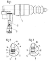
- a movement space 9 is arranged in which is a disk 4 restricted once in the flow direction of the fluid a first stop 11 and in the other flow direction against a second Stop 12 can move.
- the first stop 11 is formed by a recess between the movement space 9 and the feed line 10 to the cylinder 1.
- the second stop is formed by a stop disc 5, which is in the hydraulic line against a recess to the movement space 9 is also arranged and a passage opening 6 has.
- the disc 4 has a central bore 7 and at least on the circumference a passage channel 8 through which the fluid can flow.
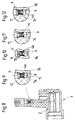
- a line is shown, which in the connection of the hydraulic line 3 is inserted.
- the line end 14 is flanged, a passage opening 15 is formed towards the center, the size of which is approximately that of Passage opening 6 of the stop plate 5 corresponds. If the line 13 against the Pushed recess of the second stop 12, the line end 14 forms the second Stop 12 for the disc 4, omitting the stop disc 5.
- a disc 4 ' is shown, which has a passage 7', but no passage channels having. Rather, passage channels 8 'are in the housing 2 as bypass lines arranged, which are guided around the first stop 11 and in the same plane end with the second stop, whereby the disc 4 'abuts the second stop 12 only the passage 7 'and at the first stop 11 the sum of all passage channels 8 'plus the passage 7' as the total cross section for the flow of the fluid be effective.
- a disc 4 '' is arranged in the movement space 9, which has a passage 7 '', which is arranged on its end face, to the second stop 12 indicates.
- Passage channels 8 ′′ are also arranged in the housing 2 and work similarly like those mentioned in Fig. 6 with the difference that they are cross-sectionally along their length are modified with the effect that the total cross section for the flow of the fluid during the movement of the disk 4 ′′ towards the first stop 11 enlarged.
- the contact surfaces of the disk 4, 4 ', 4' 'on the first stop 11 and / or to be provided on the second stop 12 with a surface which has an adhesive effect prevents, that is, the disc 4,4 ', 4' 'from the first or second Stop 11 or 12 without resistance when the flow of fluid starts from its rest position can be solved.
- the surface structure can also be on the surfaces of the first and / or second stop 11 and / or 12 may be attached, the Disc 4,4 ', 4' ', does not need to be surface treated.
- Another advantage is the inexpensive attachment of the throttle element in the form of Disk 4 in the movement space 9, this as a transition from the hydraulic line 3 can be molded in its diameter to the supply line 10 to the cylinder 1, only the second stop 12 from the stop disc 5 to be fastened is formed.
- the disk 4 acting as a valve is characterized by low costs.
- Disc 4b shown with a passage 7b connected to extensions 7B which are cylindrical and each form a step to the passage 7b.
- the disc 4b is associated with a stop disk 5 ', which forms the stop 12 and its Passage opening 6 has two chamfers to expand this passage opening.
- a throttle element which has a disc 4d with a Passage 7d, which is connected to an extension 7D, which according to one of the is directed towards both end faces of the disk 4d.
- the disc is 4d executed asymmetrically, the one end face with the passage 7d and the other end face is connected to the funnel-shaped extension 7D.
- the Stop 12 forms a stop disc 5 ′′, which is also asymmetrical and indicates with its passage opening 6 to the stop, whereas on the Stop 12 opposite plane surface connects a chamfer to the passage opening 6, which is a funnel-shaped extension.
- conical extensions can also be connected with curves, whereby the generatrices of the funnel-shaped extensions are curves that are determined empirically are and thus represent an optimum in noise generation during operation.
Landscapes
- Engineering & Computer Science (AREA)
- General Engineering & Computer Science (AREA)
- Mechanical Engineering (AREA)
- Physics & Mathematics (AREA)
- Fluid Mechanics (AREA)
- Hydraulic Clutches, Magnetic Clutches, Fluid Clutches, And Fluid Joints (AREA)
- Control Of Throttle Valves Provided In The Intake System Or In The Exhaust System (AREA)
- Actuator (AREA)
Abstract
Description
- Fig. 1
- einen Zylinder, insbesondere einen Nehmerzylinder mit einem Drosselglied in einer Hydraulikleitung;
- Fig. 2
- das Drosselglied, bestehend aus einer Scheibe in einem Bewegungsraum zwischen Hydraulikleitung und einer Zuleitung zum Zylinder in Kontakt mit einem zweiten Anschlag;
- Fig. 3
- die Scheibe im Kontakt mit einem ersten Anschlag des Bewegungsraumes;
- Fig. 4
- das Drosselglied gemäß Fig. 1 mit der Darstellung einer Leitung mit einem an der Anschlagscheibe anschlagenden Leitungsende;
- Fig. 5
- das Drosselglied gemäß Fig. 4 mit dem Leitungsende als Anschlag für die Scheibe;
- Fig. 6
- das Drosselglied mit Durchlaßkanälen entlang dem Bewegungsraum im Gehäuse;
- Fig. 7
- das Drosselglied entsprechend Fig. 6, jedoch mit einer abgewandelten Scheibe;
- Fig. 8
- einen Zylinder gemäß Fig. 1 mit einem geänderten Durchlaß in der Scheibe;
- Fig. 9
- eine Ausschnittsvergrößerung des Drosselgliedes mit zwei trichterförmigen Erweiterungen am Durchlaß;
- Fig. 10
- Ausschnittsvergrößerung des Drosselgliedes mit zwei zylindrischen Erweiterungen am Durchlaß der Scheibe;
- Fig. 11
- eine Ausschnittsvergrößerung des Drosselgliedes mit zwei konischen Erweiterungen am Durchlaß der Scheibe;
- Fig. 12
- eine Ausschnittsvergrößerung des Drosselgliedes mit einer einseitig konischen Erweiterung des Durchlasses der Scheibe.
Claims (21)
- Drosselglied zum Einbau in hydraulische Verstelleinrichtungen, insbesondere für Kraftfahrzeugkupplungen mit einem Zylinder (1), entweder einem Geberzylinder oder einem Nehmerzylinder, wobei der Geberzylinder bzw. Aktuator mit dem Nehmerzylinder durch eine mit einem Fluid gefüllte Hydraulikleitung (3) in Verbindung steht, in welcher das Drosselglied angeordnet ist, welches dem Durchfluß des Fluids in mindestens einer der beiden Durchflußrichtungen einen Drosselwiderstand entgegensetzen kann,
dadurch gekennzeichnet,daß das Drosselglied aus einem beweglichem Teil, insbesondere einer Scheibe (4,4',4'') besteht, welche mindestens einen Durchlaß (7,7',7'') und mindestens einen Durchlaßkanal (8,8',8'') aufweist, wobei sich die Scheibe (4,4',4'') bei Strömung des Fluids in den beiden Durchflußrichtungen hin- und herbewegen kann,
wobei die Scheibe (4,4',4'') einmal an einem ersten Anschlag (11) und ein anderes mal an einem zweiten Anschlag (12) anschlagen kann. - Drosselglied nach Anspruch 1,
dadurch gekennzeichnet,daß sich die Scheibe (4,4',4'') in einem Bewegungsraum (9) hin- und herbewegen kann, der in die Hydraulikleitung (3) integriert ist und im Durchmesser dieser entspricht. - Drosselglied nach Ansprüche 1 oder 2,
dadurch gekennzeichnet,daß der Bewegungsraum (9) in ein Gehäuse (2) eines Zylinders (1) im Geberzylinder oder im Nehmerzylinder integriert ist. - Drosselglied nach einem der Ansprüche 1 bis 3,
dadurch gekennzeichnet,daß der erste Anschlag (11) von einem Rezeß in der Hydraulikleitung (3) gebildet wird. - Drosselglied nach einem der Ansprüche 1 bis 4,
dadurch gekennzeichnet,daß der zweite Anschlag (12) von einer Anschlagscheibe (5) mit einer Durchtrittsöffnung (6) gebildet wird. - Drosselglied nach einem der Ansprüche 1 bis 5,
dadurch gekennzeichnet,daß der zweite Anschlag (12) vom angrenzenden Leitungsende (14) mit einer Durchtrittsöffnung (15) gebildet wird. - Drosselglied nach einem der Ansprüche 1 bis 6,
dadurch gekennzeichnet,daß bei Anlage der Scheibe (4,4',4'') am ersten Anschlag (11) ein Gesamtdurchtrittsquerschnitt gebildet wird, der sich aus der Summe der Querschnitte des Durchlassers (7,7',7'') und der Durchlaßkanäle (8,8',8'') zusammensetzt. - Drosselglied nach einem der Ansprüche 1 bis 7,
dadurch gekennzeichnet,daß die Durchlaßkanäle (8') für die Strömung des Fluids in mindestens eine Durchflußrichtung in der Scheibe (4') und/oder im Gehäuse (2) angeordnet sind. - Drosselglied nach einem der Ansprüche 1 bis 8,
dadurch gekennzeichnet,daß die Durchlaßkanäle (8') für die Strömung des Fluids in mindestens eine Durchflußrichtung in der Scheibe (4'') und/oder im Gehäuse (2) angeordnet sind. - Drosselglied nach einem der Ansprüche 1 bis 9,
dadurch gekennzeichnet,daß bei Anlage der Scheibe (4,4',4'') am zweiten Anschlag (12) ein Gesamtdurchtrittsquerschnitt gebildet wird, der lediglich aus dem Durchlaß (7,7',7'') besteht,
wobei der Durchlaß (7,7',7'') im Querschnitt gleich oder kleiner ist, als die Durchtrittsöffnung (6) und/oder die Durchtrittsöffnung (15). - Drosselglied nach einem der Ansprüche 1 bis 10,
dadurch gekennzeichnet,daß die Anlageflächen an den Anschlägen (11,12) eine bestimmte Oberflächenstruktur, insbesondere eine Rauhigkeit aufweisen. - Drosselglied nach einem der Ansprüche 1 bis 11,
dadurch gekennzeichnet,daß die Scheibe (4,4',4'') dem Fluid bei dessen Strömung vom Geberzylinder zum Nehmerzylinder einen größeren Durchtrittsquerschnitt entgegensetzt als in der umgekehrten Durchflußrichtung. - Drosselglied zum Einbau in hydraulische Verstelleinrichtungen, insbesondere für Kraftfahrzeugkupplungen mit einem Zylinder (1), entweder einem Geberzylinder oder einem Nehmerzylinder, wobei der Geberzylinder bzw. Aktuator mit dem Nehmerzylinder durch einer mit einem Fluid gefüllte Hydraulikleitung (3) in Verbindung steht, in welcher das Drosselglied angeordnet ist, welches dem Durchfluß des Fluids in mindestens einer der beiden Durchflußrichtungen einen Drosselwiderstand entgegensetzen kann,
dadurch gekennzeichnet,daß das Drosselglied aus einem beweglichen Teil, insbesondere einer Scheibe (4a,4b,4c,4d) besteht, welche mindestens einen Durchlaß (7a,7b,7c,7d) aufweist, wobei sich die Scheibe (4a,4b,4c,4d) bei Strömung des Fluids in den beiden Durchflußrichtungen innerhalb eines Bewegungsraumes (9) mit einem ersten Anschlag (11) und einem zweiten Anschlag (12) hin- und herbewegen kann, und wobei der Durchlaß (7a,7b,7c,7d) zu mindestens einem Anschlag (11,12) hin gerichtet Erweiterungen (7A,7B,7C,7D) aufweist, die Strömungsgeräusche des Fluids bei hohen Durchströmgeschwindigkeiten verhindern oder zumindest herabsetzten. - Drosselglied nach Anspruch 13,
dadurch gekennzeichnet,daß die Erweiterungen (7A,7C) zu beiden Anschlägen (11,12) hin gerichtet trichterförmig und wahlweise zueinander identisch ausgeführt sind. - Drosselglied nach Anspruch 13,
dadurch gekennzeichnet,daß die Erweiterung (7B) zu beiden Anschlägen (11,12) hin gerichtet zylindrisch und wahlweise zueinander identisch ausgeführt sind. - Drosselglied nach Anspruch 13,
dadurch gekennzeichnet,daß die Erweiterung (7D) zu einem der Anschläge (11,12) vorzugsweise zu dem Anschlag (11) hin gerichtet, konisch ausgeführt ist. - Drosselglied nach einem der Ansprüche 13 bis 16,
dadurch gekennzeichnet,daß der Anschlag (12) von einer Anschlagscheibe (5,5'5'') gebildet wird, die eine Durchtrittsöffnung (6,6',6'') aufweist. - Drosselglied nach Anspruch 17,
dadurch gekennzeichnet,daß die Durchtrittsöffnung in der Anschlagscheibe (5) als zylindrische Durchgangsbohrung angeführt ist. - Drosselglied nach Anspruch 17,
dadurch gekennzeichnet,daß die Durchtrittsöffnung in der Anschlagscheibe (5') nach beiden Seiten hin eine Fase aufweist. - Drosselglied nach Anspruch 17,
dadurch gekennzeichnet,daß die Anschlagscheibe (5'') nur zu einer Seite hin eine trichterförmige Fase aufweist. - Drosselglied nach Anspruch 20,
dadurch gekennzeichnet,daß die Fase in der Anschlagscheibe (5'') auf der dem Bewegungsraum (9) abgewandten Seite angeordnet ist.
Applications Claiming Priority (4)
| Application Number | Priority Date | Filing Date | Title |
|---|---|---|---|
| DE19807447 | 1998-02-24 | ||
| DE19807447 | 1998-02-24 | ||
| DE19850323A DE19850323A1 (de) | 1998-02-24 | 1998-11-02 | Drosselglied für hydraulische Verstelleinrichtungen bei Kraftfahrzeugen |
| DE19850323 | 1998-11-02 |
Publications (2)
| Publication Number | Publication Date |
|---|---|
| EP0937903A2 true EP0937903A2 (de) | 1999-08-25 |
| EP0937903A3 EP0937903A3 (de) | 2000-11-08 |
Family
ID=26044062
Family Applications (1)
| Application Number | Title | Priority Date | Filing Date |
|---|---|---|---|
| EP98123263A Withdrawn EP0937903A3 (de) | 1998-02-24 | 1998-12-07 | Drosselglied für hydraulische Verstelleinrichtungen bei Kraftfahrzeugen |
Country Status (2)
| Country | Link |
|---|---|
| US (1) | US6250201B1 (de) |
| EP (1) | EP0937903A3 (de) |
Cited By (3)
| Publication number | Priority date | Publication date | Assignee | Title |
|---|---|---|---|---|
| EP1793138A3 (de) * | 2005-11-30 | 2008-01-02 | LuK Lamellen und Kupplungsbau Beteiligungs KG | Drosseleinrichtung in hydraulischer Strecke zur Kupplungsbetätigung |
| US7465252B2 (en) | 2002-07-18 | 2008-12-16 | Roland Welter | Hydraulic actuation system |
| WO2011015947A1 (en) * | 2009-08-06 | 2011-02-10 | Toyota Jidosha Kabushiki Kaisha | Vehicle hydraulic clutch apparatus |
Families Citing this family (6)
| Publication number | Priority date | Publication date | Assignee | Title |
|---|---|---|---|---|
| US6546839B1 (en) * | 2000-08-22 | 2003-04-15 | Titantechnologies International, Inc. | Flow regulation device |
| US7350354B2 (en) * | 2004-05-27 | 2008-04-01 | Zf Friedrichshafen Ag | Hydraulic actuation apparatus for a motor vehicle clutch |
| US8155850B2 (en) * | 2009-07-23 | 2012-04-10 | GM Global Technology Operations LLC | System for controlling peak torque in manual transmissions |
| DE102013014205A1 (de) * | 2013-08-26 | 2015-02-26 | GM Global Technology Operations LLC (n. d. Ges. d. Staates Delaware) | Dämpfungsventil für Kupplung |
| US9708808B2 (en) * | 2015-05-21 | 2017-07-18 | Jay R. Smith Manufacturing Company | Trap primer |
| JP6478003B1 (ja) * | 2017-05-31 | 2019-03-06 | 株式会社村田製作所 | バルブおよび流体制御装置 |
Family Cites Families (24)
| Publication number | Priority date | Publication date | Assignee | Title |
|---|---|---|---|---|
| US744625A (en) * | 1900-04-07 | 1903-11-17 | Edward Sarver | Locomotive-lubricator. |
| US1435331A (en) * | 1921-10-11 | 1922-11-14 | Arthur J Pasco | Vent for automobile radiators |
| US1781366A (en) * | 1929-12-09 | 1930-11-11 | Campula Anton | Pressure-actuated valve |
| US2136898A (en) * | 1937-08-16 | 1938-11-15 | Henry H Thomas | Drain valve |
| US2353161A (en) * | 1941-12-30 | 1944-07-11 | Specialties Dev Corp | Flotation apparatus |
| US2391211A (en) * | 1945-02-23 | 1945-12-18 | Emory O White | Air operated pump for filling stations and the like |
| US2716997A (en) * | 1949-11-28 | 1955-09-06 | Exxon Research Engineering Co | Quick release timing valve |
| US2632476A (en) * | 1951-06-23 | 1953-03-24 | Dearborn Motors Corp | Hydraulic flow control device |
| US2816572A (en) * | 1955-01-17 | 1957-12-17 | Guardian Electric Mfg Co | Flow control device |
| US2886065A (en) * | 1955-08-26 | 1959-05-12 | Int Harvester Co | Variable one-way restriction valve |
| JPS5765159U (de) * | 1980-10-07 | 1982-04-19 | ||
| US4393751A (en) * | 1981-01-21 | 1983-07-19 | C. C. Kelley & Sons | Two hole hydraulic cushion valve |
| US4531543A (en) * | 1983-06-20 | 1985-07-30 | Ingersoll-Rand Company | Uni-directional flow, fluid valve |
| DE3744070C2 (de) | 1987-12-24 | 1996-02-29 | Teves Gmbh Alfred | Blockiergeschützte hydraulische Bremsanlage |
| FR2634428B1 (fr) * | 1988-07-19 | 1991-08-23 | Renault Vehicules Ind | Regulateur d'embrayage |
| US5209259A (en) * | 1991-01-15 | 1993-05-11 | E. I. Du Pont De Nemours And Company | Fluid distribution system having noise reduction mechanism |
| US5186021A (en) * | 1991-05-20 | 1993-02-16 | Carrier Corporation | Bypass expansion device having defrost optimization mode |
| DE4334551C2 (de) * | 1993-10-11 | 2002-09-26 | Luk Lamellen & Kupplungsbau | Hydraulische Betätigungseinrichtung |
| DE4338096A1 (de) * | 1993-11-08 | 1994-11-24 | Daimler Benz Ag | Vorrichtung zur Vermeidung von Überbelastungen eines Antriebstranges |
| US5655567A (en) * | 1995-06-07 | 1997-08-12 | Chrysler Corporation | Valve assembly for transmission |
| DE19730030A1 (de) * | 1996-07-16 | 1998-01-29 | Luk Lamellen & Kupplungsbau | Betätigungseinrichtung |
| DE19635612C2 (de) * | 1996-09-03 | 2002-07-18 | Zf Sachs Ag | Drossel für hydraulische Betätigungssysteme |
| DE19641233A1 (de) * | 1996-10-07 | 1998-04-09 | Mueller A & K Gmbh Co Kg | In eine Flüssigkeitsleitung oder die Aufnahmebohrung einer Armatur einsetzbarer Mengenregler |
| DE19642837C1 (de) * | 1996-10-17 | 1998-01-29 | Daimler Benz Ag | Dämpferventil |
-
1998
- 1998-12-07 EP EP98123263A patent/EP0937903A3/de not_active Withdrawn
-
1999
- 1999-02-23 US US09/255,675 patent/US6250201B1/en not_active Expired - Fee Related
Cited By (4)
| Publication number | Priority date | Publication date | Assignee | Title |
|---|---|---|---|---|
| US7465252B2 (en) | 2002-07-18 | 2008-12-16 | Roland Welter | Hydraulic actuation system |
| EP1793138A3 (de) * | 2005-11-30 | 2008-01-02 | LuK Lamellen und Kupplungsbau Beteiligungs KG | Drosseleinrichtung in hydraulischer Strecke zur Kupplungsbetätigung |
| WO2011015947A1 (en) * | 2009-08-06 | 2011-02-10 | Toyota Jidosha Kabushiki Kaisha | Vehicle hydraulic clutch apparatus |
| EP2610518A1 (de) * | 2009-08-06 | 2013-07-03 | Toyota Jidosha Kabushiki Kaisha | Hydraulische Kupplungsvorrichtung für Kfz |
Also Published As
| Publication number | Publication date |
|---|---|
| US6250201B1 (en) | 2001-06-26 |
| EP0937903A3 (de) | 2000-11-08 |
Similar Documents
| Publication | Publication Date | Title |
|---|---|---|
| EP1596085B1 (de) | Hydraulische Betätigungseinrichtung für eine Kupplung | |
| EP0157086B1 (de) | Ventilsystem für eine hydraulisch gesteuerte Anfahr-Reibungskupplung, insbesondere für Kraftfahrzeuge | |
| EP0548718B1 (de) | Kupplungsvorrichtung von Fahrzeugen | |
| DE60029877T2 (de) | Abgleichventil mit in Stufen veränderlicher Trimmung für ein selektiv in Eingriff bringbares Reibelement | |
| DE102020103774A1 (de) | Getriebe-entlüftungssystem | |
| DE19807446B4 (de) | Dämpfungsglied für hydraulische Verstelleinrichtungen bei Kraftfahrzeugen | |
| DE102005021743A1 (de) | Druckbegrenzungseinrichtung in hydraulischer Strecke zur Kupplungsbetätigung | |
| DE3525523C2 (de) | ||
| DE19850323A1 (de) | Drosselglied für hydraulische Verstelleinrichtungen bei Kraftfahrzeugen | |
| EP0462401A2 (de) | Arbeitsfahrzeug | |
| DE69204685T2 (de) | Vorrichtung zur verhinderung vom missbrauch von trockenscheibenkupplungen. | |
| DE69809809T2 (de) | Schaltgabel | |
| DE69715165T2 (de) | Bremsvorrichtung und verfahren für die anwendung bei einer sich bewegenden maschine | |
| DE2814414A1 (de) | Bremskraftregler fuer zweikreisbremsanlagen | |
| DE102015207793B4 (de) | Drosseleinheit zum Drosseln von Fluid in einer hydraulischen Strecke einer hydraulisch betätigbaren Kupplung | |
| AT8987U1 (de) | Hydrauliksystem für die steuerung zweier aktuatoren und getriebe mit einem solchen | |
| EP1077825B1 (de) | Antriebsvorrichtung | |
| EP0339328B1 (de) | Steuerventil für eine hydraulisch betätigbare Kupplung eines automatischen Kraftfahrzeuggetriebes | |
| DE4338096A1 (de) | Vorrichtung zur Vermeidung von Überbelastungen eines Antriebstranges | |
| DE19735820B4 (de) | Schaltvorrichtung eines Wechselgetriebes mit Druckregelventilen für den Arbeitsdruck und einen Versorgungsdruck | |
| DE69221377T2 (de) | Durchflussregelvorrichtung | |
| DE2707098A1 (de) | Getriebe fuer ein kraftfahrzeug | |
| DE2526885A1 (de) | Steuersystem fuer ein hydrostatisches getriebe | |
| DE19520447C1 (de) | Hydraulische Betätigungsvorrichtung mit Wegausgleich, für Reibungsbremsen mit Bremsband zum Schalten eines automatischen Getriebes von Kraftfahrzeugen | |
| DE19730030A1 (de) | Betätigungseinrichtung |
Legal Events
| Date | Code | Title | Description |
|---|---|---|---|
| PUAI | Public reference made under article 153(3) epc to a published international application that has entered the european phase |
Free format text: ORIGINAL CODE: 0009012 |
|
| AK | Designated contracting states |
Kind code of ref document: A2 Designated state(s): DE FR GB SE |
|
| AX | Request for extension of the european patent |
Free format text: AL;LT;LV;MK;RO;SI |
|
| PUAL | Search report despatched |
Free format text: ORIGINAL CODE: 0009013 |
|
| AK | Designated contracting states |
Kind code of ref document: A3 Designated state(s): AT BE CH CY DE DK ES FI FR GB GR IE IT LI LU MC NL PT SE |
|
| AX | Request for extension of the european patent |
Free format text: AL;LT;LV;MK;RO;SI |
|
| RIC1 | Information provided on ipc code assigned before grant |
Free format text: 7F 16D 25/12 A, 7B 60K 23/02 B |
|
| 17P | Request for examination filed |
Effective date: 20001228 |
|
| AKX | Designation fees paid |
Free format text: DE FR GB SE |
|
| RAP1 | Party data changed (applicant data changed or rights of an application transferred) |
Owner name: ZF SACHS AG |
|
| 17Q | First examination report despatched |
Effective date: 20030407 |
|
| STAA | Information on the status of an ep patent application or granted ep patent |
Free format text: STATUS: THE APPLICATION HAS BEEN WITHDRAWN |
|
| 18W | Application withdrawn |
Effective date: 20030718 |