EP0937929A2 - Fixiervorrichtung für Leitungen in Wandschlitzen - Google Patents
Fixiervorrichtung für Leitungen in Wandschlitzen Download PDFInfo
- Publication number
- EP0937929A2 EP0937929A2 EP99102383A EP99102383A EP0937929A2 EP 0937929 A2 EP0937929 A2 EP 0937929A2 EP 99102383 A EP99102383 A EP 99102383A EP 99102383 A EP99102383 A EP 99102383A EP 0937929 A2 EP0937929 A2 EP 0937929A2
- Authority
- EP
- European Patent Office
- Prior art keywords
- clamp
- wings
- line
- slot
- wall
- Prior art date
- Legal status (The legal status is an assumption and is not a legal conclusion. Google has not performed a legal analysis and makes no representation as to the accuracy of the status listed.)
- Granted
Links
Images


Classifications
-
- F—MECHANICAL ENGINEERING; LIGHTING; HEATING; WEAPONS; BLASTING
- F16—ENGINEERING ELEMENTS AND UNITS; GENERAL MEASURES FOR PRODUCING AND MAINTAINING EFFECTIVE FUNCTIONING OF MACHINES OR INSTALLATIONS; THERMAL INSULATION IN GENERAL
- F16L—PIPES; JOINTS OR FITTINGS FOR PIPES; SUPPORTS FOR PIPES, CABLES OR PROTECTIVE TUBING; MEANS FOR THERMAL INSULATION IN GENERAL
- F16L3/00—Supports for pipes, cables or protective tubing, e.g. hangers, holders, clamps, cleats, clips, brackets
- F16L3/02—Supports for pipes, cables or protective tubing, e.g. hangers, holders, clamps, cleats, clips, brackets partly surrounding the pipes, cables or protective tubing
- F16L3/04—Supports for pipes, cables or protective tubing, e.g. hangers, holders, clamps, cleats, clips, brackets partly surrounding the pipes, cables or protective tubing and pressing it against a wall or other support
-
- H—ELECTRICITY
- H02—GENERATION; CONVERSION OR DISTRIBUTION OF ELECTRIC POWER
- H02G—INSTALLATION OF ELECTRIC CABLES OR LINES, OR OF COMBINED OPTICAL AND ELECTRIC CABLES OR LINES
- H02G3/00—Installations of electric cables or lines or protective tubing therefor in or on buildings, equivalent structures or vehicles
- H02G3/30—Installations of cables or lines on walls, floors or ceilings
Definitions
- the invention relates to a device for the provisional fixing of lines, cables, Pipes, hoses or the like within those running in walls, ceilings or floors Slots or grooves.
- the holding device according to the invention is not only for the provisional fixing of lines, Suitable cables, pipes or hoses, but rather generally for comparable elongated installation elements, such as those used in building construction and run inside walls, ceilings, floors etc.
- the fixing device according to the invention is not for a bundle of juxtaposed Cables etc. thought. Other fastening devices are known for this for example in cable ducts.
- the fixing device according to the invention is for lines etc. thought, which can be arranged one behind the other in a wall slot can, but not next to each other.
- the object of the invention is to provide an improvement for the provisional fixing of lines, cables, pipes, hoses or the like within slots or grooves running in walls, ceilings or floors.
- the invention proposes an element which can be fastened on the line etc. and which can be clamped together with the line etc. within the slot etc.
- the basic idea of the fixing device according to the invention is based on the previous ones Tools to avoid nail and selective plastering, but instead a fixing element to be attached to the corresponding line, which is then together with the Line can be clamped in the slot or the groove.
- the big advantage is that the Lines etc. without using tools within or hammered into the walls milled grooves or slots can be fixed before they are closed again become. The pipes then become final by plastering fixed inside the wall. Through the assembly without tools according to the invention no nails, pins or screws and corresponding assembly tools required.
- the Fixing element according to the invention is simply attached to the line and completely in the Slot or wall opening pressed.
- a preferred design of the element suggests that this is essentially one C-shaped clamp, which can be plugged onto the cable etc.
- the basic idea the clamp of the invention is that it is on the line in a simple manner can be clipped on so as to ensure a stable connection between the fixing element and the line.
- the prerequisite for this is that the C-shaped clamp is flexible and partially encompasses the line with its legs, so that the encircling angle of Clamp is more than 180 °.
- a preferred development of the clamp suggests that it is in the area of the two Tavern each has outward-facing wings. These two wings are for the Clamping force responsible, which the clamp exerts within the slot and with the the clamp is held together with the line within the slot. These two Wings thus clamp the actual basic body of the C-shaped clamp inside of the slot between the adjacent slot walls. Since these wings are the Define the main holding force of the clamp, the wings must be dimensioned accordingly, to generate the necessary back pressure on the wall when clamped.
- the wings with respect to the terminal opening are directed towards the rear.
- This alignment of the wings has the advantage that the clamp with the Terminal opening - and thus the cable - pushed easily into the wall slot can be and thus with their free ends on the inner walls of the slot come to the plant.
- the length of the clamp from the front opening to the rear end of the wing should not be greater than the slot depth.
- the rearward-facing wings have the advantage that they can be compressed accordingly spread the legs of the clamp and thus the clamping of the clamp on the line is simplified.
- the wings preferably each have reinforcement at their free ends, to the necessary internal tension of the wing for the required counter pressure on the Creating wall.
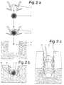
- the fixing device as such has a clamp 1 with an essentially C-shaped one Cross-sectional shape.
- the clamp body is basically a slotted cylinder jacket with a shell angle of more than 180 °, about 260 °.
- the body consists of a flexible plastic material.
- the two wings 3 protrude from the terminal opening 4 to the rear as well as obliquely outwards, so that the distance between the two free ends of the wings 3 is larger than the diameter of the terminal body. Point at their free ends the wings 3 each have reinforcements 5. The outward-facing free ends of the wings 3 run at an acute angle.
- barbs 6 are also formed on the terminal 1, which are also directed backwards and outwards. From the material thickness Here they are dimensioned smaller than the wings 3. Just like the wings 3 are the barbs 6 flexible.
- the clamp 1 or the wing 3 is located behind the barb 6 on the outside a recess 7, in which the corresponding barb 6 through Panning inward can come to a halt.
- the function of the fixing device is as follows:
- terminal 1 is open clipped on a line 8.
- To support the two wings 3 can be pressed inwards be, so that the terminal opening 4 of the leg 2 of the terminal 1 briefly expands.
- FIG. 3 is the same terminal 1 as previously described and shown.
- the only difference in the representation from FIG. 2 b is that that the slot 9 of the wall 10 has cavities 11 in which the free ends of the Barbs 6 come to rest and thus perform the function of a barb.
- terminal 1 is first on line 8 attached and then insert the unit from line 8 and terminal 1 into slot 9.
- first line 8 without the terminal 1 in the Insert slot 9 and then press clamp 1 into slot 9, the terminal 1 simultaneously clipping onto the line 8 located in the slot 9.
- the clamp 1 is correspondingly conical in the area of the clamp opening 4 beveled.
- the advantage of the fixing device according to the invention with the C-shaped clamp 1 with its Wing 3 and barb 6 is that the line 8 provisionally in a slot 9 a wall 10 can be fixed without tools, so that the slot 9 through Plastering can be completely closed again.
Landscapes
- Engineering & Computer Science (AREA)
- General Engineering & Computer Science (AREA)
- Architecture (AREA)
- Civil Engineering (AREA)
- Structural Engineering (AREA)
- Mechanical Engineering (AREA)
- Supports For Pipes And Cables (AREA)
- Installation Of Indoor Wiring (AREA)
- Details Of Indoor Wiring (AREA)
Abstract
Description
- Fig. 1 a und b
- eine Draufsicht sowie eine perspektivische Ansicht des Klemmelements;
- Fig. 2 a bis c
- der Montagevorgang des Klemmelement in einem Mauerschlitz;
- Fig. 3 a
- eine bezüglich der Darstellung in Fig. 2 b modifizierte Anordnung des Klemmelements in einer Wand, deren Innenseite des Schlitzes Aushöhlungen aufweist.
- 1
- Klemme
- 2
- Schenkel
- 3
- Flügel
- 4
- Klemmenöffnung
- 5
- Verstärkung
- 6
- Widerhaken
- 7
- Ausnehmung
- 8
- Leitung
- 9
- Schlitz
- 10
- Wand
- 11
- Aushöhlung
Claims (8)
- Vorrichtung zum provisorischen Fixieren von Leitungen (8), Kabeln, Rohren, Schläuchen oder dgl. innerhalb von in Wänden (10), Decken oder Böden verlaufenden Schlitzen (9) oder Nuten,
gekennzeichnet durch
ein auf der Leitung (8) etc. befestigbares Element, welches innerhalb des Schlitzes (9) etc. zusammen mit der Leitung (8) festklemmbar ist. - Vorrichtung nach dem vorhergehenden Anspruch,
dadurch gekennzeichnet,
daß das Element eine im wesentlichen C-förmige Klemme (1) ist, welche auf die Leitung (8) etc. aufsteckbar ist. - Vorrichtung nach Anspruch 2,
dadurch gekennzeichnet,
daß die Innenkontur der Klemme (1) im wesentlichen rund ist. - Vorrichtung nach Anspruch 2 oder 3,
dadurch gekennzeichnet,
daß die Klemme (1) im Bereich der beiden Schenkel (2) jeweils nach außen gerichtete Flügel (3) aufweist. - Vorrichtung nach Anspruch 4,
dadurch gekennzeichnet,
daß die Flügel (3) bezüglich der Klemmenöffnung (4) nach hinten gerichtet sind. - Vorrichtung nach Anspruch 4 oder 5,
dadurch gekennzeichnet,
daß die Flügel (3) an ihren freien Enden jeweils eine Verstärkung (5) aufweisen. - Vorrichtung nach einem der Ansprüche 4 bis 6,
dadurch gekennzeichnet,
daß sich in Steckrichtung gesehen vor den Flügeln (3) Widerhaken (6) befinden. - Vorrichtung nach Anspruch 7,
dadurch gekennzeichnet,
daß die Außenseite der Klemme (1) und/oder die Außenseite des jeweiligen Flügels (3) im Bereich hinter dem Widerhaken (6) eine Ausnehmung (7) aufweist.
Applications Claiming Priority (2)
| Application Number | Priority Date | Filing Date | Title |
|---|---|---|---|
| DE29803142U DE29803142U1 (de) | 1998-02-21 | 1998-02-21 | Fixiervorrichtung für Leitungen in Wandschlitzen |
| DE29803142U | 1998-02-21 |
Publications (3)
| Publication Number | Publication Date |
|---|---|
| EP0937929A2 true EP0937929A2 (de) | 1999-08-25 |
| EP0937929A3 EP0937929A3 (de) | 1999-10-06 |
| EP0937929B1 EP0937929B1 (de) | 2003-05-21 |
Family
ID=8053090
Family Applications (1)
| Application Number | Title | Priority Date | Filing Date |
|---|---|---|---|
| EP99102383A Expired - Lifetime EP0937929B1 (de) | 1998-02-21 | 1999-02-08 | Fixiervorrichtung für Leitungen in Wandschlitzen |
Country Status (3)
| Country | Link |
|---|---|
| EP (1) | EP0937929B1 (de) |
| AT (1) | ATE241105T1 (de) |
| DE (2) | DE29803142U1 (de) |
Cited By (7)
| Publication number | Priority date | Publication date | Assignee | Title |
|---|---|---|---|---|
| DE20106405U1 (de) * | 2001-04-12 | 2002-08-22 | OBO Bettermann GmbH & Co. KG, 58710 Menden | Vorrichtung zur Lagesicherung von Langformteilen |
| FR2832484A1 (fr) | 2001-11-21 | 2003-05-23 | Ram Chevilles Et Fixations Soc | Attache elastique de gaine en tranchee |
| WO2005111487A1 (en) * | 2004-05-17 | 2005-11-24 | Nielsen Frank Staerke | A retainer |
| EP1498651A3 (de) * | 2003-07-17 | 2006-04-12 | Peter Brandes | Befestigungselement |
| EP1710883A1 (de) * | 2005-04-08 | 2006-10-11 | Wilhelm Meyer | Klemmfeder zur Befestigung elektrischer oder anderer Leitungen in Mauerschlitzen. |
| EP3318385A1 (de) * | 2016-11-08 | 2018-05-09 | Sven Ziegler | Vorrichtung und verfahren zum festlegen von leitungen in kanälen von werkzeugen |
| ES2909274A1 (es) * | 2020-11-04 | 2022-05-05 | Spinex Trading S L | Dispositivo modular para sujetar tuberias empotradas en instalaciones |
Families Citing this family (9)
| Publication number | Priority date | Publication date | Assignee | Title |
|---|---|---|---|---|
| BE1012327A5 (fr) * | 1998-12-08 | 2000-09-05 | Faraeff Georges | Attache-ressort pour la fixation des tubes ou cables electriques dans le fond d'une rainure realisee dans le mur, sol ou plafond. |
| DE10352084B4 (de) * | 2003-07-17 | 2005-07-21 | Peter Brandes | Befestigungselement und Verfahren zur Festlegung von Leitungen |
| DE102013020300B4 (de) | 2012-12-04 | 2018-02-01 | Christoph Fritz Meyer | Vorrichtung zur Fixierung von Stranggut in Aussparungen |
| DK178561B1 (en) * | 2015-05-13 | 2016-06-20 | Clips Group Holding Ivs | Fixing Device |
| DE102015121728A1 (de) * | 2015-12-14 | 2017-06-14 | Hagemeister GmbH & Co. KG, Ziegelwerk | Mauerwerksverband zur Energiegewinnung |
| BE1026954B1 (nl) * | 2019-01-08 | 2020-08-14 | Tim Hendrickx | Sleufklem en werkwijze waarbij zulke sleufklem wordt toegepast |
| DE102019005426B4 (de) * | 2019-08-02 | 2025-08-07 | Michael Bruns | Schlitzklemme |
| WO2025126263A1 (ja) * | 2023-12-11 | 2025-06-19 | 日本電信電話株式会社 | 固定具、及び、固定工法 |
| DE202024102890U1 (de) | 2024-06-03 | 2024-07-17 | Martin Nosiadek | Befestigungselement |
Family Cites Families (8)
| Publication number | Priority date | Publication date | Assignee | Title |
|---|---|---|---|---|
| DE1077284B (de) * | 1954-01-15 | 1960-03-10 | Karst Fa Robert | Schelle aus elastischem Kunststoff zur Befestigung elektrischer Leitungen auf Waenden |
| CH499901A (de) * | 1968-11-19 | 1970-11-30 | Elro Produkte W E Roemer & Co | Selbsthaltende Klammer |
| GB2127236B (en) * | 1982-09-01 | 1987-02-04 | Duraplug Elect Ltd | Electric cable gripping device |
| US5150865A (en) * | 1989-12-18 | 1992-09-29 | Xerox Corporation | Universal fastener |
| DE29503619U1 (de) * | 1995-03-03 | 1995-06-29 | Thal, Stephan, 48531 Nordhorn | Kabelklemmschelle |
| NL1000944C2 (nl) * | 1995-08-07 | 1997-02-11 | Albert Japenga | Klemorgaan voor het vastzetten van een langwerpig voorwerp in een sleuf. |
| DE29600810U1 (de) * | 1996-01-18 | 1996-03-28 | Gärtner, Hans-Jürgen, 02625 Bautzen | Fixierelement für Kabel oder Leitungen |
| DE29707520U1 (de) * | 1997-04-25 | 1997-07-24 | Steidl, Hermann, 69469 Weinheim | Schelle zur Befestigung von Elektrokabeln |
-
1998
- 1998-02-21 DE DE29803142U patent/DE29803142U1/de not_active Expired - Lifetime
-
1999
- 1999-02-08 AT AT99102383T patent/ATE241105T1/de not_active IP Right Cessation
- 1999-02-08 EP EP99102383A patent/EP0937929B1/de not_active Expired - Lifetime
- 1999-02-08 DE DE59905599T patent/DE59905599D1/de not_active Expired - Lifetime
Non-Patent Citations (1)
| Title |
|---|
| None |
Cited By (8)
| Publication number | Priority date | Publication date | Assignee | Title |
|---|---|---|---|---|
| DE20106405U1 (de) * | 2001-04-12 | 2002-08-22 | OBO Bettermann GmbH & Co. KG, 58710 Menden | Vorrichtung zur Lagesicherung von Langformteilen |
| FR2832484A1 (fr) | 2001-11-21 | 2003-05-23 | Ram Chevilles Et Fixations Soc | Attache elastique de gaine en tranchee |
| EP1498651A3 (de) * | 2003-07-17 | 2006-04-12 | Peter Brandes | Befestigungselement |
| WO2005111487A1 (en) * | 2004-05-17 | 2005-11-24 | Nielsen Frank Staerke | A retainer |
| EP1710883A1 (de) * | 2005-04-08 | 2006-10-11 | Wilhelm Meyer | Klemmfeder zur Befestigung elektrischer oder anderer Leitungen in Mauerschlitzen. |
| EP3318385A1 (de) * | 2016-11-08 | 2018-05-09 | Sven Ziegler | Vorrichtung und verfahren zum festlegen von leitungen in kanälen von werkzeugen |
| ES2909274A1 (es) * | 2020-11-04 | 2022-05-05 | Spinex Trading S L | Dispositivo modular para sujetar tuberias empotradas en instalaciones |
| WO2022096763A1 (es) * | 2020-11-04 | 2022-05-12 | Spinex Trading S.L. | Dispositivo modular para sujetar tuberías empotradas en instalaciones |
Also Published As
| Publication number | Publication date |
|---|---|
| DE59905599D1 (de) | 2003-06-26 |
| EP0937929B1 (de) | 2003-05-21 |
| DE29803142U1 (de) | 1998-05-14 |
| EP0937929A3 (de) | 1999-10-06 |
| ATE241105T1 (de) | 2003-06-15 |
Similar Documents
| Publication | Publication Date | Title |
|---|---|---|
| EP0937929B1 (de) | Fixiervorrichtung für Leitungen in Wandschlitzen | |
| DE2828893C2 (de) | Rohrverbinder für Kabelschutzrohre | |
| CH641253A5 (de) | Duebelschelle. | |
| EP3209891A1 (de) | Kippdübel und verfahren zur montage eines kippdübels | |
| DE3636412C2 (de) | Verbindung stirnseitig einander gegenüber angeordneter Kabelkanäle | |
| EP2824784B1 (de) | Installationsdose | |
| EP2443352A1 (de) | Profilstabverbindungssystem | |
| DE102007012189B3 (de) | Vorrichtung zur Durchführung von Kabeln | |
| EP2163799A1 (de) | Haltevorrichtung für eine Sprinklerdüse | |
| DE202006006361U1 (de) | Einbettbare Vorrichtung zum Durchführen von Leitungen durch ein Bauteil | |
| DE4422885C2 (de) | Montageelement | |
| EP0404726A2 (de) | Vorrichtung zum Verbinden von C-förmigen Schienen, insbesondere Montageschienen | |
| EP3967828A1 (de) | Befestigungssystem für verkleidungselemente | |
| DE10315837B3 (de) | Vorrichtung zum Befestigen eines Kabels an einer Fläche | |
| EP0622575A2 (de) | Halterung mit einer Rohrschelle oder dergleichen | |
| EP3647513B1 (de) | Rohrbefestigung | |
| EP1375993A1 (de) | Kupplungsmuffe für gewellt ausgebildete Rohre | |
| AT395469B (de) | Vorrichtung zur befestigung eines durchgehenden rohres | |
| DE19816225B4 (de) | Hochbelastungshalterung, insbesondere für Wellrohre | |
| DE2457499A1 (de) | Befestigungsvorrichtung fuer fassadenplatten o.dgl. | |
| DE60110705T2 (de) | System und Verfahren zur Verbindung Kanälen | |
| DE102015210565B4 (de) | Vorrichtung und verfahren zum befestigen von medienleitungen an einem träger | |
| DE102007005290B4 (de) | Revisionsvorrichtung | |
| EP3663592B1 (de) | Verbindersystem | |
| DE102007040469B3 (de) | Schellensystem zur Befestigung von Körpern |
Legal Events
| Date | Code | Title | Description |
|---|---|---|---|
| PUAI | Public reference made under article 153(3) epc to a published international application that has entered the european phase |
Free format text: ORIGINAL CODE: 0009012 |
|
| PUAL | Search report despatched |
Free format text: ORIGINAL CODE: 0009013 |
|
| AK | Designated contracting states |
Kind code of ref document: A2 Designated state(s): AT CH DE ES FR GB IT LI NL |
|
| AX | Request for extension of the european patent |
Free format text: AL;LT;LV;MK;RO;SI |
|
| AK | Designated contracting states |
Kind code of ref document: A3 Designated state(s): AT BE CH CY DE DK ES FI FR GB GR IE IT LI LU MC NL PT SE |
|
| AX | Request for extension of the european patent |
Free format text: AL;LT;LV;MK;RO;SI |
|
| 17P | Request for examination filed |
Effective date: 20000405 |
|
| AKX | Designation fees paid |
Free format text: AT CH DE ES FR GB IT LI NL |
|
| 17Q | First examination report despatched |
Effective date: 20011010 |
|
| GRAH | Despatch of communication of intention to grant a patent |
Free format text: ORIGINAL CODE: EPIDOS IGRA |
|
| GRAH | Despatch of communication of intention to grant a patent |
Free format text: ORIGINAL CODE: EPIDOS IGRA |
|
| GRAA | (expected) grant |
Free format text: ORIGINAL CODE: 0009210 |
|
| AK | Designated contracting states |
Designated state(s): AT CH DE ES FR GB IT LI NL |
|
| PG25 | Lapsed in a contracting state [announced via postgrant information from national office to epo] |
Ref country code: NL Free format text: LAPSE BECAUSE OF FAILURE TO SUBMIT A TRANSLATION OF THE DESCRIPTION OR TO PAY THE FEE WITHIN THE PRESCRIBED TIME-LIMIT Effective date: 20030521 Ref country code: IT Free format text: LAPSE BECAUSE OF FAILURE TO SUBMIT A TRANSLATION OF THE DESCRIPTION OR TO PAY THE FEE WITHIN THE PRESCRIBED TIME-LIMIT;WARNING: LAPSES OF ITALIAN PATENTS WITH EFFECTIVE DATE BEFORE 2007 MAY HAVE OCCURRED AT ANY TIME BEFORE 2007. THE CORRECT EFFECTIVE DATE MAY BE DIFFERENT FROM THE ONE RECORDED. Effective date: 20030521 Ref country code: GB Free format text: LAPSE BECAUSE OF FAILURE TO SUBMIT A TRANSLATION OF THE DESCRIPTION OR TO PAY THE FEE WITHIN THE PRESCRIBED TIME-LIMIT Effective date: 20030521 Ref country code: FR Free format text: LAPSE BECAUSE OF FAILURE TO SUBMIT A TRANSLATION OF THE DESCRIPTION OR TO PAY THE FEE WITHIN THE PRESCRIBED TIME-LIMIT Effective date: 20030521 |
|
| REG | Reference to a national code |
Ref country code: GB Ref legal event code: FG4D Free format text: NOT ENGLISH |
|
| REG | Reference to a national code |
Ref country code: CH Ref legal event code: EP |
|
| REF | Corresponds to: |
Ref document number: 59905599 Country of ref document: DE Date of ref document: 20030626 Kind code of ref document: P |
|
| REG | Reference to a national code |
Ref country code: CH Ref legal event code: NV Representative=s name: PATENTANWALTSBUERO PETSCHNER & PARTNER |
|
| PG25 | Lapsed in a contracting state [announced via postgrant information from national office to epo] |
Ref country code: ES Free format text: LAPSE BECAUSE OF FAILURE TO SUBMIT A TRANSLATION OF THE DESCRIPTION OR TO PAY THE FEE WITHIN THE PRESCRIBED TIME-LIMIT Effective date: 20030901 |
|
| NLV1 | Nl: lapsed or annulled due to failure to fulfill the requirements of art. 29p and 29m of the patents act | ||
| GBV | Gb: ep patent (uk) treated as always having been void in accordance with gb section 77(7)/1977 [no translation filed] |
Effective date: 20030521 |
|
| PG25 | Lapsed in a contracting state [announced via postgrant information from national office to epo] |
Ref country code: AT Free format text: LAPSE BECAUSE OF NON-PAYMENT OF DUE FEES Effective date: 20040208 |
|
| PG25 | Lapsed in a contracting state [announced via postgrant information from national office to epo] |
Ref country code: LI Free format text: LAPSE BECAUSE OF NON-PAYMENT OF DUE FEES Effective date: 20040229 Ref country code: CH Free format text: LAPSE BECAUSE OF NON-PAYMENT OF DUE FEES Effective date: 20040229 |
|
| PLBE | No opposition filed within time limit |
Free format text: ORIGINAL CODE: 0009261 |
|
| STAA | Information on the status of an ep patent application or granted ep patent |
Free format text: STATUS: NO OPPOSITION FILED WITHIN TIME LIMIT |
|
| 26N | No opposition filed |
Effective date: 20040224 |
|
| EN | Fr: translation not filed | ||
| REG | Reference to a national code |
Ref country code: CH Ref legal event code: PL |
|
| REG | Reference to a national code |
Ref country code: DE Ref legal event code: R082 Ref document number: 59905599 Country of ref document: DE Representative=s name: MEPAT PATENTANWAELTE, DR. MEHL-MIKUS, GOY, DR., DE |
|
| PGFP | Annual fee paid to national office [announced via postgrant information from national office to epo] |
Ref country code: DE Payment date: 20180222 Year of fee payment: 20 |
|
| REG | Reference to a national code |
Ref country code: DE Ref legal event code: R071 Ref document number: 59905599 Country of ref document: DE |