EP0937963A2 - Vorrichung zur Messung der Höhe eines Flugkörpers - Google Patents
Vorrichung zur Messung der Höhe eines Flugkörpers Download PDFInfo
- Publication number
- EP0937963A2 EP0937963A2 EP99301175A EP99301175A EP0937963A2 EP 0937963 A2 EP0937963 A2 EP 0937963A2 EP 99301175 A EP99301175 A EP 99301175A EP 99301175 A EP99301175 A EP 99301175A EP 0937963 A2 EP0937963 A2 EP 0937963A2
- Authority
- EP
- European Patent Office
- Prior art keywords
- distance
- image
- altitude
- flying object
- ground
- Prior art date
- Legal status (The legal status is an assumption and is not a legal conclusion. Google has not performed a legal analysis and makes no representation as to the accuracy of the status listed.)
- Granted
Links
Images

Classifications
-
- G—PHYSICS
- G01—MEASURING; TESTING
- G01C—MEASURING DISTANCES, LEVELS OR BEARINGS; SURVEYING; NAVIGATION; GYROSCOPIC INSTRUMENTS; PHOTOGRAMMETRY OR VIDEOGRAMMETRY
- G01C11/00—Photogrammetry or videogrammetry, e.g. stereogrammetry; Photographic surveying
- G01C11/04—Interpretation of pictures
- G01C11/06—Interpretation of pictures by comparison of two or more pictures of the same area
-
- G—PHYSICS
- G01—MEASURING; TESTING
- G01C—MEASURING DISTANCES, LEVELS OR BEARINGS; SURVEYING; NAVIGATION; GYROSCOPIC INSTRUMENTS; PHOTOGRAMMETRY OR VIDEOGRAMMETRY
- G01C5/00—Measuring height; Measuring distances transverse to line of sight; Levelling between separated points; Surveyors' levels
- G01C5/005—Measuring height; Measuring distances transverse to line of sight; Levelling between separated points; Surveyors' levels altimeters for aircraft
-
- G—PHYSICS
- G06—COMPUTING OR CALCULATING; COUNTING
- G06T—IMAGE DATA PROCESSING OR GENERATION, IN GENERAL
- G06T7/00—Image analysis
- G06T7/70—Determining position or orientation of objects or cameras
-
- H—ELECTRICITY
- H04—ELECTRIC COMMUNICATION TECHNIQUE
- H04N—PICTORIAL COMMUNICATION, e.g. TELEVISION
- H04N13/00—Stereoscopic video systems; Multi-view video systems; Details thereof
- H04N13/20—Image signal generators
- H04N13/204—Image signal generators using stereoscopic image cameras
- H04N13/239—Image signal generators using stereoscopic image cameras using two two-dimensional [2D] image sensors having a relative position equal to or related to the interocular distance
-
- G—PHYSICS
- G06—COMPUTING OR CALCULATING; COUNTING
- G06T—IMAGE DATA PROCESSING OR GENERATION, IN GENERAL
- G06T2207/00—Indexing scheme for image analysis or image enhancement
- G06T2207/10—Image acquisition modality
- G06T2207/10004—Still image; Photographic image
- G06T2207/10012—Stereo images
-
- H—ELECTRICITY
- H04—ELECTRIC COMMUNICATION TECHNIQUE
- H04N—PICTORIAL COMMUNICATION, e.g. TELEVISION
- H04N13/00—Stereoscopic video systems; Multi-view video systems; Details thereof
- H04N13/10—Processing, recording or transmission of stereoscopic or multi-view image signals
-
- H—ELECTRICITY
- H04—ELECTRIC COMMUNICATION TECHNIQUE
- H04N—PICTORIAL COMMUNICATION, e.g. TELEVISION
- H04N13/00—Stereoscopic video systems; Multi-view video systems; Details thereof
- H04N13/10—Processing, recording or transmission of stereoscopic or multi-view image signals
- H04N13/189—Recording image signals; Reproducing recorded image signals
-
- H—ELECTRICITY
- H04—ELECTRIC COMMUNICATION TECHNIQUE
- H04N—PICTORIAL COMMUNICATION, e.g. TELEVISION
- H04N13/00—Stereoscopic video systems; Multi-view video systems; Details thereof
- H04N13/20—Image signal generators
- H04N13/204—Image signal generators using stereoscopic image cameras
- H04N13/207—Image signal generators using stereoscopic image cameras using a single two-dimensional [2D] image sensor
- H04N13/221—Image signal generators using stereoscopic image cameras using a single two-dimensional [2D] image sensor using the relative movement between cameras and objects
-
- H—ELECTRICITY
- H04—ELECTRIC COMMUNICATION TECHNIQUE
- H04N—PICTORIAL COMMUNICATION, e.g. TELEVISION
- H04N13/00—Stereoscopic video systems; Multi-view video systems; Details thereof
- H04N13/20—Image signal generators
- H04N13/296—Synchronisation thereof; Control thereof
-
- H—ELECTRICITY
- H04—ELECTRIC COMMUNICATION TECHNIQUE
- H04N—PICTORIAL COMMUNICATION, e.g. TELEVISION
- H04N13/00—Stereoscopic video systems; Multi-view video systems; Details thereof
- H04N2013/0074—Stereoscopic image analysis
- H04N2013/0081—Depth or disparity estimation from stereoscopic image signals
Definitions
- the present invention relates to an apparatus for detecting an altitude of a flying object, particularly to an apparatus for detecting an altitude of an aircraft flying at a low altitude.
- the term altitude has the particular meaning of the height of the flying object above the ground and not necessarily the height above sea level.
- an altimeter When an flying object flies at a low altitude, or when it takes off or lands, an altimeter is an essential apparatus. Recently, a technique of spraying agricultural chemicals by means of an flying object such as an unmanned helicopter has become practical.
- the first way is by remote control in which an operator controls the helicopter by radio in response to visual observation.
- the second is an autonomous control in which the helicopter flies and/or lands autonomously without the guidance of an operator.
- Remote radio control demands a high degree of skill of the operator to monitor the altitude of the helicopter by eye and to land safely.
- the unmanned helicopter is autonomously controlled so that an operator is not continuously occupied by the task of guidance as with the first radio control.
- an altimeter offering high precision altitude data is indispensable.
- altimeters there are many kinds of altimeters including an altimeter in which altitude is determined by transforming the difference of atmospheric pressure into altitude, an altimeter in which an altitude is calculated from the time taken for a reflection of a laser beam, radio wave, sonic wave or the like transmitted towards the ground to be received, an altimeter in which an altitude is found based on positional information transmitted from positioning satellites such as D-GPS, an altimeter in which an altitude is obtained from acceleration.
- positioning satellites such as D-GPS
- an altimeter in which an altitude is obtained from acceleration Taking account of accuracy, a reflecting characteristic of object on ground, (the terrain over which the altimeter is to be used) the environment in which the altimeter is used (the atmospheric conditions) and other factors into consideration, the various types of altimeters have advantages and disadvantages.
- Known altimeters do not perform entirely satisfactorily in the conditions experienced by an flying object flying at low altitude.
- the present invention provides apparatus for detecting an altitude of an flying object flying at low altitude comprising a pair of stereoscopic cameras mounted on said flying object for taking a stereoscopic image of a ground surface under the flying object, a stereoscopic processing section for processing a pair of images imaged by the cameras and for calculating a distance data of the ground surface, and an altitude calculating section for creating a configuration of the ground surface based on the distance data of a plurality of measuring points on the ground surface so as to calculate an altitude of the flying object to the ground surface.
- Figure. 1 shows a construction of an apparatus for detecting an altitude mounted on a flying object such as a helicopter which flies at a low altitude.
- the apparatus comprises a pair of stereoscopic cameras 10 for taking a three-dimensional image of a scene below the flying object, an image input section 20 to implement an input process of the image taken by the cameras 10, an original image memory 25 for storing an image processed in the image input section 20 as an original image, a stereoscopic processing section 30 for producing distance distribution information (distance image) from the original image by stereo-matching, a distance image memory 35 for storing the distance image, and an altitude calculating section 40 for calculating a ground altitude from distance information of a plurality of detecting points.
- a pair of stereoscopic cameras 10 for taking a three-dimensional image of a scene below the flying object
- an image input section 20 to implement an input process of the image taken by the cameras 10
- an original image memory 25 for storing an image processed in the image input section 20 as an original image
- Each stereoscopic camera 10 comprises two CCD cameras 10a, 10b which operate synchronously with each other and whose shutter speeds are variably controlled.
- One CCD camera 10a is used as a primary camera for imaging a reference image and the other CCD camera 10b is used as a subsidiary camera for imaging a comparison image, Further, these two cameras are disposed with a specified base length and their optical axes are arranged in parallel with each other.
- the image input section 20 comprises an analogue interface having a gain control amplifier, an AID converter for converting analogue data from the CCD cameras 10a, 10b into digital image data and a high integrated FPGA (Flexible Programmable Gate Array) having miscellaneous image processing functions such as a LOG conversion table to make a logarithmic conversion with respect to bright and shadow portions of image. That is to say, in the image input section 20, after inputting image signals from the CCD cameras 10a, 10b in order by a gain adjustment, image corrections such as improving contrasts of low brightness portions by the LOG conversion are performed and then thus corrected image signals are converted into digital image data having a given brightness. After that, those image signals are sent to the original image memory 25 for storing.
- FPGA Flexible Programmable Gate Array
- the stereoscopic processing section 30 is constituted of a high integrated FPGA containing a city-block distance calculating circuit, a deviation detecting circuit and the like. With respect to two images stored in the original image memory 25, the reference image and the comparison image, the stereo matching is performed for each small region of respective two images to obtain three-dimensional image information (distance images) expressed in numbers.
- a city-block distance between a small region of the reference image and a corresponding small region of the comparison image is calculated and then in the deviation detecting circuit, it is checked whether or not these two small regions agree by evaluating minimum and maximum values of the calculated city-block distance. If this checking condition is satisfied and the city-block distance becomes minimum, the deviation amount of picture element at this moment is a distance information of the subject small region of the reference image. Thus obtained distance information is stored in the distance image memory 35.
- Detailed processes of the stereo matching are described in Japanese Patent Application Laid-open No. Toku-Kai-Hei 5-114099 filed by the applicant of the present invention.
- the altitude calculating section 40 is constituted of an RISC processor and the like.
- the RISC (Reduced Instruction Set Computer ) processor performs a recognition process at high speeds based on the distance distribution information obtained from the distance image. That is, in the altitude calculating section 40, assuming a plane or a curved surface from distance information of many points on the ground, the length of a perpendicular line ( or possibly a vertical line from the flying object to the plane or the curved surface is defined to be a ground altitude. In this embodiment, the ground surface is detected as a plane from the distance information of multiple points on the ground and the length of a perpendicular line from the flying object down to that plane is obtained as a ground altitude. In order to speed up the calculation, the processes are substantially simplified.
- a step S1100 the distance image is read and peculiar points whose values are largely apart from the value of maximum frequency are deleted from the overall distance image.
- the process at this step S100 is a preprocess for securing an uneven-data deleting filter process which will be described hereinafter at a step S400.
- this distance image having a picture size composed of 400 (laterally) x 200 (longitudinally)picture elements, for example this distance image is divided into small regions or blocks having a distance data (deviation amount of picture element),each of which is composed of 8 (lateral) x 4 (longitudinal) picture elements.
- this distance image is divided into 25 medium regions each of which is composed of 80 (lateral) x 40 (longitudinal) picture elements. Respective medium regions include 100 (10 x 10) small regions and a histogram of deviation amount is prepared for these respective medium regions. When compared with the distance data having a maximum frequency in this histogram, if the distance data exceed a specified range (+ 1 of the distance data of the maximum frequency), the deviation amount of the block is let null to delete this peculiar point.
- a plurality of sampled regions are selected in the distance image and the position of the sampled regions on the image surface is corrected to the position having no distortion of a lens.
- 357 blocks of small region composed of 8 (lateral) x 4 (longitudinal) are selected from the image, that is, laterally 21 blocks for every 16 picture elements and longitudinally 17 blocks for every 8 picture elements.
- a distance R between the position of the distance image and a point of intersection of the optical axis and the image surface is corrected according to a correction value D expressed in the following formula (1).
- D A.R 5 + B.R 3 + C.R where A, B and C are correction coefficients determined by lens manufactures or by experiments.
- a three-dimensional coordinate of respective sampled small regions in the real space is obtained from the corrected position and the distance data of each sampled region on the CCD surface.
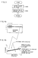
- an uneven-plane deleting filter process for deleting picture elements not constituting the plane from the distance image is performed. In this process, as shown in Figs. 4a and 4b, taking a note of a line on the image coordinate (I axis laterally, j axis vertically), a series of data is obtained on the real space coordinate (X axis laterally, Z axis longitudinally).
- this series of data is approximated to a linear equation according to the least square method, as shown in Figure. 4b.
- only data within a specified range (shown by slashes) are used for obtaining a plane and data out of the specified range are deleted. This process is repeated by scanning from top to down to delete the distance information not constituting a plane as peculiar points from the distance image.
- an altitude calculating process is performed as shown in a flowchart of Figure. 3.
Landscapes
- Engineering & Computer Science (AREA)
- Physics & Mathematics (AREA)
- General Physics & Mathematics (AREA)
- Multimedia (AREA)
- Radar, Positioning & Navigation (AREA)
- Remote Sensing (AREA)
- Signal Processing (AREA)
- Computer Vision & Pattern Recognition (AREA)
- Theoretical Computer Science (AREA)
- Image Processing (AREA)
- Measurement Of Optical Distance (AREA)
- Image Analysis (AREA)
- Length Measuring Devices By Optical Means (AREA)
Applications Claiming Priority (2)
| Application Number | Priority Date | Filing Date | Title |
|---|---|---|---|
| JP3623298 | 1998-02-18 | ||
| JP03623298A JP3850541B2 (ja) | 1998-02-18 | 1998-02-18 | 高度計測装置 |
Publications (3)
| Publication Number | Publication Date |
|---|---|
| EP0937963A2 true EP0937963A2 (de) | 1999-08-25 |
| EP0937963A3 EP0937963A3 (de) | 2002-11-20 |
| EP0937963B1 EP0937963B1 (de) | 2005-05-04 |
Family
ID=12464040
Family Applications (1)
| Application Number | Title | Priority Date | Filing Date |
|---|---|---|---|
| EP99301175A Expired - Lifetime EP0937963B1 (de) | 1998-02-18 | 1999-02-17 | Vorrichung zur Messung der Höhe eines Flugkörpers |
Country Status (4)
| Country | Link |
|---|---|
| US (1) | US6148250A (de) |
| EP (1) | EP0937963B1 (de) |
| JP (1) | JP3850541B2 (de) |
| DE (1) | DE69925057T2 (de) |
Cited By (7)
| Publication number | Priority date | Publication date | Assignee | Title |
|---|---|---|---|---|
| FR2881534A1 (fr) * | 2005-02-01 | 2006-08-04 | Airbus Sas | Procede et dispositif pour determiner la largeur d'un corridor de securite pour un aeronef, ainsi que methode et systheme de securisation d'un vol automatique a basse altitude d'un aeronef |
| EP2343501A3 (de) * | 2010-01-07 | 2014-01-08 | Korea Aerospace Research Institute | Höhenmessvorrichtung und -verfahren |
| CN108447090A (zh) * | 2016-12-09 | 2018-08-24 | 株式会社理光 | 对象姿态估计的方法、装置及电子设备 |
| EP3784983A4 (de) * | 2018-04-25 | 2022-02-09 | Bae Systems Information And Electronic Systems Integration Inc. | Passives höhenmesssystem für eine plattform und verfahren dafür |
| EP3992580A1 (de) * | 2020-11-03 | 2022-05-04 | Everdrone AB | Verfahren zur kalibrierung einer höhenmessenden stereobetrachtungsvorrichtung eines uav |
| WO2022107126A1 (en) * | 2020-11-23 | 2022-05-27 | Israel Aerospace Industries Ltd. | Location identification based on terrain model with distance measurement |
| CN115810147A (zh) * | 2021-09-14 | 2023-03-17 | 深圳荆虹科技有限公司 | 一种基于tof相机的地面检测方法、系统及移动装置 |
Families Citing this family (19)
| Publication number | Priority date | Publication date | Assignee | Title |
|---|---|---|---|---|
| US6714663B1 (en) * | 1999-11-09 | 2004-03-30 | Lockheed Martin Corp. | Method and software-implemented apparatus for ground plane estimation in multi-dimensional data |
| JP4672175B2 (ja) * | 2000-05-26 | 2011-04-20 | 本田技研工業株式会社 | 位置検出装置、位置検出方法、及び位置検出プログラム |
| JP2002228575A (ja) * | 2001-02-01 | 2002-08-14 | Asahi Eng Co Ltd | タンク鋼板の腐食診断システム |
| US6694228B2 (en) | 2002-05-09 | 2004-02-17 | Sikorsky Aircraft Corporation | Control system for remotely operated vehicles for operational payload employment |
| JP4532171B2 (ja) | 2004-06-01 | 2010-08-25 | 富士重工業株式会社 | 立体物認識装置 |
| JP4771797B2 (ja) * | 2004-11-26 | 2011-09-14 | 株式会社デンソーアイティーラボラトリ | 距離計測装置及び距離計測方法 |
| JP5113990B2 (ja) * | 2005-05-24 | 2013-01-09 | オリンパス株式会社 | 計測用内視鏡装置 |
| CN101493325B (zh) * | 2009-03-09 | 2010-11-10 | 清华大学 | 激光测绘系统 |
| US8583296B2 (en) * | 2011-05-21 | 2013-11-12 | University Of Kansas | Low-altitude altimeter and method |
| KR20130094626A (ko) * | 2012-02-16 | 2013-08-26 | 한국전자통신연구원 | 스테레오 매칭 방법 및 장치 |
| CN104574342B (zh) * | 2013-10-14 | 2017-06-23 | 株式会社理光 | 视差深度图像的噪声识别方法和噪声识别装置 |
| WO2016059930A1 (ja) | 2014-10-17 | 2016-04-21 | ソニー株式会社 | 装置、方法及びプログラム |
| CN104835164B (zh) * | 2015-05-11 | 2017-07-28 | 京东方科技集团股份有限公司 | 一种双目摄像头深度图像的处理方法及装置 |
| US9738399B2 (en) * | 2015-07-29 | 2017-08-22 | Hon Hai Precision Industry Co., Ltd. | Unmanned aerial vehicle control method and unmanned aerial vehicle using same |
| US9429953B1 (en) | 2015-08-25 | 2016-08-30 | Skycatch, Inc. | Autonomously landing an unmanned aerial vehicle |
| CN105606073A (zh) * | 2016-01-11 | 2016-05-25 | 谭圆圆 | 无人飞行器处理系统及其飞行状态数据处理方法 |
| JP6759850B2 (ja) * | 2016-08-22 | 2020-09-23 | 株式会社リコー | 情報処理システム、情報処理装置およびプログラム |
| CN116912720B (zh) * | 2023-09-12 | 2023-12-05 | 北京宝隆泓瑞科技有限公司 | 一种判断无人机影像目标是否发生重复识别的方法 |
| CN121026064A (zh) * | 2025-09-23 | 2025-11-28 | 中国电建集团贵阳勘测设计研究院有限公司 | 一种观测土石坝施工期沉降的试验装置及方法 |
Family Cites Families (11)
| Publication number | Priority date | Publication date | Assignee | Title |
|---|---|---|---|---|
| US4081214A (en) * | 1976-07-06 | 1978-03-28 | The United States Of America As Represented By The Secretary Of The Navy | Low altitude optical altimeter |
| DE2940871C2 (de) * | 1979-10-09 | 1983-11-10 | Messerschmitt-Bölkow-Blohm GmbH, 8012 Ottobrunn | Photogrammetrisches Verfahren für Fluggeräte und Raumflugkörper zur digitalen Geländedarstellung |
| JPS6288914A (ja) * | 1985-10-16 | 1987-04-23 | Nec Corp | 高度計測装置 |
| US4825393A (en) * | 1986-04-23 | 1989-04-25 | Hitachi, Ltd. | Position measuring method |
| KR930004880B1 (ko) * | 1989-03-07 | 1993-06-09 | 미쓰비시 덴끼 가부시기가이샤 | 추미식 차간거리 측정장치 |
| JPH05265547A (ja) * | 1992-03-23 | 1993-10-15 | Fuji Heavy Ind Ltd | 車輌用車外監視装置 |
| JPH05317528A (ja) * | 1992-05-22 | 1993-12-03 | Yanmar Agricult Equip Co Ltd | 防虫剤等散布用の模型航空機 |
| FR2741320B1 (fr) * | 1995-11-21 | 1998-01-02 | Sextant Avionique | Procede de pilotage a basse altitude |
| US5716032A (en) * | 1996-04-22 | 1998-02-10 | United States Of America As Represented By The Secretary Of The Army | Unmanned aerial vehicle automatic landing system |
| US5991437A (en) * | 1996-07-12 | 1999-11-23 | Real-Time Geometry Corporation | Modular digital audio system having individualized functional modules |
| JP3147002B2 (ja) * | 1996-09-26 | 2001-03-19 | 富士電機株式会社 | 距離検出値の補正方法 |
-
1998
- 1998-02-18 JP JP03623298A patent/JP3850541B2/ja not_active Expired - Fee Related
-
1999
- 1999-02-09 US US09/246,456 patent/US6148250A/en not_active Expired - Fee Related
- 1999-02-17 EP EP99301175A patent/EP0937963B1/de not_active Expired - Lifetime
- 1999-02-17 DE DE69925057T patent/DE69925057T2/de not_active Expired - Fee Related
Cited By (14)
| Publication number | Priority date | Publication date | Assignee | Title |
|---|---|---|---|---|
| FR2881534A1 (fr) * | 2005-02-01 | 2006-08-04 | Airbus Sas | Procede et dispositif pour determiner la largeur d'un corridor de securite pour un aeronef, ainsi que methode et systheme de securisation d'un vol automatique a basse altitude d'un aeronef |
| WO2006082301A1 (fr) * | 2005-02-01 | 2006-08-10 | Airbus | Procede et dispositif pour determiner la largeur d’un corridor de securite pour un aeronef, ainsi que methode et systeme de securisation d’un vol automatique a basse altitude d’un aeronef |
| CN100461059C (zh) * | 2005-02-01 | 2009-02-11 | 空中巴士公司 | 确定安全空中走廊宽度和飞机自动低空飞行的方法和系统 |
| US7949438B2 (en) | 2005-02-01 | 2011-05-24 | Airbus | Method and device for determining the width of a safety corridor for an aircraft and method and system for securing the automatic low-altitude flight of an aircraft |
| EP2343501A3 (de) * | 2010-01-07 | 2014-01-08 | Korea Aerospace Research Institute | Höhenmessvorrichtung und -verfahren |
| CN108447090B (zh) * | 2016-12-09 | 2021-12-21 | 株式会社理光 | 对象姿态估计的方法、装置及电子设备 |
| CN108447090A (zh) * | 2016-12-09 | 2018-08-24 | 株式会社理光 | 对象姿态估计的方法、装置及电子设备 |
| EP3784983A4 (de) * | 2018-04-25 | 2022-02-09 | Bae Systems Information And Electronic Systems Integration Inc. | Passives höhenmesssystem für eine plattform und verfahren dafür |
| EP3992580A1 (de) * | 2020-11-03 | 2022-05-04 | Everdrone AB | Verfahren zur kalibrierung einer höhenmessenden stereobetrachtungsvorrichtung eines uav |
| US11703355B2 (en) | 2020-11-03 | 2023-07-18 | Everdrone Ab | Method for calibrating an altitude sensing stereo vision device of a UAV |
| WO2022107126A1 (en) * | 2020-11-23 | 2022-05-27 | Israel Aerospace Industries Ltd. | Location identification based on terrain model with distance measurement |
| IL278930B1 (en) * | 2020-11-23 | 2025-04-01 | Israel Aerospace Ind Ltd | Ground model-based location identification with distance measurement |
| IL278930B2 (en) * | 2020-11-23 | 2026-05-01 | Israel Aerospace Ind Ltd | Ground model-based location identification with distance measurement |
| CN115810147A (zh) * | 2021-09-14 | 2023-03-17 | 深圳荆虹科技有限公司 | 一种基于tof相机的地面检测方法、系统及移动装置 |
Also Published As
| Publication number | Publication date |
|---|---|
| DE69925057D1 (de) | 2005-06-09 |
| DE69925057T2 (de) | 2006-03-02 |
| JPH11230745A (ja) | 1999-08-27 |
| JP3850541B2 (ja) | 2006-11-29 |
| EP0937963B1 (de) | 2005-05-04 |
| US6148250A (en) | 2000-11-14 |
| EP0937963A3 (de) | 2002-11-20 |
Similar Documents
| Publication | Publication Date | Title |
|---|---|---|
| EP0937963B1 (de) | Vorrichung zur Messung der Höhe eines Flugkörpers | |
| Glira et al. | Rigorous strip adjustment of UAV-based laserscanning data including time-dependent correction of trajectory errors | |
| Roman et al. | Application of structured light imaging for high resolution mapping of underwater archaeological sites | |
| US5606627A (en) | Automated analytic stereo comparator | |
| US8712144B2 (en) | System and method for detecting crop rows in an agricultural field | |
| KR102664900B1 (ko) | 드론을 이용한 지상기준점 측량장치 및 그 방법 | |
| US8855405B2 (en) | System and method for detecting and analyzing features in an agricultural field for vehicle guidance | |
| US8737720B2 (en) | System and method for detecting and analyzing features in an agricultural field | |
| Whitcomb et al. | Advances in underwater robot vehicles for deep ocean exploration: Navigation, control, and survey operations | |
| JP3345113B2 (ja) | 目標物認識方法及び標的同定方法 | |
| KR102262120B1 (ko) | 드론 경로 제공 방법 | |
| EP0157299B1 (de) | Bildauswertungsgerät | |
| CN113312435A (zh) | 高精度地图更新方法和设备 | |
| CN117665841B (zh) | 一种地理空间信息采集测绘方法及装置 | |
| CN110032211A (zh) | 多旋翼无人机自动避障方法 | |
| CN118172442A (zh) | 一种机载型海岸带海陆地形测绘的方法 | |
| Elbahnasawy et al. | Multi-sensor integration onboard a UAV-based mobile mapping system for agricultural management | |
| JP2004245741A (ja) | 空中写真測量方法 | |
| KR100870894B1 (ko) | 선형 스캐닝 영상의 자동 영상기하 보정 방법 | |
| KR101074277B1 (ko) | 구조물 윤곽선 추출장치 및 방법 | |
| US4669048A (en) | Computer-controlled evaluation of aerial stereo images | |
| CN119399086A (zh) | 一种轻小型无人机推扫影像扭曲变形校正方法 | |
| CN113340272A (zh) | 一种基于无人机微群的地面目标实时定位方法 | |
| Glira | Hybrid orientation of LiDAR point clouds and aerial images | |
| KR102408478B1 (ko) | 경로 추정 방법 및 이를 이용하는 장치 |
Legal Events
| Date | Code | Title | Description |
|---|---|---|---|
| PUAI | Public reference made under article 153(3) epc to a published international application that has entered the european phase |
Free format text: ORIGINAL CODE: 0009012 |
|
| AK | Designated contracting states |
Kind code of ref document: A2 Designated state(s): AT BE CH CY DE DK ES FI FR GB GR IE IT LI LU MC NL PT SE |
|
| AX | Request for extension of the european patent |
Free format text: AL;LT;LV;MK;RO;SI |
|
| PUAL | Search report despatched |
Free format text: ORIGINAL CODE: 0009013 |
|
| AK | Designated contracting states |
Kind code of ref document: A3 Designated state(s): AT BE CH CY DE DK ES FI FR GB GR IE IT LI LU MC NL PT SE |
|
| AX | Request for extension of the european patent |
Free format text: AL;LT;LV;MK;RO;SI |
|
| 17P | Request for examination filed |
Effective date: 20030514 |
|
| AKX | Designation fees paid |
Designated state(s): AT BE |
|
| RBV | Designated contracting states (corrected) |
Designated state(s): DE GB |
|
| REG | Reference to a national code |
Ref country code: DE Ref legal event code: 8566 |
|
| GRAP | Despatch of communication of intention to grant a patent |
Free format text: ORIGINAL CODE: EPIDOSNIGR1 |
|
| GRAS | Grant fee paid |
Free format text: ORIGINAL CODE: EPIDOSNIGR3 |
|
| GRAA | (expected) grant |
Free format text: ORIGINAL CODE: 0009210 |
|
| AK | Designated contracting states |
Kind code of ref document: B1 Designated state(s): DE GB |
|
| REG | Reference to a national code |
Ref country code: GB Ref legal event code: FG4D |
|
| REG | Reference to a national code |
Ref country code: IE Ref legal event code: FG4D |
|
| REF | Corresponds to: |
Ref document number: 69925057 Country of ref document: DE Date of ref document: 20050609 Kind code of ref document: P |
|
| PG25 | Lapsed in a contracting state [announced via postgrant information from national office to epo] |
Ref country code: GB Free format text: LAPSE BECAUSE OF NON-PAYMENT OF DUE FEES Effective date: 20060217 |
|
| PLBE | No opposition filed within time limit |
Free format text: ORIGINAL CODE: 0009261 |
|
| STAA | Information on the status of an ep patent application or granted ep patent |
Free format text: STATUS: NO OPPOSITION FILED WITHIN TIME LIMIT |
|
| 26N | No opposition filed |
Effective date: 20060207 |
|
| PG25 | Lapsed in a contracting state [announced via postgrant information from national office to epo] |
Ref country code: DE Free format text: LAPSE BECAUSE OF NON-PAYMENT OF DUE FEES Effective date: 20060901 |
|
| GBPC | Gb: european patent ceased through non-payment of renewal fee |
Effective date: 20060217 |