EP0937995B1 - Pressure control system for zero boiloff superconducting magnet - Google Patents
Pressure control system for zero boiloff superconducting magnet Download PDFInfo
- Publication number
- EP0937995B1 EP0937995B1 EP99301159A EP99301159A EP0937995B1 EP 0937995 B1 EP0937995 B1 EP 0937995B1 EP 99301159 A EP99301159 A EP 99301159A EP 99301159 A EP99301159 A EP 99301159A EP 0937995 B1 EP0937995 B1 EP 0937995B1
- Authority
- EP
- European Patent Office
- Prior art keywords
- pressure
- superconducting magnet
- temperature sensor
- helium
- pressure vessel
- Prior art date
- Legal status (The legal status is an assumption and is not a legal conclusion. Google has not performed a legal analysis and makes no representation as to the accuracy of the status listed.)
- Expired - Lifetime
Links
- 239000007788 liquid Substances 0.000 claims description 29
- 238000002595 magnetic resonance imaging Methods 0.000 claims description 17
- 229910052738 indium Inorganic materials 0.000 claims description 9
- APFVFJFRJDLVQX-UHFFFAOYSA-N indium atom Chemical group [In] APFVFJFRJDLVQX-UHFFFAOYSA-N 0.000 claims description 9
- 230000009471 action Effects 0.000 claims description 3
- 229910001925 ruthenium oxide Inorganic materials 0.000 claims description 2
- WOCIAKWEIIZHES-UHFFFAOYSA-N ruthenium(iv) oxide Chemical group O=[Ru]=O WOCIAKWEIIZHES-UHFFFAOYSA-N 0.000 claims description 2
- 239000001307 helium Substances 0.000 description 90
- 229910052734 helium Inorganic materials 0.000 description 90
- SWQJXJOGLNCZEY-UHFFFAOYSA-N helium atom Chemical compound [He] SWQJXJOGLNCZEY-UHFFFAOYSA-N 0.000 description 90
- 239000007789 gas Substances 0.000 description 17
- 230000005855 radiation Effects 0.000 description 6
- RYGMFSIKBFXOCR-UHFFFAOYSA-N Copper Chemical compound [Cu] RYGMFSIKBFXOCR-UHFFFAOYSA-N 0.000 description 4
- 238000009835 boiling Methods 0.000 description 4
- 238000001816 cooling Methods 0.000 description 4
- 229910052802 copper Inorganic materials 0.000 description 4
- 239000010949 copper Substances 0.000 description 4
- 238000003384 imaging method Methods 0.000 description 4
- 238000012546 transfer Methods 0.000 description 3
- 230000000712 assembly Effects 0.000 description 2
- 238000000429 assembly Methods 0.000 description 2
- 230000008878 coupling Effects 0.000 description 2
- 238000010168 coupling process Methods 0.000 description 2
- 238000005859 coupling reaction Methods 0.000 description 2
- 230000005484 gravity Effects 0.000 description 2
- 238000002955 isolation Methods 0.000 description 2
- 229920000134 Metallised film Polymers 0.000 description 1
- 230000002411 adverse Effects 0.000 description 1
- 230000008901 benefit Effects 0.000 description 1
- 238000009529 body temperature measurement Methods 0.000 description 1
- 239000000356 contaminant Substances 0.000 description 1
- 230000001276 controlling effect Effects 0.000 description 1
- 230000002596 correlated effect Effects 0.000 description 1
- 230000000875 corresponding effect Effects 0.000 description 1
- 238000009434 installation Methods 0.000 description 1
- 238000009413 insulation Methods 0.000 description 1
- 230000003993 interaction Effects 0.000 description 1
- 238000004519 manufacturing process Methods 0.000 description 1
- 239000000463 material Substances 0.000 description 1
- 238000005259 measurement Methods 0.000 description 1
- 230000010355 oscillation Effects 0.000 description 1
- 230000035515 penetration Effects 0.000 description 1
- 238000005086 pumping Methods 0.000 description 1
- 238000012827 research and development Methods 0.000 description 1
- 230000004044 response Effects 0.000 description 1
- 238000000926 separation method Methods 0.000 description 1
- 238000013517 stratification Methods 0.000 description 1
- 230000007704 transition Effects 0.000 description 1
Images

Classifications
-
- G—PHYSICS
- G01—MEASURING; TESTING
- G01R—MEASURING ELECTRIC VARIABLES; MEASURING MAGNETIC VARIABLES
- G01R33/00—Arrangements or instruments for measuring magnetic variables
- G01R33/20—Arrangements or instruments for measuring magnetic variables involving magnetic resonance
- G01R33/28—Details of apparatus provided for in groups G01R33/44 - G01R33/64
- G01R33/38—Systems for generation, homogenisation or stabilisation of the main or gradient magnetic field
- G01R33/3804—Additional hardware for cooling or heating of the magnet assembly, for housing a cooled or heated part of the magnet assembly or for temperature control of the magnet assembly
-
- F—MECHANICAL ENGINEERING; LIGHTING; HEATING; WEAPONS; BLASTING
- F25—REFRIGERATION OR COOLING; COMBINED HEATING AND REFRIGERATION SYSTEMS; HEAT PUMP SYSTEMS; MANUFACTURE OR STORAGE OF ICE; LIQUEFACTION SOLIDIFICATION OF GASES
- F25B—REFRIGERATION MACHINES, PLANTS OR SYSTEMS; COMBINED HEATING AND REFRIGERATION SYSTEMS; HEAT PUMP SYSTEMS
- F25B2400/00—General features or devices for refrigeration machines, plants or systems, combined heating and refrigeration systems or heat-pump systems, i.e. not limited to a particular subgroup of F25B
- F25B2400/17—Re-condensers
-
- G—PHYSICS
- G01—MEASURING; TESTING
- G01R—MEASURING ELECTRIC VARIABLES; MEASURING MAGNETIC VARIABLES
- G01R33/00—Arrangements or instruments for measuring magnetic variables
- G01R33/20—Arrangements or instruments for measuring magnetic variables involving magnetic resonance
- G01R33/28—Details of apparatus provided for in groups G01R33/44 - G01R33/64
- G01R33/38—Systems for generation, homogenisation or stabilisation of the main or gradient magnetic field
- G01R33/381—Systems for generation, homogenisation or stabilisation of the main or gradient magnetic field using electromagnets
- G01R33/3815—Systems for generation, homogenisation or stabilisation of the main or gradient magnetic field using electromagnets with superconducting coils, e.g. power supply therefor
-
- Y—GENERAL TAGGING OF NEW TECHNOLOGICAL DEVELOPMENTS; GENERAL TAGGING OF CROSS-SECTIONAL TECHNOLOGIES SPANNING OVER SEVERAL SECTIONS OF THE IPC; TECHNICAL SUBJECTS COVERED BY FORMER USPC CROSS-REFERENCE ART COLLECTIONS [XRACs] AND DIGESTS
- Y10—TECHNICAL SUBJECTS COVERED BY FORMER USPC
- Y10S—TECHNICAL SUBJECTS COVERED BY FORMER USPC CROSS-REFERENCE ART COLLECTIONS [XRACs] AND DIGESTS
- Y10S505/00—Superconductor technology: apparatus, material, process
- Y10S505/825—Apparatus per se, device per se, or process of making or operating same
- Y10S505/888—Refrigeration
- Y10S505/892—Magnetic device cooling
Definitions
- This invention relates to pressure control for helium cooled superconducting magnet assemblies suitable for magnetic resonance imaging (hereinafter called "MRI"), and more particularly to an improved and simplified helium bath pressure control for systems utilizing a recondenser for recondensing the resultant helium gas back into liquid helium.
- MRI magnetic resonance imaging
- a superconducting magnet can be made superconducting by placing it in an extremely cold environment, such as by enclosing it in a cryostat or pressure vessel containing a cryogen such as liquid helium.
- the extreme cold maintains current flow through the magnet coils after a power source initially connected to the coil (for a relatively short period) is disconnected due to the absence of electrical resistance in the cold magnet coils, thereby maintaining a strong magnetic field.
- Superconducting magnet assemblies find wide application in the field of MRI.
- the main superconducting magnet coils are enclosed in a cylindrically shaped pressure vessel defining an imaging bore in the central region along its axis.
- the magnetic field in the imaging bore must be very homogenous and temporally constant for accurate imaging.
- Zero boiloff magnets which recondense the helium gas back to liquid helium are often referred to as zero boiloff(ZBO) magnets.
- ZBO magnets the pressure within the helium vessel must be maintained at pressures above the exterior atmospheric pressure to prevent cryopumping.
- Cryopumping occurs when helium vessel internal pressure is less than the surrounding atmospheric pressure such that contaminants can be drawn into the helium vessel causing blockages in the magnet penetration which adversely affect MRI performance.
- Helium vessel pressure below atmospheric pressure can result if the cooling capacity of the cryogenic recondenser exceeds the heat load from the surroundings, namely the cryostat.
- a typical electrical pressure control system to avoid cryopumping requires a pressure sensor, a controller, wiring, a transducer and a control response which may be either an internal heater which is adjusted by the controller, or a cryocooler speed control system responsive to variations in pressure within the helium vessel. See, for example, U.S. Patents 4,543,794 where a temperature sensor inside the pressure vessel is used for pressure control, and 4,279,127, as well as EP 0 544 943 A.
- Pressure sensor based pressure control systems whether utilizing a single pressure sensor, or a pair of separated pressure sensors to sense pressure differentials, require an internal pressure sensor exposed to the helium gas within the helium pressure vessel requiring access to the interior of the helium vessel from the exterior pressure control system through a port or tube. This provides a passage through which unwanted heat is introduced into the helium pressure vessel through which resultant Taconis oscillations or pumping action can pump heat into the interior of the helium vessel increasing helium boiling. It is also possible for frost to form in the pressure sensor tubing affecting its operation. Moreover, pressure sensors are more expensive than other types of sensors.
- Claim 1 has been brought in the two-part form with respect to EP-A-0720024.
- a zero boiloff helium-cooled superconducting magnet utilizing a helium gas recondenser includes a pressure control system to maintain a preselected pressure within the helium pressure vessel and which is responsive to variations in pressure within the helium vessel as detected by a temperature sensor sensing corresponding variations in temperature at the recondenser positioned outside the pressure vessel to provide an accurate control signal for controlling the pressure within the helium vessel through a recondenser temperature controller.
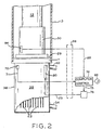
- MRI magnet system 10 includes helium pressure vessel 4 including a liquid cryogen such as helium surrounded by vacuum vessel 2 with thermally isolating radiation shield 6 interposed between the helium vessel and the vacuum vessel.
- a cryocooler 12 (which may be a Gifford-Mahon cryocooler) extends through vacuum vessel 2 within sleeve 8 such that the cold end of the cryocooler may be selectively positioned within the sleeve without destroying the vacuum within vacuum vessel 2, and heat generated by motor 9 of the cryocooler is outside the vacuum vessel.
- External cryocooler sleeve ring 14 extends outside vacuum vessel 2, and collar 19 and sleeve flange 15 enable the securing of outer cryocooler sleeve 13 to vacuum vessel 2.
- Cryocooler 12 is installed in the cryocooler sleeve assembly 8, 18, 23 with matching transition flange 21 and secured with bolts 82 and associated washers.
- First stage heat station 16 of cryocooler 12 contacts copper first stage thermal sleeve or heat sink 18 which is thermally connected through braided copper flexible thermal couplings 22 and 24 and copper thermal blocks 26 and 28 on isolating radiation shield 6 to cool the radiation shield to a temperature of approximately 60 °K providing thermal isolation between helium vessel 4 and vacuum vessel 2.
- Flexible couplings 22 and 24 also provide mechanical or vibration isolation between cryocooler 12 and radiation shield 6.
- second stage heat station 30 of cryocooler 12 contacts indium gasket 29 to efficiently provide a temperature of 4°K to heat sink 11 positioned on the opposite side of the indium gasket.
- Indium gasket 29 provides good thermal contact between the cryocooler heat station 30 and heat sink 11.
- helium recondensing chamber 38 made of high thermal conductivity material such as copper, which includes a plurality of substantially parallel heat transfer plates or surfaces 42 in thermal contact with heat sink 11 and forming passages between the surfaces of the plates for the passage of helium gas from helium pressure vessel 4.
- Helium gas 40 forms above liquid helium surface level 44 of liquid helium supply 46 through the boiling of the liquid helium in providing cryogenic temperatures to MRI magnet system 10.
- Helium gas 40 passes through gas passageway 52, through the wall 53 of helium vessel 4, and through helium gas passage 50 to the interior of the upper portion 41 of helium recondensing chamber or canister 38.
- Heat transfer plates 42 within recondenser 39 are cooled to 4° K by second stage 30 of cryocooler 12, such that helium gas 40 passing between the plates recondenses into liquid helium to collect in bottom region 48 of helium recondensing chamber 38.
- the recondensed liquid helium then flows by gravity through helium return line 54 and liquid helium passage 58 in helium vessel 4 back to liquid helium supply 46, it being noted that helium recondensing chamber 38 is positioned higher than liquid helium passageway 58 in helium vessel 4.
- liquid helium 46 cools superconducting magnet coil assembly (shown generally as 60) to a superconducting temperature with the cooling indicated generally by arrow 62 in the manner well known in the MRI art, resulting in boiling of helium liquid 46 and production of helium gas 40 above helium surface level 44.
- helium gas 40 instead of being vented to the surrounding atmosphere 37 as is common in many MRI equipments, flows through gas passageway 52 in wall 53 of helium pressure vessel 4, and through helium gas passage 50 to the interior of helium recondensing chamber 38 to pass between cryocooler cooled heat transfer plates 42 to recondense back to liquid helium.
- the recondensed liquid helium drops to bottom region 48 of the helium recondensing chamber 38 where it collects and flows by gravity through helium return line 54 and liquid helium passageway 58 through helium vessel 4 back to liquid helium supply 46, thus returning the recondensed helium gas back to the liquid helium supply as liquid helium.
- superinsulation 34 is provided in the space between radiation shield 6 and vacuum vessel 2 to further thermally isolate helium vessel 4 from vacuum vessel 2.
- Superinsulation 35 is also provided between recondensing chamber 38 and helium vessel 4 to thermally isolate the recondensing chamber 38 during servicing of cryocooler 12 which warms up cryocooler sleeve 13.
- Superinsulation 34 and 35 is aluminized Mylar multi-layer insulation used in the superconducting magnet industry.
- temperature sensor 70 which may be Ruthenium oxide cryogenic temperature sensor, such as sold by Scientific Instruments, Inc. as their Model R0600, is positioned on the surface of recondenser canister 39 proximate to second stage heat sink 11 to sense the temperature of recondenser 39.
- Output signal 71 of temperature sensor 70 is connected through connector 56 to computer control or controller 74, a Scientific Instruments model 9650 controller, to provide a control signal 75 to variable voltage source 76 within controller 74 to control current flow through electric strip heater 80 positioned on canister 38 of recondenser 39.
- Temperature sensor 70 and heater 80 are positioned in approximately diametrically opposed positions on recondensing chamber 38 to provide desirable interaction time constants.
- the spatial separation of temperature sensor 70 and heater 80 ensures that the temperature control action is stably responsive in that the temperature sensor senses the temperature of recondenser 39 and not that of the heater which when actuated would be at a temperature higher than that of the recondenser. While recondenser temperature sensor 70 is shown on recondenser canister 30 proximate or adjacent to heat station or heat sink 30, it may be placed directly on the heat station.
- temperature sensor 70 is less expensive and more readily accessible than pressure sensors connected to the interior of helium vessel 4. Moreover, the recondenser temperature sensing control is independent of differences in helium level 44 which occurs during operation of superconducting magnet 10.
- a second temperature sensor 84 may be added to take advantage of the existence and position of temperature sensor 70 to assist in the proper adjustment of cryocooler 12 relative to recondenser 39. It is important for proper cooling of recondenser 39 to have the optimum or proper pressure across indium gasket 29 to provide effective thermal contact and thermal connection to minimize thermal losses.
- the pressure or force exerted by the sandwich of the bottom of cryocooler 12 and recondenser 39 on gasket 29 is adjusted by the selective tightening of bolts 82.
- the temperature drop, if any, across indium gasket 29 can be indicated by meter 86 at controller 74.
- Temperature sensor 84 is positioned on the cryocooler side of indium gasket 29 to provide a second temperature responsive signal 88.
- bolts 82 may be selectively tightened to press cryocooler 12 against indium gasket 29 a sufficient amount to insure good thermal contact as detected by the temperature differential, if any, sensed by temperature sensors 70 and 84 and as indicated by meter 86 without overtightening and possible damaging the indium gasket.
Landscapes
- Physics & Mathematics (AREA)
- Condensed Matter Physics & Semiconductors (AREA)
- General Physics & Mathematics (AREA)
- Magnetic Resonance Imaging Apparatus (AREA)
- Containers, Films, And Cooling For Superconductive Devices (AREA)
Applications Claiming Priority (2)
| Application Number | Priority Date | Filing Date | Title |
|---|---|---|---|
| US25366 | 1979-03-30 | ||
| US09/025,366 US5936499A (en) | 1998-02-18 | 1998-02-18 | Pressure control system for zero boiloff superconducting magnet |
Publications (3)
| Publication Number | Publication Date |
|---|---|
| EP0937995A2 EP0937995A2 (en) | 1999-08-25 |
| EP0937995A3 EP0937995A3 (en) | 2000-12-06 |
| EP0937995B1 true EP0937995B1 (en) | 2006-01-18 |
Family
ID=21825614
Family Applications (1)
| Application Number | Title | Priority Date | Filing Date |
|---|---|---|---|
| EP99301159A Expired - Lifetime EP0937995B1 (en) | 1998-02-18 | 1999-02-17 | Pressure control system for zero boiloff superconducting magnet |
Country Status (4)
| Country | Link |
|---|---|
| US (1) | US5936499A (2) |
| EP (1) | EP0937995B1 (2) |
| JP (1) | JP4960539B2 (2) |
| DE (1) | DE69929494T2 (2) |
Families Citing this family (52)
| Publication number | Priority date | Publication date | Assignee | Title |
|---|---|---|---|---|
| US6560064B1 (en) * | 2000-03-21 | 2003-05-06 | International Business Machines Corporation | Disk array system with internal environmental controls |
| JP3891807B2 (ja) * | 2001-09-14 | 2007-03-14 | ジーイー・メディカル・システムズ・グローバル・テクノロジー・カンパニー・エルエルシー | 超電導マグネットの故障予測装置およびその方法、並びに磁気共鳴撮影システム |
| US6970062B2 (en) * | 2001-12-21 | 2005-11-29 | Koninklijke Philips Electronics N.V. | Cooling of a MRI system |
| DE10226498B4 (de) * | 2002-06-14 | 2004-07-29 | Bruker Biospin Gmbh | Kryostatenanordnung mit verbesserten Eigenschaften |
| US7263839B2 (en) * | 2002-10-16 | 2007-09-04 | Koninklijke Philips Electronics N.V. | Cooling device for MR apparatus |
| JP4040626B2 (ja) * | 2002-12-16 | 2008-01-30 | 住友重機械工業株式会社 | 冷凍機の取付方法及び装置 |
| US6807812B2 (en) * | 2003-03-19 | 2004-10-26 | Ge Medical Systems Global Technology Company, Llc | Pulse tube cryocooler system for magnetic resonance superconducting magnets |
| US6923009B2 (en) * | 2003-07-03 | 2005-08-02 | Ge Medical Systems Global Technology, Llc | Pre-cooler for reducing cryogen consumption |
| US6828889B1 (en) * | 2003-11-26 | 2004-12-07 | Ge Medical Systems Information Technologies, Inc. | Recondensing superconducting magnet thermal management system and method |
| US7305845B2 (en) * | 2004-03-05 | 2007-12-11 | General Electric Company | System and method for de-icing recondensor for liquid cooled zero-boil-off MR magnet |
| JP4925826B2 (ja) * | 2004-07-02 | 2012-05-09 | 株式会社日立メディコ | 磁気共鳴イメージング装置及びその保守方法 |
| US7170377B2 (en) * | 2004-07-28 | 2007-01-30 | General Electric Company | Superconductive magnet including a cryocooler coldhead |
| DE102004037173B3 (de) * | 2004-07-30 | 2005-12-15 | Bruker Biospin Ag | Vorrichtung zur kryogenverlustfreien Kühlung einer Kryostatanordnung |
| DE102005002011B3 (de) * | 2005-01-15 | 2006-04-20 | Bruker Biospin Ag | Quenchverschluß |
| US7024106B1 (en) * | 2005-01-27 | 2006-04-04 | General Electric Company | System and method for melting ice in an exhaust tube of a container holding helium |
| US7412835B2 (en) * | 2005-06-27 | 2008-08-19 | Legall Edwin L | Apparatus and method for controlling a cryocooler by adjusting cooler gas flow oscillating frequency |
| JP2007051850A (ja) * | 2005-08-19 | 2007-03-01 | Kentaro Yamaguchi | 分析用超伝導マグネット用液体ヘリウム再凝縮装置および液体ヘリウム再凝縮方法 |
| US20070068175A1 (en) * | 2005-09-28 | 2007-03-29 | Rampersad Bryce M | Control system for actively cooled cryogenic biological preservation unit |
| JP2007194258A (ja) * | 2006-01-17 | 2007-08-02 | Hitachi Ltd | 超伝導磁石装置 |
| JP4796393B2 (ja) * | 2006-01-17 | 2011-10-19 | 株式会社日立製作所 | 超電導電磁石 |
| JP4724063B2 (ja) * | 2006-07-24 | 2011-07-13 | 株式会社東芝 | 低温装置 |
| JP4908960B2 (ja) * | 2006-07-27 | 2012-04-04 | 株式会社日立製作所 | 超伝導磁石装置および磁気共鳴イメージング装置 |
| JP4855990B2 (ja) * | 2007-03-29 | 2012-01-18 | 株式会社東芝 | 再凝縮装置、その取り付け方法およびそれを用いた超電導磁石 |
| US20090301129A1 (en) * | 2008-06-08 | 2009-12-10 | Wang Nmr Inc. | Helium and nitrogen reliquefying apparatus |
| DE102008033467B4 (de) * | 2008-07-16 | 2010-04-08 | Siemens Aktiengesellschaft | Kryostat für supraleitende MR-Magnete |
| JP2012503323A (ja) * | 2008-09-22 | 2012-02-02 | コーニンクレッカ フィリップス エレクトロニクス エヌ ヴィ | 磁気共鳴システムの液体ヘリウムに対するネック除氷装置 |
| CN102054555B (zh) * | 2009-10-30 | 2014-07-16 | 通用电气公司 | 超导磁体的制冷系统、制冷方法以及核磁共振成像系统 |
| JP5539022B2 (ja) * | 2010-05-25 | 2014-07-02 | 三菱電機株式会社 | 伝導冷却超電導マグネット装置 |
| US8729894B2 (en) | 2010-07-30 | 2014-05-20 | General Electric Company | System and method for operating a magnetic resonance imaging system during ramping |
| FR2975176B1 (fr) * | 2011-05-09 | 2016-03-18 | Air Liquide | Dispositif et procede de refroidissement cryogenique |
| US10151809B2 (en) | 2011-10-21 | 2018-12-11 | Hitachi, Ltd. | Magnetic resonance imaging apparatus and operating method |
| GB2502629B (en) * | 2012-06-01 | 2015-03-11 | Siemens Plc | A closed cryogen cooling system and method for cooling a superconducting magnet |
| US9182464B2 (en) * | 2012-07-27 | 2015-11-10 | General Electric Company | Retractable current lead |
| US9700852B2 (en) * | 2012-08-28 | 2017-07-11 | So Spark Ltd. | System, method and capsules for producing sparkling drinks |
| KR101530916B1 (ko) | 2013-07-10 | 2015-06-23 | 삼성전자주식회사 | 냉동 시스템 및 이를 채용한 초전도 자석 장치 |
| US9382119B2 (en) | 2014-01-27 | 2016-07-05 | So Spark Ltd. | Rapid high-pressure microwave thermal decomposition system, capsule and method for using same |
| CN104865982B (zh) * | 2014-02-26 | 2018-04-24 | 西门子(深圳)磁共振有限公司 | 一种磁共振成像系统及其压力控制装置 |
| GB2525216B (en) * | 2014-04-16 | 2018-05-30 | Siemens Healthcare Ltd | Thermally disconnecting a Cryogenic vessel from a refrigerator |
| CN104317336B (zh) * | 2014-09-30 | 2017-01-11 | 西部超导材料科技股份有限公司 | 低温工质浸泡式超导磁体的压力控制装置的控制方法 |
| CN106033016A (zh) * | 2015-03-20 | 2016-10-19 | 西门子(深圳)磁共振有限公司 | 压力监控装置、超导磁体和磁共振成像系统 |
| JP6602716B2 (ja) * | 2016-03-30 | 2019-11-06 | ジャパンスーパーコンダクタテクノロジー株式会社 | 超電導マグネット装置 |
| JP6546115B2 (ja) * | 2016-03-30 | 2019-07-17 | ジャパンスーパーコンダクタテクノロジー株式会社 | 超電導マグネット装置 |
| GB2566024B (en) * | 2017-08-30 | 2020-08-12 | Siemens Healthcare Ltd | A Fault-Tolerant Cryogenically Cooled System |
| US11125664B2 (en) | 2017-12-04 | 2021-09-21 | Montana Instruments Corporation | Analytical instruments, methods, and components |
| US12253205B1 (en) | 2018-09-28 | 2025-03-18 | Montana Instruments Corporation | Thermal transfer line assemblies, methods of manufacturing thermal transfer line assemblies, and thermal transfer methods |
| US20200109764A1 (en) | 2018-10-09 | 2020-04-09 | Montana Instruments Corporation | Cryocooler Assemblies and Methods |
| US12181202B2 (en) | 2019-06-04 | 2024-12-31 | Montana Instruments Corporation | Thermal connection assemblies and methods |
| DE102020117235A1 (de) * | 2019-07-01 | 2021-01-07 | Montana Instruments Corporation | Kryogene Analysesysteme und Verfahren |
| JP7139303B2 (ja) * | 2019-11-01 | 2022-09-20 | ジャパンスーパーコンダクタテクノロジー株式会社 | クライオスタット用ヘリウム再凝縮装置 |
| WO2021176604A1 (ja) * | 2020-03-04 | 2021-09-10 | 三菱電機株式会社 | 超電導電磁石装置 |
| US11956924B1 (en) | 2020-08-10 | 2024-04-09 | Montana Instruments Corporation | Quantum processing circuitry cooling systems and methods |
| JP7617765B2 (ja) * | 2021-02-19 | 2025-01-20 | 住友重機械工業株式会社 | 超伝導マグネット装置 |
Family Cites Families (11)
| Publication number | Priority date | Publication date | Assignee | Title |
|---|---|---|---|---|
| US4279127A (en) * | 1979-03-02 | 1981-07-21 | Air Products And Chemicals, Inc. | Removable refrigerator for maintaining liquefied gas inventory |
| US4543794A (en) * | 1983-07-26 | 1985-10-01 | Kabushiki Kaisha Toshiba | Superconducting magnet device |
| US4484458A (en) * | 1983-11-09 | 1984-11-27 | Air Products And Chemicals, Inc. | Apparatus for condensing liquid cryogen boil-off |
| US4796433A (en) * | 1988-01-06 | 1989-01-10 | Helix Technology Corporation | Remote recondenser with intermediate temperature heat sink |
| GB2247942B (en) * | 1990-09-05 | 1994-08-03 | Mitsubishi Electric Corp | Cryostat |
| EP0544943B1 (en) * | 1991-11-27 | 1995-02-01 | Osaka Gas Co., Ltd. | Control apparatus for liquefied gas container |
| GB2292597B (en) * | 1992-03-27 | 1996-05-29 | Mitsubishi Electric Corp | Superconducting magnet and method for assembling the same |
| US5398515A (en) * | 1993-05-19 | 1995-03-21 | Rockwell International Corporation | Fluid management system for a zero gravity cryogenic storage system |
| EP0720024B1 (en) * | 1994-12-29 | 2001-11-14 | General Electric Company | Helium recondensing superconducting magnet |
| JPH09120789A (ja) * | 1995-10-25 | 1997-05-06 | Jeol Ltd | 試料冷却システム |
| US5613367A (en) * | 1995-12-28 | 1997-03-25 | General Electric Company | Cryogen recondensing superconducting magnet |
-
1998
- 1998-02-18 US US09/025,366 patent/US5936499A/en not_active Expired - Lifetime
-
1999
- 1999-02-12 JP JP03360999A patent/JP4960539B2/ja not_active Expired - Lifetime
- 1999-02-17 DE DE69929494T patent/DE69929494T2/de not_active Expired - Lifetime
- 1999-02-17 EP EP99301159A patent/EP0937995B1/en not_active Expired - Lifetime
Also Published As
| Publication number | Publication date |
|---|---|
| US5936499A (en) | 1999-08-10 |
| JPH11317307A (ja) | 1999-11-16 |
| DE69929494T2 (de) | 2006-09-14 |
| DE69929494D1 (de) | 2006-04-06 |
| EP0937995A2 (en) | 1999-08-25 |
| JP4960539B2 (ja) | 2012-06-27 |
| EP0937995A3 (en) | 2000-12-06 |
Similar Documents
| Publication | Publication Date | Title |
|---|---|---|
| EP0937995B1 (en) | Pressure control system for zero boiloff superconducting magnet | |
| EP0974849B1 (en) | Thermal conductance gasket for zero boiloff superconducting magnet | |
| US7170377B2 (en) | Superconductive magnet including a cryocooler coldhead | |
| US5613367A (en) | Cryogen recondensing superconducting magnet | |
| US5782095A (en) | Cryogen recondensing superconducting magnet | |
| US5744959A (en) | NMR measurement apparatus with pulse tube cooler | |
| EP0773565B1 (en) | Cryogen-cooled open MRI superconductive magnet | |
| US6807812B2 (en) | Pulse tube cryocooler system for magnetic resonance superconducting magnets | |
| US5410286A (en) | Quench-protected, refrigerated superconducting magnet | |
| EP0720024B1 (en) | Helium recondensing superconducting magnet | |
| US5485730A (en) | Remote cooling system for a superconducting magnet | |
| JP4031121B2 (ja) | クライオスタット装置 | |
| US20080115510A1 (en) | Cryostats including current leads for electronically powered equipment | |
| US5442928A (en) | Hybrid cooling system for a superconducting magnet | |
| WO2003044424A3 (en) | A cryogenic assembly | |
| US12292366B2 (en) | Cryogenic analysis systems and methods | |
| US5828280A (en) | Passive conductor heater for zero boiloff superconducting magnet pressure control | |
| US11393614B2 (en) | Current lead assembly for cryogenic apparatus | |
| US20150128617A1 (en) | Closed Cryogen Cooling System And Method For Cooling A Superconducting Magnet | |
| US11320500B2 (en) | Cryogenic device for magnetic resonance imagery scanner and magnetic resonance imagery assembly comprising such cryogenic device | |
| US12112887B2 (en) | Switch assemblies of superconducting magnet assemblies and reconfigurable superconducting magnet assemblies of a cryogenic system | |
| Jirmanus | Introduction to laboratory cryogenics | |
| US20250239389A1 (en) | Switch assemblies of superconducting magnet assemblies and reconfigurable superconducting magnet assemblies of a cryogenic system | |
| US20260063741A1 (en) | Cryogenic System and Magnetic Resonance Device | |
| CN118859058A (zh) | 磁共振装置 |
Legal Events
| Date | Code | Title | Description |
|---|---|---|---|
| PUAI | Public reference made under article 153(3) epc to a published international application that has entered the european phase |
Free format text: ORIGINAL CODE: 0009012 |
|
| AK | Designated contracting states |
Kind code of ref document: A2 Designated state(s): DE GB NL |
|
| AX | Request for extension of the european patent |
Free format text: AL;LT;LV;MK;RO;SI |
|
| PUAL | Search report despatched |
Free format text: ORIGINAL CODE: 0009013 |
|
| AK | Designated contracting states |
Kind code of ref document: A3 Designated state(s): AT BE CH CY DE DK ES FI FR GB GR IE IT LI LU MC NL PT SE |
|
| AX | Request for extension of the european patent |
Free format text: AL;LT;LV;MK;RO;SI |
|
| RIC1 | Information provided on ipc code assigned before grant |
Free format text: 7G 01R 33/3815 A, 7F 17C 13/02 B |
|
| 17P | Request for examination filed |
Effective date: 20010606 |
|
| AKX | Designation fees paid |
Free format text: DE GB NL |
|
| 17Q | First examination report despatched |
Effective date: 20050131 |
|
| GRAP | Despatch of communication of intention to grant a patent |
Free format text: ORIGINAL CODE: EPIDOSNIGR1 |
|
| GRAS | Grant fee paid |
Free format text: ORIGINAL CODE: EPIDOSNIGR3 |
|
| GRAA | (expected) grant |
Free format text: ORIGINAL CODE: 0009210 |
|
| AK | Designated contracting states |
Kind code of ref document: B1 Designated state(s): DE GB NL |
|
| REG | Reference to a national code |
Ref country code: GB Ref legal event code: FG4D |
|
| REF | Corresponds to: |
Ref document number: 69929494 Country of ref document: DE Date of ref document: 20060406 Kind code of ref document: P |
|
| PLBE | No opposition filed within time limit |
Free format text: ORIGINAL CODE: 0009261 |
|
| STAA | Information on the status of an ep patent application or granted ep patent |
Free format text: STATUS: NO OPPOSITION FILED WITHIN TIME LIMIT |
|
| 26N | No opposition filed |
Effective date: 20061019 |
|
| PGFP | Annual fee paid to national office [announced via postgrant information from national office to epo] |
Ref country code: NL Payment date: 20080224 Year of fee payment: 10 |
|
| NLV4 | Nl: lapsed or anulled due to non-payment of the annual fee |
Effective date: 20090901 |
|
| PG25 | Lapsed in a contracting state [announced via postgrant information from national office to epo] |
Ref country code: NL Free format text: LAPSE BECAUSE OF NON-PAYMENT OF DUE FEES Effective date: 20090901 |
|
| PGFP | Annual fee paid to national office [announced via postgrant information from national office to epo] |
Ref country code: GB Payment date: 20180227 Year of fee payment: 20 Ref country code: DE Payment date: 20180227 Year of fee payment: 20 |
|
| REG | Reference to a national code |
Ref country code: DE Ref legal event code: R071 Ref document number: 69929494 Country of ref document: DE |
|
| REG | Reference to a national code |
Ref country code: GB Ref legal event code: PE20 Expiry date: 20190216 |
|
| PG25 | Lapsed in a contracting state [announced via postgrant information from national office to epo] |
Ref country code: GB Free format text: LAPSE BECAUSE OF EXPIRATION OF PROTECTION Effective date: 20190216 |