EP0938006B1 - Strukturen für optisches Halbleitermodul, optischen Steckverbinder und formadaptiven optischen Steckverbinder - Google Patents
Strukturen für optisches Halbleitermodul, optischen Steckverbinder und formadaptiven optischen Steckverbinder Download PDFInfo
- Publication number
- EP0938006B1 EP0938006B1 EP99102763A EP99102763A EP0938006B1 EP 0938006 B1 EP0938006 B1 EP 0938006B1 EP 99102763 A EP99102763 A EP 99102763A EP 99102763 A EP99102763 A EP 99102763A EP 0938006 B1 EP0938006 B1 EP 0938006B1
- Authority
- EP
- European Patent Office
- Prior art keywords
- optical
- regulating means
- connector
- coupling
- module
- Prior art date
- Legal status (The legal status is an assumption and is not a legal conclusion. Google has not performed a legal analysis and makes no representation as to the accuracy of the status listed.)
- Expired - Lifetime
Links
Images





Classifications
-
- G—PHYSICS
- G02—OPTICS
- G02B—OPTICAL ELEMENTS, SYSTEMS OR APPARATUS
- G02B6/00—Light guides; Structural details of arrangements comprising light guides and other optical elements, e.g. couplings
- G02B6/24—Coupling light guides
- G02B6/42—Coupling light guides with opto-electronic elements
- G02B6/4201—Packages, e.g. shape, construction, internal or external details
-
- G—PHYSICS
- G02—OPTICS
- G02B—OPTICAL ELEMENTS, SYSTEMS OR APPARATUS
- G02B6/00—Light guides; Structural details of arrangements comprising light guides and other optical elements, e.g. couplings
- G02B6/24—Coupling light guides
- G02B6/42—Coupling light guides with opto-electronic elements
- G02B6/4201—Packages, e.g. shape, construction, internal or external details
- G02B6/4256—Details of housings
- G02B6/426—Details of housings mounting, engaging or coupling of the package to a board, a frame or a panel
- G02B6/4261—Packages with mounting structures to be pluggable or detachable, e.g. having latches or rails
-
- G—PHYSICS
- G02—OPTICS
- G02B—OPTICAL ELEMENTS, SYSTEMS OR APPARATUS
- G02B6/00—Light guides; Structural details of arrangements comprising light guides and other optical elements, e.g. couplings
- G02B6/24—Coupling light guides
- G02B6/42—Coupling light guides with opto-electronic elements
- G02B6/4201—Packages, e.g. shape, construction, internal or external details
- G02B6/4274—Electrical aspects
- G02B6/428—Electrical aspects containing printed circuit boards [PCB]
-
- G—PHYSICS
- G02—OPTICS
- G02B—OPTICAL ELEMENTS, SYSTEMS OR APPARATUS
- G02B6/00—Light guides; Structural details of arrangements comprising light guides and other optical elements, e.g. couplings
- G02B6/24—Coupling light guides
- G02B6/42—Coupling light guides with opto-electronic elements
- G02B6/4201—Packages, e.g. shape, construction, internal or external details
- G02B6/4274—Electrical aspects
- G02B6/4284—Electrical aspects of optical modules with disconnectable electrical connectors
-
- G—PHYSICS
- G02—OPTICS
- G02B—OPTICAL ELEMENTS, SYSTEMS OR APPARATUS
- G02B6/00—Light guides; Structural details of arrangements comprising light guides and other optical elements, e.g. couplings
- G02B6/24—Coupling light guides
- G02B6/42—Coupling light guides with opto-electronic elements
- G02B6/4292—Coupling light guides with opto-electronic elements the light guide being disconnectable from the opto-electronic element, e.g. mutually self aligning arrangements
-
- G—PHYSICS
- G02—OPTICS
- G02B—OPTICAL ELEMENTS, SYSTEMS OR APPARATUS
- G02B6/00—Light guides; Structural details of arrangements comprising light guides and other optical elements, e.g. couplings
- G02B6/24—Coupling light guides
- G02B6/36—Mechanical coupling means
- G02B6/38—Mechanical coupling means having fibre to fibre mating means
- G02B6/3807—Dismountable connectors, i.e. comprising plugs
- G02B6/3873—Connectors using guide surfaces for aligning ferrule ends, e.g. tubes, sleeves, V-grooves, rods, pins, balls
- G02B6/3874—Connectors using guide surfaces for aligning ferrule ends, e.g. tubes, sleeves, V-grooves, rods, pins, balls using tubes, sleeves to align ferrules
- G02B6/3877—Split sleeves
-
- G—PHYSICS
- G02—OPTICS
- G02B—OPTICAL ELEMENTS, SYSTEMS OR APPARATUS
- G02B6/00—Light guides; Structural details of arrangements comprising light guides and other optical elements, e.g. couplings
- G02B6/24—Coupling light guides
- G02B6/42—Coupling light guides with opto-electronic elements
- G02B6/4201—Packages, e.g. shape, construction, internal or external details
- G02B6/4204—Packages, e.g. shape, construction, internal or external details the coupling comprising intermediate optical elements, e.g. lenses, holograms
- G02B6/421—Packages, e.g. shape, construction, internal or external details the coupling comprising intermediate optical elements, e.g. lenses, holograms the intermediate optical component consisting of a short length of fibre, e.g. fibre stub
Definitions
- the present invention relates to a coupling structure of an optical connector, in particular, to that of an optical connector serving as an optical connecting device to be connected to a small-sized optical component which is, like an optical semiconductor module used in an optical communication system and others, fixed to a board.
- the embodiment has an optical semiconductor module, which has a package body accommodating a semiconductor laser and an optical fiber optically coupled thereto and double side walls respectively provided with a recess and formed in the traveling way of the laser light radiated from the semiconductor laser, and a simplified connector to be coupled with said module, having a recess in the inner wall holding a ferrule to which one end of the optical fiber is fixed, and being provided at its front end with a protuberance, and optical fibers are optically coupled with each other through the coupling of the ferrules by coupling the simplified connector with the optical semiconductor module.
- this guide means does not sufficiently answer the need of low cost because the guide means is provided as a member completely independent of a lock means for locking the coupling of the mate optical semiconductor module, and this causes an increase in the number of components. Furthermore, the optical connection has been unstable due to the lack of means for ensuring the ferrule alignment after the coupling.
- US 5,042,891 discloses a push-pull coupling type optical fiber connector for connecting an active device to an optical fiber connector.
- the plug housing of this connector comprises an ejector which is slidably mounted on the optical fiber connector.
- This ejector comprises a notch which correspond with a lip of the corresponding mating part for locking the connector.
- these parts do not intend to cooperate with each other for positioning ferrules of the connectors in a direction right to the direction of the axis of the ferrule, since the lip may have side bevels to facilitate the insertion, which may impede accurate positioning.
- DE 29 39 231 A1 discloses a connector for optical fibers in which the two mating parts include ferrules which are engaged with each other to align the optical fibers. Further, one part of the connector comprises locking levers which engage with corresponding recesses on the mating connector housing. However, these locking arms do not allow any alignment in the direction right to the direction of the axis of a ferrule.
- FIG. 1 is a perspective and exploded view, illustrating an optical connector having a coupling structure as an embodiment of the present invention and an optical semiconductor module with which this optical connector is coupled.
- An optical connector 100 as shown in Fig. 1, comprises a housing 110 mainly made of such as plastic, a ferrule 120 for an optical fiber of an optical cable 1 to be connected, and a split sleeve 150 for aligning the ferrules with each other.
- an optical semiconductor module 200 comprises a housing 210 mainly made of such as plastic, and a ferrule 220 which is held by the housing 210 and is aligned with a light emitting source (not shown), like a semiconductor laser, disposed inside the housing 210.
- the optical semiconductor module 200 is mounted on a printed circuit board (PCB)(not shown) and has a plurality of connecting terminals 230 surface-mounted on a conductor on the PCB.
- PCB printed circuit board
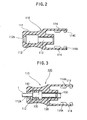
- Fig. 2 is a sectional view of the housing 110 of the optical connector 100, and the structure of the housing 110 will be detailed with the reference to Fig. 1 and Fig. 2.
- the housing 110 has at its rear part a holding portion 111 formed to be easily held by two fingers (for example, a thumb and an index finger) and this holding portion 111 has at its middle part a hollowed space 112 for accommodating a ferrule assembly comprising the ferrule 120, a flange portion 130, and a deflection spring 140 (hereafter referred to as a ferrule assembly accommodating space 112).
- the central part of the rear end of the ferrule assembly accommodating space 112 is provided with an opening 112A through which the optical cable 1 is allowed to extend out.
- the housing 110 has at its virtually middle part a through passage 113, which is formed to communicate with the ferrule assembly accommodating space 112 and whose inner diameter is large enough to hold the front end part of the ferrule 120 and the rear end part of a split sleeve 150 (hereafter referred to as a ferrule holding through passage 113).
- the housing has a pair of elastic arms 114 for guiding and locking the mate connector (hereafter referred to as guide/lock elastic arm 114) on the side of and the outer side of the mate connector, for example, the optical semiconductor module 200.
- the guide/lock elastic arm 114 formed as a cantilever allowed elastically to open a little outward, is integrated with the body of the housing 110.
- This guide/lock elastic arm 114 has on the inner wall of its front end part a lock protuberance 114A for locking the coupled optical semiconductor module 200 as the mate connector.
- the lock protuberance 114A has guide grooves 114B, 114C formed in a cross as a whole for guiding and locating the ferrule 220 of the optical semiconductor module 200 as the mating connector. As described in later, these guide grooves 114B, 114C guide and locate the mate connector regarding its vertical and lateral directions respectively in Fig.
- the guide pattern of these grooves according to the present invention is not limited to a cross, and the grooves may be structured in various patterns so that they work as plural axes guides for guiding and locating the mate connector in plural directions.
- Such guide patterns as T-shape, etc. may be allowable.
- the detailed structure of the housing 210 of the optical semiconductor module 200 will hereafter be described with the reference of Fig. 2 illustrating a perspective view thereof clearly.
- the housing 210 has, on both sides 211A of its coupling portion 211, protuberant ridges 211B, 211C engaging respectively with the guide grooves 114B, 114C provided to the lock protuberance 114A arranged on the inner wall of the front end part of the guide/lock elastic arm 114 of the housing 110 of the optical connector 100.
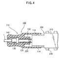
- an operator holds the holding portion 111 of the rear part of the housing 110 of the optical connector 100, for example, with his thumb and index finger and push the optical connector 100 into the optical semiconductor module 200 so that the guide grooves 114B of the guide/lock elastic arms 114 on both sides of the front portion of the housing 110 engage with the protuberant stripes provided to both sides 211A of the coupling portion 211 of the housing 210 of the optical semiconductor module 200.
- the guide/lock elastic arm 114 is elastically deflected a little outward due to the effect of a cam face at the front end of the lock protuberance 114A which is pushed outward by the protuberant stripe 211C on the housing 210 of the optical semiconductor module 200, and the front half of the lock protuberances 114A is allowed to ride over the protuberant ridge 211C, and at the moment when the ride-over has finished, i.e., the guide groove 114C has engaged with the protuberant ridge 211C, the elastic force of deflecting the guide/lock elastic arm 114 returns the guide/lock elastic arm 114 to its original closing position.
- Fig. 4 is a sectional view illustrating how the optical connector 100 and the optical semiconductor module 200 which couple with and lock up each other.
- a type of mate connector to be coupled with an optical connector is described as a type of optical semiconductor module placed on a printed circuit board, but the present invention, not being limited to such type of mate connector, may be applied to such type of mate connector to be connected to an optical cable.
- the optical connector has on its housing side a guide/lock elastic arm and the optical semiconductor module as the mate connector has on its housing side a protuberant stripe engaging with the guide/lock elastic arm, but the roles of the optical connector and the mate connector for the lock mechanism are interchangeable and therefore the present invention, not being limited to the embodiment above, for example, may be applied to such a case that a mate connector and an optical connector have on their housing sides a similar guide/lock elastic arm and a similar protuberant ridge engaging with the guide/lock elastic arm respectively.
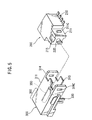
- Fig. 5 is a perspective view of a constitution of a shape adapting connector and an optical semiconductor module.
- Figs. 6A, 6B, 6C are respectively front, side, and plan views illustrating how the shape adapting connector and the optical semiconductor module shown in Fig. 5 are coupled with each other.
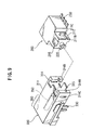
- Fig. 7 is a perspective view of constitution of a shape adapting connector of the present invention and an optical semiconductor module, and Figs. 8A, 8B, 8C are respectively front, side, and plan views illustrating how the shape adapting connector and the optical semiconductor module shown in Fig. 7 are coupled with each other.
- Fig. 9 is a perspective view of another constitution of a shape adapting connector of the present invention and an optical semiconductor module, and Figs.
- FIGS. 10A, 10B, 10C are respectively front, side, and plan views illustrating the shape adapting connector shown in Fig. 9.
- Figs. 5 to 10 show embodiments of an adapter to which the present invention is applied for an optical semiconductor module and a MU connector specified in JIS.
- the adapter 300 has at its center a split sleeve 350 held by a housing 311, a coupling portion on the side of the MU connector, coupling portions 314, 315 to be coupled with an optical semiconductor module 200, and a protuberance 330 fixed to board (or threaded protuberance fixed to side wall) provided to the bottom of the adapter 300.
- the coupling portion 314 is a guide/lock elastic arm of the present invention, and the coupling portion 315 is an auxiliary guide.
- a ferrule 220 protruding out of the module 200 is inserted into the split sleeve 350.
- a ferrule of the MU connector is inserted into the split sleeve 350 and thereby the ferrule on the module side and the MU connector are coupled with each other by a constant force due to a spring in the MU connector.
- the connector of Fig. 5 which is outside the scope of the invention, comprises a coupling portion 211 which is structured to have only a protuberant ridge 211C for locking an elastic arm 314 of an optical connector.
- An elastic arm 314 is formed to have a groove 314C corresponding to the protuberant ridge 211C.
- the guide of an optical connector is regulated by coupling an auxiliary guide 315 of an adapter 300 with an auxiliary guide recess 215 formed on the coupling portion 211.
- a coupling portion 211 is provided with a protuberant ridge 211B and a protuberant ridge 211C which are disposed in a T-shape.
- An elastic arm 314 is formed to have grooves 314B, 314C corresponding to the protuberant ridges 211B, 211C respectively.
- a coupling portion 211 is provided with a protuberant ridge 211B and a protuberant ridge 211C which are disposed in a L-shape.
- An elastic arm 314 is formed to have grooves 314B, 314C corresponding to the protuberant ridges 211B, 211C respectively.
- An embodiment constituted in this way as shown in Fig. 1 and Fig.7, can do without an auxiliary guide recess 215 formed on the coupling portion 211 and an auxiliary guide 315 of an adapter 300.
- the present invention allows a guide/lock elastic arm to serve as a member for guiding a mate connector to be correctly coupled with and for locking the coupling, the operability during the coupling has been improved without increasing the number of components.
- plural axes guides formed at a guide/lock elastic arm for guiding and locating in plural directions work to restrict the alignment of the ferrules after the coupling in plural directions including vertical and longitudinal directions, that is, in the directions of plural axes, the coupling and alignment can be kept more stabilized.
Landscapes
- Physics & Mathematics (AREA)
- General Physics & Mathematics (AREA)
- Optics & Photonics (AREA)
- Engineering & Computer Science (AREA)
- Microelectronics & Electronic Packaging (AREA)
- Optical Couplings Of Light Guides (AREA)
- Semiconductor Lasers (AREA)
- Mechanical Coupling Of Light Guides (AREA)
Claims (10)
- Optisches Halbleitermodul, das mit einem Gehäuse (210) versehen ist, welches optische Kopplungs- bzw. Kupplungsmittel aufweist, umfassend ein optisches Halbleiterelement und eine Modulmuffe bzw. -hülse (220), die eine optische Faser darin aufnimmt,
wobei ein Abschnitt des Gehäuses (210), welcher die Modulhülse (220) hält, ausgebildet ist, um ein mechanischer Kopplungsabschnitt (211) zum mechanischen Koppeln mit einem optischen Verbinder bzw. Steckverbinder (100; 300) zu sein, der eine Verbinderhülse (120) aufweist,
wobei der koppelnde bzw. Kopplungsabschnitt (211) mit ersten länglichen Regulierungsmitteln (211C) zum Positionieren der Verbinderhülse (120) des optischen Verbinders (100) in der Richtung der optischen Achse der Modulhülse (220) versehen ist, die in dem Kopplungsabschnitt (211) gehalten ist, wenn der Kopplungsabschnitt (211) mit dem optischen Verbinder (100; 300) gekoppelt ist,
wobei sich die ersten Regulierungsmittel (211C) allgemein in einer Richtung orthogonal zu der optischen Achse der Modulhülse (220) erstrecken,
gekennzeichnet durch
zweite längliche Regulierungsmittel (211B) zum Ausrichten der Verbinderhülse (120) des optischen Verbinders (100; 300) in einer Richtung mit der optischen Achse der Modulhülse (220), die in dem Kopplungsabschnitt (211) gehalten ist, wenn der Kopplungsabschnitt (211) mit dem optischen Verbinder (100; 300) koppelt,
wobei sich die zweiten Regulierungsmittel (211B) allgemein in einer Richtung parallel zu der optischen Achse erstrecken, wobei die ersten Regulierungsmittel (211 C) und die zweiten Regulierungsmittel (211 B) auf bzw. an demselben Flächen- bzw. Seitenabschnitt (211A) des Kopplungsabschnitts (211) vorgesehen sind, so daß die ersten (211C) und zweiten (211 B) Regulierungsmittel fähig sind, mechanisch entsprechende erste Regulierungsmittel (114C) und zweite Regulierungsmittel (114B) zu ergreifen, die auf bzw. an der Innenwand eines elastischen Arms (114) des optischen Verbinders vorgesehen sind,
wobei die ersten Regulierungsmittel (211C) auch zum Verriegeln des optischen Verbinders (100; 300) mit dem Kopplungsabschnitt (211) funktioniert,
wobei die zweiten Regulierungsmittel (211B) auf bzw. an dem Modul zum Führen der Kopplung des optischen Verbinders (100; 300) mit dem Kopplungsabschnitt (211) entlang der optischen Achsrichtung funktioniert. - Optisches Halbleitermodul gemäß Anspruch 1, wobei die zweiten Regulierungsmittel (211B) fungieren bzw. funktionieren, um die Ausrichtung des Verbinders und der Modulhülsen (120, 220) in einer Richtung senkrecht zu der Richtung der optischen Achse des Verbinders und der Modulhülsen (120, 220) zu halten, wenn die Kopplung mit dem optischen Verbinder (100; 300) vervollständigt wird.
- Optisches Halbleitermodul gemäß Anspruch 1 oder Anspruch 2, wobei die zweiten Regulierungsmittel (211 B) einen Abschnitt aufweisen, der sich über die ersten Regulierungsmittel (211 C) in einer Richtung eines Koppelns mit dem optischen Verbinder (100; 300) erstreckt.
- Optisches Halbleitermodul gemäß Anspruch 1 oder Anspruch 2 oder Anspruch 3,
wobei die ersten Regulierungsmittel (211 C) und die zweiten Regulierungsmittel (211B) in der Form von kreuzförmigen oder T-förmigen oder L-förmigen vorragenden Rippen bzw. Stegen vorliegen. - Optisches Halbleitermodul gemäß Anspruch 1 oder Anspruch 2 oder Anspruch 3,
wobei der Kopplungsabschnitt (211) eine Breite kleiner als ein anderer Abschnitt des Gehäuses (210) aufweist. - Optisches Halbleitermodul gemäß einem der Ansprüche 1 bis 5, wobei der Kopplungsabschnitt (211) mit einer Vertiefung bzw. Aussparung (215) auf bzw. an einem Seitenabschnitt davon versehen ist, auf welchem Seitenabschnitt die Regulierungsmittel nicht vorgesehen sind, wobei sich die Vertiefung (215) nach rückwärts von dem Vorderende des Kopplungsabschnitts (211) erstreckt, wobei die Vertiefung (215) adaptiert ist, um ein vorragendes Stück (315) aufzunehmen, das sich von dem Vorderende des optischen Verbinders (300) erstreckt.
- Optischer Verbinder bzw. Steckverbinder, umfassend ein Gehäuse (110), das einen eine Hülse bzw. Muffe haltenden Abschnitt (111) zum Halten einer Verbinderhülse bzw. -muffe (120) aufweist, die mit einer optischen Faser verbunden ist,
wobei das Gehäuse (110) mit einem elastischen Arm (114) an einer Außenseite eines koppelnden bzw. Kopplungsende zum Koppeln mit einem optischen Modul (200) versehen ist,
wobei der elastische Arm (114) mit ersten länglichen Regulierungsmitteln (114C) zum Positionieren der Verbinderhülse (120), die in dem Hülsenhalteabschnitt (111) gehalten ist, in der Richtung der optischen Achse einer Modulhülse (220) des optischen Moduls (200) versehen ist, wenn er mit dem optischen Modul (200) mechanisch gekoppelt ist,
wobei sich die ersten Regulierungsmittel (114C) allgemein in einer Richtung senkrecht zu der Richtung der optischen Achse der Verbinderhülse (120) erstrecken,
gekennzeichnet durch
zweite längliche Regulierungsmittel (114B) zum Ausrichten der Verbinderhülse (120), die in dem Hülsenhalteabschnitt (111) gehalten ist, mit der optischen Achse der Modulhülse (220) in dem optischen Modul (200), wenn er mit dem optischen Modul (200) gekoppelt ist,
wobei sich die zweiten Regulierungsmittel (114B) allgemein in einer Richtung parallel zu der optischen Achse der Verbinderhülse (120) erstrecken, wobei die ersten Regulierungsmittel (114C) und die zweiten Regulierungsmittel (114B) auf bzw. an der Innenwand des elastischen Arms (114) vorgesehen sind, um fähig zu sein, mechanisch entsprechende erste und zweite Regulierungsmittel auf bzw. an einer Seitenfläche bzw. Seite des optischen Moduls (200) zu ergreifen,
wobei die ersten Regulierungsmittel (114C) auch funktionieren bzw. fungieren, um die Kopplung mit dem optischen Modul (200) zu verriegeln,
wobei die zweiten Regulierungsmittel (114B) funktionieren, um das Zusammenpassen des optischen Moduls (200) mit dem Kopplungsende entlang der Richtung der optischen Achse zu führen. - Optischer Verbinder gemäß Anspruch 7, wobei der Verbinder und die Modulhülsen (120, 220) über eine gespaltene Hülse (150) gekoppelt sind, die in dem Gehäuse (110) gehalten ist.
- Optischer Verbinder, umfassend ein Gehäuse, das einen Hülsenhalteabschnitt zum Halten einer Verbinderhülse bzw. -muffe aufweist, die mit einer optischen Faser verbunden ist,
wobei das Gehäuse mit einem koppelnden bzw. Kopplungsabschnitt an einer Außenseite eines Kopplungsendes zum Koppeln mit einem optischen Modul versehen ist,
wobei der Kopplungsabschnitt mit ersten länglichen Regulierungsmitteln zum Positionieren einer Modulhülse bzw. -muffe des optischen Moduls in der Richtung der optischen Achse der Verbinderhülse versehen ist, die in dem Kopplungsabschnitt gehalten ist, wenn der Kopplungsabschnitt mit dem optischen Modul gekoppelt ist,
wobei sich die ersten Regulierungsmittel im allgemeinen in einer Richtung senkrecht zu der optischen Achse der Verbinderhülse erstrecken,
gekennzeichnet durch
zweite längliche Regulierungsmittel zum Ausrichten der Modulhülse des optischen Moduls in einer Richtung mit der optischen Achse der Verbinderhülse, die in dem Kopplungsabschnitt gehalten ist, wenn der Kopplungsabschnitt mit dem optischen Modul gekoppelt ist,
wobei sich die zweiten Regulierungsmittel allgemein in einer Richtung parallel zu der optischen Achse erstrecken, wobei die ersten Regulierungsmittel und die zweiten Regulierungsmittel auf bzw. an demselben Flächen bzw. Seitenabschnitt des Kopplungsabschnitts vorgesehen sind, um fähig zu sein, mechanisch entsprechende erste Regulierungsmittel und zweite Regulierungsmittel zu ergreifen, die an der Innenwand eines elastischen Arms des optischen Moduls vorgesehen sind,
wobei die ersten Regulierungsmittel auch funktionieren bzw. fungieren, um den Kopplungsabschnitt mit dem optischen Modul zu koppeln,
wobei die zweiten Regulierungsmittel funktionieren, um die Kopplung des Kopplungsabschnitts mit dem optischen Modul entlang der optischen Achse zu führen. - Optisches Halbleitermodul, versehen mit einem Gehäuse, welches optische Kopplungsmittel aufweist, umfassend ein optisches Halbleiterelement und eine Modulhülse bzw. -muffe, die eine optische Faser darin aufnimmt,
wobei ein Abschnitt des Gehäuses, der die Modulhülse hält, mit einem elastischen Arm an einer Außenseite eines Kopplungsendes zum Koppeln mit einem optischen Verbinder versehen ist,
wobei der elastische Arm mit ersten länglichen Regulierungsmitteln zum Positionieren einer Modulhülse versehen ist, die in dem Hülsenhalteabschnitt in der Richtung der optischen Achse einer Verbinderhülse des optischen Verbinders gehalten ist, wenn der optische Verbinder gekoppelt ist,
wobei sich die ersten Regulierungsmittel allgemein in einer Richtung senkrecht zu der Richtung der optischen Achse erstrecken,
gekennzeichnet durch
zweite längliche Regulierungsmittel zum Ausrichten der Modulhülse, die in dem Hülsenhalteabschnitt in einer Richtung, mit der Richtung der Achse der Verbinderhülse des optischen Verbinders gehalten ist, wenn mit dem optischen Verbinder gekoppelt wird, wobei sich die zweiten Regulierungsmittel allgemein in einer Richtung parallel zu der optischen Achse erstrecken,
wobei die ersten Regulierungsmittel und die zweiten Regulierungsmittel an der Innenwand desselben elastischen Arms vorgesehen sind, um fähig zu sein, mechanisch entsprechende erste und zweite Regulierungsmittel auf bzw. an einer Seitenfläche bzw. Seite des optischen Moduls zu ergreifen,
wobei die ersten Regulierungsmittel auch funktionieren bzw. fungieren, um die Kopplung mit dem optischen Verbinder zu verriegeln,
wobei die zweiten Regulierungsmittel funktionieren, um die Kopplung des optischen Verbinders mit dem Kopplungsende entlang der optischen Achsrichtung zu führen.
Applications Claiming Priority (2)
| Application Number | Priority Date | Filing Date | Title |
|---|---|---|---|
| JP4148398 | 1998-02-24 | ||
| JP10041483A JP3078254B2 (ja) | 1998-02-24 | 1998-02-24 | 光半導体モジュール、光コネクタ及び形状変換光コネクタ構造 |
Publications (2)
| Publication Number | Publication Date |
|---|---|
| EP0938006A1 EP0938006A1 (de) | 1999-08-25 |
| EP0938006B1 true EP0938006B1 (de) | 2005-11-16 |
Family
ID=12609603
Family Applications (1)
| Application Number | Title | Priority Date | Filing Date |
|---|---|---|---|
| EP99102763A Expired - Lifetime EP0938006B1 (de) | 1998-02-24 | 1999-02-23 | Strukturen für optisches Halbleitermodul, optischen Steckverbinder und formadaptiven optischen Steckverbinder |
Country Status (5)
| Country | Link |
|---|---|
| US (1) | US6135644A (de) |
| EP (1) | EP0938006B1 (de) |
| JP (1) | JP3078254B2 (de) |
| CA (1) | CA2262241A1 (de) |
| DE (1) | DE69928303T2 (de) |
Families Citing this family (23)
| Publication number | Priority date | Publication date | Assignee | Title |
|---|---|---|---|---|
| US6435730B1 (en) * | 1998-05-06 | 2002-08-20 | The Whitaker Corporation | Optical fiber connector with improved ferrule float feature |
| JP3455168B2 (ja) * | 1999-07-19 | 2003-10-14 | 古河電気工業株式会社 | レセプタクルモジュール |
| JP2001083370A (ja) * | 1999-09-13 | 2001-03-30 | Mitsubishi Electric Corp | 表面実装型光デバイス |
| US6409393B1 (en) * | 2000-02-18 | 2002-06-25 | Molex Incorporated | Fiber optic connector assembly and method of assembly |
| US6624507B1 (en) * | 2000-05-09 | 2003-09-23 | National Semiconductor Corporation | Miniature semiconductor package for opto-electronic devices |
| US6579015B2 (en) * | 2001-02-01 | 2003-06-17 | Fitel Usa Corporation | Optical connector ferrule having a multiple-angled pedestal |
| US7073953B2 (en) | 2001-08-31 | 2006-07-11 | Amphenol Corporation | Modular fiber optic connection system |
| US7090412B2 (en) * | 2002-08-02 | 2006-08-15 | Sumitomo Electric Industries, Ltd. | Optical module |
| WO2004027482A1 (de) * | 2002-09-23 | 2004-04-01 | Huber+Suhner Ag | Anschlussvorrichtung zum lösbaren verbinden wenigstens eines lichtwellenleiters mit wenigstens einem optoelektronischen bauelement sowie verfahren zum montieren einer solchen anschlussvorrichtung |
| US20040076380A1 (en) * | 2002-10-22 | 2004-04-22 | Autonetworks Technologies, Ltd. | Optical connector |
| US7486524B2 (en) * | 2003-03-03 | 2009-02-03 | Finisar Corporation | Module housing for improved electromagnetic radiation containment |
| US7004643B1 (en) | 2003-10-03 | 2006-02-28 | Yazaki North America, Inc. | Fiber optic coupling device |
| DE102004013905B4 (de) * | 2004-03-17 | 2006-01-26 | Adc Gmbh | Glasfaser-Steckverbindung |
| JP3979408B2 (ja) * | 2004-08-30 | 2007-09-19 | ミツミ電機株式会社 | カメラモジュール用コネクタロック装置 |
| NL2000456C1 (nl) * | 2007-01-29 | 2008-07-30 | Genexis B V | Inrichting voor het aansluiten van apparaten op optische vezels en werkwijze voor het vormen van een dergelijke inrichting. |
| CN105283786B (zh) | 2013-01-18 | 2017-03-15 | 莫列斯有限公司 | 光纤互连组件 |
| TW201610500A (zh) * | 2014-09-10 | 2016-03-16 | 鴻海精密工業股份有限公司 | 光纖耦合連接器 |
| CN108351473B (zh) * | 2015-10-12 | 2020-09-08 | 3M创新有限公司 | 套管、对准框架和连接器 |
| JP2017138535A (ja) * | 2016-02-05 | 2017-08-10 | 富士通コンポーネント株式会社 | フェルール接続部品 |
| US11169332B2 (en) * | 2017-08-18 | 2021-11-09 | Commscope Technologies Llc | Fiber optic connector with unitary housing and fiber optic connector assembly |
| JP2019152729A (ja) * | 2018-03-02 | 2019-09-12 | ヒロセ電機株式会社 | 光ファイバプラグ及び光ファイバ接続組立体 |
| US10948663B2 (en) | 2018-06-05 | 2021-03-16 | Panduit Corp. | Small form factor multi-fiber connector |
| TWI826055B (zh) * | 2021-10-28 | 2023-12-11 | 日商白山股份有限公司 | 光連接器及插頭 |
Family Cites Families (16)
| Publication number | Priority date | Publication date | Assignee | Title |
|---|---|---|---|---|
| DE2939231C2 (de) | 1979-09-27 | 1983-01-20 | Siemens AG, 1000 Berlin und 8000 München | Mehrfachstecker zum Anschluß einer Glasfaserleitung an einen opto-elektrischen Baustein |
| JPS5890607A (ja) * | 1981-11-25 | 1983-05-30 | Mitsubishi Electric Corp | 光回路の結合構造 |
| JPS58109001A (ja) * | 1981-12-22 | 1983-06-29 | ユニチカ株式会社 | 靴用基布 |
| JPS59148762A (ja) * | 1983-02-10 | 1984-08-25 | Ajinomoto Co Inc | アゼチジノン誘導体 |
| JPS63101407A (ja) * | 1986-10-20 | 1988-05-06 | Kanegafuchi Chem Ind Co Ltd | 耐熱性樹脂 |
| US4840451A (en) * | 1987-12-08 | 1989-06-20 | Molex Incorporated | Shielded fiber optic connector assembly |
| US5042891A (en) | 1990-06-21 | 1991-08-27 | Amp Incorporated | Active device mount assembly with interface mount for push-pull coupling type optical fiber connectors |
| DE4114156A1 (de) | 1991-04-30 | 1992-11-05 | Burndy Deutschland | Steckverbinder fuer lichtwellenleiter |
| JPH05181890A (ja) * | 1992-01-07 | 1993-07-23 | Oki Electric Ind Co Ltd | 自動取引装置 |
| JPH07192215A (ja) * | 1993-12-27 | 1995-07-28 | Toshiba Corp | バルク型磁気ヘッド |
| JPH07242711A (ja) * | 1994-03-04 | 1995-09-19 | Kuraray Co Ltd | メタクリル酸メチル共重合体 |
| JPH07266108A (ja) * | 1994-03-25 | 1995-10-17 | Richiko Kobayashi | チャック装置 |
| JP3316727B2 (ja) * | 1995-07-27 | 2002-08-19 | 日本電気エンジニアリング株式会社 | 光コネクタ |
| JPH09211276A (ja) * | 1996-02-05 | 1997-08-15 | Mitsubishi Electric Corp | 光モジュールとこれを用いた光接続装置 |
| JPH09265026A (ja) * | 1996-03-28 | 1997-10-07 | Oki Electric Ind Co Ltd | 光結合器および光結合器の製造方法 |
| JP3127951B2 (ja) * | 1996-07-19 | 2001-01-29 | 日本電気株式会社 | 半導体装置及びその製造方法 |
-
1998
- 1998-02-24 JP JP10041483A patent/JP3078254B2/ja not_active Expired - Fee Related
-
1999
- 1999-02-17 US US09/251,444 patent/US6135644A/en not_active Expired - Lifetime
- 1999-02-22 CA CA002262241A patent/CA2262241A1/en not_active Abandoned
- 1999-02-23 DE DE69928303T patent/DE69928303T2/de not_active Expired - Fee Related
- 1999-02-23 EP EP99102763A patent/EP0938006B1/de not_active Expired - Lifetime
Also Published As
| Publication number | Publication date |
|---|---|
| DE69928303D1 (de) | 2005-12-22 |
| EP0938006A1 (de) | 1999-08-25 |
| CA2262241A1 (en) | 1999-08-24 |
| US6135644A (en) | 2000-10-24 |
| JP3078254B2 (ja) | 2000-08-21 |
| JPH11237534A (ja) | 1999-08-31 |
| DE69928303T2 (de) | 2006-08-10 |
Similar Documents
| Publication | Publication Date | Title |
|---|---|---|
| EP0938006B1 (de) | Strukturen für optisches Halbleitermodul, optischen Steckverbinder und formadaptiven optischen Steckverbinder | |
| EP1148366B1 (de) | Glasfaserstecker mit Exzentrizitätsanpassung | |
| JP3801464B2 (ja) | ハイブリッドコネクタ | |
| EP1170609B1 (de) | Hybrider Steckverbinder und Verfahren zu seiner Herstellung | |
| US5619604A (en) | Multi-fiber optical connector | |
| US6485192B1 (en) | Optical device having an integral array interface | |
| US5404416A (en) | Optical connector plug | |
| KR100319033B1 (ko) | 커넥터 조립체 | |
| EP1170612B1 (de) | Hybrider Steckverbinder für optische und elektrische Steckverbindungen | |
| US20040101265A1 (en) | Tool to remove a ferrule from a receptacle | |
| JPH087303B2 (ja) | 光ファイバ・コネクタ・ハウジング装置及び光アセンブリ | |
| JPH10123360A (ja) | 光ファイバ接続具ジャック及びその接続具システム | |
| TW201821842A (zh) | 可改變對接極性之光纖連接器 | |
| EP0938002B1 (de) | Optischer Steckverbinder | |
| JP2008026647A (ja) | 光レセプタクルハウジング、光コネクタレセプタクル及び光機器 | |
| US12153265B2 (en) | Ferrule, optical connector, and optical connector module | |
| US20040101253A1 (en) | Receptacle for receiving a ferrule | |
| US6382842B1 (en) | Plug-in optical connector with wrong plugging prevention key | |
| US20240411088A1 (en) | Ferrule holding structure | |
| US7211728B2 (en) | Optical cage system preventing insertion of incorrect module | |
| EP1257012A2 (de) | Optischer Steckverbinder | |
| JPH1068842A (ja) | 光コネクタ | |
| US20250306292A1 (en) | Optical module and optical connection structure | |
| US20230113680A1 (en) | Optical connector | |
| US20250035864A1 (en) | Optical connector and optical connector module |
Legal Events
| Date | Code | Title | Description |
|---|---|---|---|
| PUAI | Public reference made under article 153(3) epc to a published international application that has entered the european phase |
Free format text: ORIGINAL CODE: 0009012 |
|
| AK | Designated contracting states |
Kind code of ref document: A1 Designated state(s): DE FR GB IT NL SE |
|
| AX | Request for extension of the european patent |
Free format text: AL;LT;LV;MK;RO;SI |
|
| 17P | Request for examination filed |
Effective date: 19991007 |
|
| AKX | Designation fees paid |
Free format text: DE FR GB IT NL SE |
|
| 17Q | First examination report despatched |
Effective date: 20000904 |
|
| GRAP | Despatch of communication of intention to grant a patent |
Free format text: ORIGINAL CODE: EPIDOSNIGR1 |
|
| RIN1 | Information on inventor provided before grant (corrected) |
Inventor name: MATSUMOTO, TATEOMI Inventor name: TSUCHIDA, MASAHIRO Inventor name: NAKAMURA, TSUTOMU Inventor name: NAITO, KATSUYOSHI Inventor name: HAKOGI, HIRONAO |
|
| GRAS | Grant fee paid |
Free format text: ORIGINAL CODE: EPIDOSNIGR3 |
|
| RIN1 | Information on inventor provided before grant (corrected) |
Inventor name: MATSUMOTO, TATEOMI Inventor name: TSUCHIDA, MASAHIRO Inventor name: NAKAMURA, TSUTOMU Inventor name: NAITO, KATSUYOSHI Inventor name: HAKOGI, HIRONAO |
|
| RAP1 | Party data changed (applicant data changed or rights of an application transferred) |
Owner name: SUMITOMO ELECTRIC INDUSTRIES, LTD. Owner name: HIROSE ELECTRIC CO., LTD. Owner name: OKI ELECTRIC INDUSTRY CO., LTD. Owner name: FUJITSU LIMITED |
|
| GRAA | (expected) grant |
Free format text: ORIGINAL CODE: 0009210 |
|
| AK | Designated contracting states |
Kind code of ref document: B1 Designated state(s): DE FR GB IT NL SE |
|
| PG25 | Lapsed in a contracting state [announced via postgrant information from national office to epo] |
Ref country code: NL Free format text: LAPSE BECAUSE OF FAILURE TO SUBMIT A TRANSLATION OF THE DESCRIPTION OR TO PAY THE FEE WITHIN THE PRESCRIBED TIME-LIMIT Effective date: 20051116 Ref country code: IT Free format text: LAPSE BECAUSE OF FAILURE TO SUBMIT A TRANSLATION OF THE DESCRIPTION OR TO PAY THE FEE WITHIN THE PRE;WARNING: LAPSES OF ITALIAN PATENTS WITH EFFECTIVE DATE BEFORE 2007 MAY HAVE OCCURRED AT ANY TIME BEFORE 2007. THE CORRECT EFFECTIVE DATE MAY BE DIFFERENT FROM THE ONE RECORDED.SCRIBED TIME-LIMIT Effective date: 20051116 |
|
| REG | Reference to a national code |
Ref country code: GB Ref legal event code: FG4D |
|
| REF | Corresponds to: |
Ref document number: 69928303 Country of ref document: DE Date of ref document: 20051222 Kind code of ref document: P |
|
| PG25 | Lapsed in a contracting state [announced via postgrant information from national office to epo] |
Ref country code: SE Free format text: LAPSE BECAUSE OF FAILURE TO SUBMIT A TRANSLATION OF THE DESCRIPTION OR TO PAY THE FEE WITHIN THE PRESCRIBED TIME-LIMIT Effective date: 20060216 |
|
| NLV1 | Nl: lapsed or annulled due to failure to fulfill the requirements of art. 29p and 29m of the patents act | ||
| ET | Fr: translation filed | ||
| PLBE | No opposition filed within time limit |
Free format text: ORIGINAL CODE: 0009261 |
|
| STAA | Information on the status of an ep patent application or granted ep patent |
Free format text: STATUS: NO OPPOSITION FILED WITHIN TIME LIMIT |
|
| 26N | No opposition filed |
Effective date: 20060817 |
|
| REG | Reference to a national code |
Ref country code: GB Ref legal event code: 732E |
|
| REG | Reference to a national code |
Ref country code: FR Ref legal event code: TQ |
|
| PGFP | Annual fee paid to national office [announced via postgrant information from national office to epo] |
Ref country code: DE Payment date: 20090226 Year of fee payment: 11 |
|
| REG | Reference to a national code |
Ref country code: GB Ref legal event code: 732E Free format text: REGISTERED BETWEEN 20090507 AND 20090513 |
|
| PGFP | Annual fee paid to national office [announced via postgrant information from national office to epo] |
Ref country code: GB Payment date: 20090303 Year of fee payment: 11 |
|
| REG | Reference to a national code |
Ref country code: FR Ref legal event code: TP |
|
| PGFP | Annual fee paid to national office [announced via postgrant information from national office to epo] |
Ref country code: FR Payment date: 20090223 Year of fee payment: 11 |
|
| GBPC | Gb: european patent ceased through non-payment of renewal fee |
Effective date: 20100223 |
|
| REG | Reference to a national code |
Ref country code: FR Ref legal event code: ST Effective date: 20101029 |
|
| PG25 | Lapsed in a contracting state [announced via postgrant information from national office to epo] |
Ref country code: FR Free format text: LAPSE BECAUSE OF NON-PAYMENT OF DUE FEES Effective date: 20100301 |
|
| PG25 | Lapsed in a contracting state [announced via postgrant information from national office to epo] |
Ref country code: DE Free format text: LAPSE BECAUSE OF NON-PAYMENT OF DUE FEES Effective date: 20100901 |
|
| PG25 | Lapsed in a contracting state [announced via postgrant information from national office to epo] |
Ref country code: GB Free format text: LAPSE BECAUSE OF NON-PAYMENT OF DUE FEES Effective date: 20100223 |