EP0938035A2 - Elektromechanische Bedieneinrichtung - Google Patents
Elektromechanische Bedieneinrichtung Download PDFInfo
- Publication number
- EP0938035A2 EP0938035A2 EP99103186A EP99103186A EP0938035A2 EP 0938035 A2 EP0938035 A2 EP 0938035A2 EP 99103186 A EP99103186 A EP 99103186A EP 99103186 A EP99103186 A EP 99103186A EP 0938035 A2 EP0938035 A2 EP 0938035A2
- Authority
- EP
- European Patent Office
- Prior art keywords
- rotor
- pole
- stator
- poles
- operating device
- Prior art date
- Legal status (The legal status is an assumption and is not a legal conclusion. Google has not performed a legal analysis and makes no representation as to the accuracy of the status listed.)
- Withdrawn
Links
Images


Classifications
-
- G—PHYSICS
- G05—CONTROLLING; REGULATING
- G05G—CONTROL DEVICES OR SYSTEMS INSOFAR AS CHARACTERISED BY MECHANICAL FEATURES ONLY
- G05G9/00—Manually-actuated control mechanisms provided with one single controlling member co-operating with two or more controlled members, e.g. selectively, simultaneously
- G05G9/02—Manually-actuated control mechanisms provided with one single controlling member co-operating with two or more controlled members, e.g. selectively, simultaneously the controlling member being movable in different independent ways, movement in each individual way actuating one controlled member only
- G05G9/04—Manually-actuated control mechanisms provided with one single controlling member co-operating with two or more controlled members, e.g. selectively, simultaneously the controlling member being movable in different independent ways, movement in each individual way actuating one controlled member only in which movement in two or more ways can occur simultaneously
- G05G9/047—Manually-actuated control mechanisms provided with one single controlling member co-operating with two or more controlled members, e.g. selectively, simultaneously the controlling member being movable in different independent ways, movement in each individual way actuating one controlled member only in which movement in two or more ways can occur simultaneously the controlling member being movable by hand about orthogonal axes, e.g. joysticks
-
- B—PERFORMING OPERATIONS; TRANSPORTING
- B64—AIRCRAFT; AVIATION; COSMONAUTICS
- B64C—AEROPLANES; HELICOPTERS
- B64C13/00—Control systems or transmitting systems for actuating flying-control surfaces, lift-increasing flaps, air brakes, or spoilers
- B64C13/02—Initiating means
- B64C13/04—Initiating means actuated personally
- B64C13/042—Initiating means actuated personally operated by hand
- B64C13/0421—Initiating means actuated personally operated by hand control sticks for primary flight controls
-
- G—PHYSICS
- G05—CONTROLLING; REGULATING
- G05G—CONTROL DEVICES OR SYSTEMS INSOFAR AS CHARACTERISED BY MECHANICAL FEATURES ONLY
- G05G9/00—Manually-actuated control mechanisms provided with one single controlling member co-operating with two or more controlled members, e.g. selectively, simultaneously
- G05G9/02—Manually-actuated control mechanisms provided with one single controlling member co-operating with two or more controlled members, e.g. selectively, simultaneously the controlling member being movable in different independent ways, movement in each individual way actuating one controlled member only
- G05G9/04—Manually-actuated control mechanisms provided with one single controlling member co-operating with two or more controlled members, e.g. selectively, simultaneously the controlling member being movable in different independent ways, movement in each individual way actuating one controlled member only in which movement in two or more ways can occur simultaneously
- G05G9/047—Manually-actuated control mechanisms provided with one single controlling member co-operating with two or more controlled members, e.g. selectively, simultaneously the controlling member being movable in different independent ways, movement in each individual way actuating one controlled member only in which movement in two or more ways can occur simultaneously the controlling member being movable by hand about orthogonal axes, e.g. joysticks
- G05G2009/0474—Manually-actuated control mechanisms provided with one single controlling member co-operating with two or more controlled members, e.g. selectively, simultaneously the controlling member being movable in different independent ways, movement in each individual way actuating one controlled member only in which movement in two or more ways can occur simultaneously the controlling member being movable by hand about orthogonal axes, e.g. joysticks characterised by means converting mechanical movement into electric signals
-
- G—PHYSICS
- G05—CONTROLLING; REGULATING
- G05G—CONTROL DEVICES OR SYSTEMS INSOFAR AS CHARACTERISED BY MECHANICAL FEATURES ONLY
- G05G9/00—Manually-actuated control mechanisms provided with one single controlling member co-operating with two or more controlled members, e.g. selectively, simultaneously
- G05G9/02—Manually-actuated control mechanisms provided with one single controlling member co-operating with two or more controlled members, e.g. selectively, simultaneously the controlling member being movable in different independent ways, movement in each individual way actuating one controlled member only
- G05G9/04—Manually-actuated control mechanisms provided with one single controlling member co-operating with two or more controlled members, e.g. selectively, simultaneously the controlling member being movable in different independent ways, movement in each individual way actuating one controlled member only in which movement in two or more ways can occur simultaneously
- G05G9/047—Manually-actuated control mechanisms provided with one single controlling member co-operating with two or more controlled members, e.g. selectively, simultaneously the controlling member being movable in different independent ways, movement in each individual way actuating one controlled member only in which movement in two or more ways can occur simultaneously the controlling member being movable by hand about orthogonal axes, e.g. joysticks
- G05G2009/04774—Manually-actuated control mechanisms provided with one single controlling member co-operating with two or more controlled members, e.g. selectively, simultaneously the controlling member being movable in different independent ways, movement in each individual way actuating one controlled member only in which movement in two or more ways can occur simultaneously the controlling member being movable by hand about orthogonal axes, e.g. joysticks with additional switches or sensors on the handle
-
- Y—GENERAL TAGGING OF NEW TECHNOLOGICAL DEVELOPMENTS; GENERAL TAGGING OF CROSS-SECTIONAL TECHNOLOGIES SPANNING OVER SEVERAL SECTIONS OF THE IPC; TECHNICAL SUBJECTS COVERED BY FORMER USPC CROSS-REFERENCE ART COLLECTIONS [XRACs] AND DIGESTS
- Y02—TECHNOLOGIES OR APPLICATIONS FOR MITIGATION OR ADAPTATION AGAINST CLIMATE CHANGE
- Y02T—CLIMATE CHANGE MITIGATION TECHNOLOGIES RELATED TO TRANSPORTATION
- Y02T50/00—Aeronautics or air transport
- Y02T50/40—Weight reduction
Definitions
- the invention relates to an electromechanical control device for use in aircraft, ships, vehicles, any type of machine etc. a stator and a rotor, which are relative by means of an operating lever are inclined to each other by an azimuth angle.
- DE 195 01 439 A1 describes an electromechanical control device for one- or multi-dimensional detection of positions or angles of rotation Control of vehicles, operation of hoists and interactive Use of devices known for example from data processing technology.
- the known operating device is for multidimensional rotation angle detection designed so that a moving part of the device with a Electromagnetically generated torque can be applied.
- the Known electromechanical control device consists of a stationary part, namely the stator in the form of a yoke with a yoke base and Yoke flanks, pole pieces with grooves and teeth and the yoke base surrounding coils on the one hand and the movable part in the form of a rotor with excitation part, upper and lower pole disc and control lever on the other.
- the rotor points at a simple one Axial bearing one degree of freedom, two with a gimbal bearing with a spherical head bearing, three rotational degrees of freedom.
- the exciter part of the rotor is a cylindrical ring made of permanent magnetic Material that is magnetized in the axial direction.
- the rotor can be tilted by an azimuth angle, centrally, using the operating lever between several pole pieces placed on the symmetrical Eisenjoch arranged.
- On each yoke arm of the known control device arranged at least one electrical coil.
- the rotor is layered so that a middle area on its top and bottom of the two Pole discs is edged.
- the pole pieces surrounding the rotor face one groove each in height so that this retires with the middle part of the rotor corresponds in height.
- Those that develop through the grooving Teeth above and below the grooving are therefore in the area in terms of their height the upper and lower pole disc.
- the invention has for its object an electromechanical control device to create, which is significantly smaller in size than that known electromechanical control device.
- Ferromagnetic base plate can be a stable base plate of any kind Materials are used, for example made of aluminum or plastic as a result of weight loss.
- Another advantage of the invention is that a constructive degree of freedom especially for increasing the force / torque formation in small Deflection angles of an operating lever of the operating device thereby created is that several disc elements with permanent magnet ring elements arranged between them can be arranged one above the other. It is advantageous also possible to adapt the forces to the respective Requirements already in the constructive design of the electromechanical Control device to be provided by suitable choice of the geometric Design of the poles, dimensioning of the pole coil, choice of the distance between the poles from the pivot point of the exciter arrangement and the choice of the same pair Angle of the poles to each other in the two pivot axes of the control lever.
- the pole or poles are preferably arranged in a ring so that they are in their Middle pick up the excitation arrangement, so that a due in the poles of the current-carrying conductor elements forming magnetic flux over the pathogen arrangement closes.
- the permanent magnet ring elements are preferred magnetized in the axial direction.
- the stator poles and the Disc elements of the rotor preferably consist of ferromagnetic Material.
- the conductor elements arranged in the grooves of the poles are preferably a component at least one coil of each pole, preferably the Coil is fed with a variable current according to amount and sign.
- the sides of the coils are particularly preferred in each case in the axial direction grooves arranged one above the other.
- the movable exciter arrangement in this case then two in the axial direction superimposed permanent magnet ring elements.
- the sides of the coils of the poles are in two grooves arranged one above the other in the axial direction, wherein the movable exciter arrangement preferably a disc-shaped permanent magnet ring element having.
- the poles which are preferably arranged in a ring, can be based on the respective one Axis of the force effect different geometrical designs and / or have embodiments of the respective coils.
- the poles arranged in a ring are particularly preferred, based on the respective axis of the force effect in a pair same, otherwise arranged different geometric angles.
- the poles arranged in a ring can preferably also be different Distances from the respective bearing or pivot or pivot point of the Have exciter arrangement and the disc elements of the exciter arrangement be elliptical.
- several are electrical in the slots of the poles separate coils arranged.
- the currents flowing through the coils are particularly preferably controlled or regulated.
- a control unit works with one this subsequent current control unit together.
- the control unit externally supplied signals abandoned. These are, for example, the pitch position and the roll position of the operating device as well as switch signals and State information.
- the current controller signals act on the actuator unit the control device via the current-carrying conductor elements in the grooves of the Pole of the stator.
- a particularly preferred multiple arrangement of permanent magnet disk elements is the force effect of the control device in this area elevated. This is done by multiplying the field influences on deflection, according to the number of slices.
- the pole arrangement and the Exciter arrangement are based on that from DE 195 01 439 A1 known operating device uses the terms stator and rotor been. In contrast to the technology indicated by this, these are intended here Terms only represent the contrast between fixed and flexible.
- the rotor is not determined by the rotation of a body around its axis. Rather, the control lever pivots the rotor or stator by changing the Angular position of this axis.
- FIG. 1 shows a sectional side view of a first embodiment of an electromechanical control device.
- the operating device has an operating lever 1. This is connected to an actuator unit 2. Compared to this, it can be tilted in different directions. This tiltability is created by a joint 30 within the actuator unit 2. On the one hand, this is connected to a mounting plate 31 of the actuator unit via a first joint element 32. On the other hand, it is connected to the operating lever 1 via a second joint element 33.
- the axis of this rotor 20 is the vertically drawn one Axis 14 of the control device. It is or must not be an axis of rotation for the Rotor 20.
- the rotor 20 has a metal ball element 23, in particular one Steel ball, with outer disc elements 21 and a middle element 24 on. These are in the axial direction, that is the direction of the drawn Axis, interrupted by permanent magnet ring elements 22. In the embodiment 1 are two such permanent magnet ring elements 22 provided.
- the permanent magnet ring elements are preferably in axially magnetized.
- the metal ball element 23 preferably consists of ferromagnetic material, especially steel.
- the rotor is movably arranged in the middle of a stator 10.
- the stator 10 has poles 11 surrounding the rotor 20 directly. These are essentially arranged in a ring around the rotor 20. They have more or less depth Grooves 12 on. At the location or within these grooves 12 are each live Conductor elements 13 arranged. The depth of the grooves 12 can also become zero, when using printed spools or flat spools.
- the poles made of ferromagnetic material, which due to the in the current-carrying conductor elements flowing current within the grooves of the The resulting magnetic flux poles across the center of the poles movably arranged exciter arrangement of the rotor 20 closes.
- the respective current-carrying conductor element arranged in the grooves 12 of the poles 11 13 is preferably part of at least one coil per pole 11. Such a coil is variable with an amount and sign Electricity fed.
- a permanent magnet ring element be arranged as an annular disc.
- the respective coil one Poles is supported with its sides in two arranged one above the other in the axial direction Grooves 12, only the coil being shown in FIG. 1.
- FIG. 2 A cross-sectional view of the actuator unit 2 is shown in FIG .
- the geometric design of the poles 11 is more clearly visible.
- the current-carrying conductor elements 13 are shown in dashed lines.
- the respective axis of the force effect for the annularly arranged poles can also be designed differently by appropriate selection of the geometric design of the poles and / or design of the coils with regard to their current-carrying conductor elements 13.
- the force effect in the two directions is the same if, as shown in FIG. 2, pairs of poles are formed which relate to the respective axis of the force effect, have pairs of different geometric angles of their arrangement within the actuator unit. This ensures that the peculiarities of the human hand are taken into account for the force effect, namely that a force away from the human body is stronger than that to the side.
- the poles 11 can be moved in the direction of the axis 14. Screws 15 and elongated holes 16 indicate this.
- the Pole 11 on the base plate 31 in the manner of a dovetail connection slidably mounted.
- the poles can also be used to adjust the symmetry or asymmetry. along an arc around axis 14 become
- FIG. 3 shows a further sectional view of the operating device according to FIG. 1.
- the poles can now be seen in the respective other cross-sectional view.
- the operating lever 1 can be deflected not only in the direction of the arrow according to FIG. 1 , but also in the direction of the arrow according to FIG. 3. This also allows the cordan joint 30.
- a plurality of these are provided one above the other with disk elements 21 of the metal ball element 23 arranged in between. This means a constructive degree of freedom to adapt to small deflection angles.
- the distance of the poles from the joint 30 as the excitation arrangement rotation and The bearing point can be varied in different ways. This can also an adjustment of the forces to the respective requirements of the individual case be made.
- poles it is also possible to mount the poles so that they can move in a circular direction the poles can be adjusted in both symmetrical and asymmetrical positions close.
- FIG. 4 shows a perspective view of the operating device according to FIG. 1.
- the arrangement of the spherical rotor 20 with the two permanent magnet ring elements 22 arranged above and below can be clearly seen. These are inserted into the metal ball element 23. This has the two outer (upper and lower) disc elements 21 and the middle element 24.
- the current-carrying conductor element 13 of the Stator 10 is illustrated. This is preferably an excitation coil Copper winding.
- the pole 11 or the poles 11 are preferably made of iron.
- FIG. 4 also clearly shows the spatial arrangement of the operating lever 1. This can be swiveled in different spatial directions and takes the metal ball element and thus the rotor 20 with it.
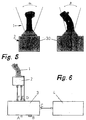
- the Panning options can be seen in FIG. 5.
- FIG. 5 shows the side view of the view according to FIG. 3 and the view according to FIG. 1 of the electromechanical control device.
- the possible deflection angles ⁇ and ⁇ based on the pivot point of the exciter arrangement in the form of the joint 30, are sketched in each case.
- the angle ⁇ can be chosen between -20 ° and + 20 ° with a maximum force F max of 50 N.
- the dimensions of the actuator unit are, for example, 130 mm by 165 mm.
- the height of the actuator unit can then be selected to be 95 mm.
- the pivot point in the form of the joint 30 is, for example, 140 mm at one Total height of the electromechanical control device of 261 mm.
- FIG. 6 shows the electrical interfaces between the electromechanical operator control device with actuator unit 2 and an electronics unit 3 and a data processing unit 4.
- the actuator unit 2 sends signals to the electronics unit 3 via a line F.
- the electronics unit in turn is connected to a power supply A and likewise supplies the actuator unit a line E with electricity.
- Another line D leads from the control lever 1 directly to the electronics unit. The deflection angle is recorded and transmitted via this.
- the electronics unit 3 is provided with an RS 232 interface B in order to to be able to connect a computer. Furthermore, it is over a line C, namely a data bus, in particular an aviation-specific one Data bus for avionics systems, with the data processing unit 4 connected.
- the position of the deflected control lever 1 is determined by means of a sensor 40 recorded. This preferably has an optical effect. This position represents the Actual position represents. From the outside, a target position 41 is then on a summation point given up. This is implemented in a microcontroller 42. It is determined between the target position 41 and that of the sensor means 40 A link is made to the actual position and specified as parameter 43. This is given additional data 44.
- the parameter 43 contains for example the moment M plotted over the deflection, the Damping Da and the specified forms of excitation as Rectangular or sine wave or as an impulse. These parameters become a desired current 45 is formed. This becomes a summation point for regulation the current in a current control loop 46 abandoned. The regulated accordingly Electricity is supplied to the poles and coils, here in the form of a box 47 shown.
- the magnetic field results from the interaction of the poles and coils 48, which acts on the rotor. This is symbolized here by box 49.
- the rotor in turn reacts on the operating device, to be precise on the moment M B of the operating lever 1.
- Figure 8 shows a separation of the control lever 1 and the actuator unit (AU) 2 and the electronics unit 3.
- the control lever has a light-emitting diode as a status indicator on its top.
- the control lever 1 has a switch 51 on the side. Signals can be sent to the electronics unit 3 via this switch. For example, such signals can be specific switch signals, including so-called SIM-OFFs, priority data or so-called radio switch or COM data.
- the electronics unit 3 will continue to be the pitch and roll position of the control lever entered. There is a positive and a negative one Deflection, which is indicated with a data line 1 and 2.
- the respective actual values of the pitch positions 60, 61 and the respective actual values of the Rolling positions 62, 63 of the lever 1 are in a signal processing unit SCU, reference numeral 64 entered. Together with the switch signals from Switches 51 they become duplex DVS, that is to say data processing unit 4, passed on. Another information is the status information (cf. LED 50), which is also given to the duplex DVS as information becomes.
- Data Processing unit 4 data processing unit 4 back to the electronics unit 3 in the form of data, namely target values and determined system deviations.
- target values and determined system deviations namely target values and determined system deviations.
- control unit 70 This is preferably a microprocessor trained with an RS 232 interface to a computer.
- the electronics unit 3 is supplied with power via P1 and P2.
- the output data are sent from the control unit 70 to a current control unit 71 abandoned. These control the coil currents accordingly. Ultimately, this means that externally supplied signals are sent to the control unit be given up, which in turn on the subsequent power control unit acts, a corresponding control or regulation of the currents of the coils take place within the slots of the poles of the stator.
- This action of Current control unit 71 on the actuator unit (AU) 2 is also in FIG. 8 sketched by arrows.
- the electromechanical control device according to the invention is therefore extreme compact and has only one central cardan joint 30. Furthermore the operating device shows only low friction and dead zones. Of the Actuator is advantageously integrated as a central electromagnetic actuator. In addition, there are no movable rods or parts for the operating device required, in particular neither force sensors nor tachometer generators, Gears or clutches required. Self-centering forces are advantageous provided after the power supply is lost. The respective The position of the control lever is measured optically. A high bandwidth will through breakers (chopper) with a frequency of 20 kHz and Microprocessors with a sampling rate of 400 ⁇ s are provided. Advantageous there is no noise during operation. The forces are generated perfectly without interference modes superimposed by current fluctuations. The The electromechanical control device according to the invention is therefore ideal suitable for high-frequency sampling control.
- FIG. 9 shows a diagram which, plotted against the force F in N set by the set current (constant current) or the torque M generated in Nm above the deflection angle ⁇ , shows a characteristic field within which a wide variety of characteristic curves can be realized.
- FIGS. 10 to 16 show field profiles drawn in a cross-sectional view through the operating device according to FIG. 1, or an alternative embodiment thereof.
- FIG. 10 shows the field profile through an operating device with a simple permanent magnet ring element arrangement.
- the ring element 22 is arranged centrally between the two metal ball element segments 25 of the rotor 20.
- the field lines inside the stator 10 and rotor 20 are mirror-symmetrical on both sides. With a 0 degree deflection, a flooding of up to ⁇ 2 kA or a torque of ⁇ 4.56 Nm or a flooding of up to ⁇ 4 kA or a torque of ⁇ 10.4 Nm is provided.
- the depth of the control device is 40 mm.
- a deflection angle of 20 degrees is shown in FIG .
- the flow is either up to -2 kA or -4 kA corresponding to a torque of +19.2 Nm or +28 Nm.
- the field lines now run outside of the stator and rotor, which indicates the occurrence of the desired actuating force signals.
- FIG. 12 shows the same deflection angle of 20 degrees but with a flooding of up to +2 kA or +4 kA, corresponding to a torque of -4.4 or -0.28 Nm.
- the field line course clearly shows the opposing torque.
- the field course is no longer continuous through the stator, but forms field lines around the centers of the windings.
- FIG. 13 shows the field line course in the case of an operating device with two permanent magnet ring elements, as can already be seen in FIG. 1.
- the operating device In the position according to FIG. 13, the operating device is not deflected. This results in a relatively uniform field line course. This is rotationally symmetrical with respect to the center of the rotor 20. The field lines push away from the center of the rotor towards the outside.
- FIG. 14 shows the embodiment of the operating device according to FIG. 13 deflected by an angle of 20 degrees with a flooding of 1 kA or a moment of 3.88 Nm.
- an essentially rotationally symmetrical arrangement of the field lines is formed. This is based essentially on the arrangement of the two permanent magnet ring elements, in contrast to the one permanent magnet ring element arranged only in the middle according to FIGS. 10 to 12.
- the field lines also run outside of the stator and rotor.
- the field lines form where the permanent magnet ring elements meet narrower corner areas of the stator or the poles, concentrated around these areas.
- FIG. 15 shows a deflection of 20 degrees with a flow of -2 kA or a torque of +14.4 Nm.
- the course of the field lines shows itself here much further outwards and is more concentrated in the corner areas than in the case shown in FIG. 14.
- 20 grooves 26 are provided in the rotor, with which the field profile can be influenced. This groove acts on the movement of the lever 1 like a pressure point or a locking position. The force effect for small angles can also be increased as a result.
- the outer rectangular field line boundary is not given by the magnetic properties of a plate, but by a drawing process.
- Figure 17 shows a modification in which the rotor 20 is fixed and the stator is pivotable.
- an inclination in the direction of a meridian of up to ⁇ 20 ° (azimuth angle) is provided and a rotation about the axis 14 without restriction.
- the permanent magnets can be magnetized axially, but also radially, as shown in FIG . Inhomogeneous magnetization could be used to center the moving part around the axial axis.
Landscapes
- Engineering & Computer Science (AREA)
- Automation & Control Theory (AREA)
- Aviation & Aerospace Engineering (AREA)
- Physics & Mathematics (AREA)
- General Physics & Mathematics (AREA)
- Reciprocating, Oscillating Or Vibrating Motors (AREA)
- Permanent Magnet Type Synchronous Machine (AREA)
Abstract
Description
- Figur 1
- eine seitliche Schnittansicht einer ersten Ausführungsform einer erfindungsgemäßen elektromechanischen Bedieneinrichtung,
- Figur 2
- eine Querschnittsansicht durch die Aktuatoreinheit der Bedieneinrichtung gemäß Figur 1,
- Figur 3
- eine Schnittansicht der Bedieneinrichtung gemäß Figur 1 in um 90° gedrehter Positionierung,
- Figur 4
- eine perspektivische Ansicht der Bedieneinrichtung gemäß Figur 1,
- Figur 5
- zwei Seitenansichten der Bedieneinrichtung gemäß Figur 1 mit Angabe der jeweiligen Auslenkungswinkelbereiche,
- Figur 6
- eine prinzipielle Ansicht des Anschlusses von Bedieneinrichtung, elektronischer Einheit und Datenverarbeitungsstation,
- Figur 7
- eine schematische Darstellung der Regelkreise der Aktuatoreinheit,
- Figur 8
- eine schematische Darstellung eines Blockschaltbildes zur Verdeutlichung der Ansteuerung der Aktuatoreinheit,
- Figur 9
- ein Diagramm der Auftragung von Kraft bzw. Drehmoment über dem Auslenkungswinkel der Bedieneinrichtung bei konstantem Strom,
- Figur 10
- eine Feldbilddarstellung für eine erfindungsgemäße Bedieneinrichtung mit Einfachanordnung von Permanentmagnet-Scheibenelementen im unausgelenkten Zustand,
- Figur 11
- eine Feldbilddarstellung wie Figur 10 im ausgelenkten Zustand,
- Figur 12
- eine Feldbilddarstellung wie Figur 10 im ausgelenkten Zustand,
- Figur 13
- eine Feldbilddarstellung für eine erfindungsgemäße Bedieneinrichtung mit Doppelanordnung von Permanentmagnet-Scheibenelementen im unausgelenkten Zustand,
- Figur 14
- eine Feldbilddarstellung wie Figur 13 im ausgelenkten Zustand,
- Figur 15
- eine Feldbilddarstellung wie Figur 13 im ausgelenkten Zustand,
- Figur 16
- eine Feldbilddarstellung wie Figur 13 im ausgelenkten Zustand, und
- Figur 17
- eine Ansicht einer anderen Ausführungsform mit schwenkbarem Stator und ortsfest gelagertem Rotor.
- 1
- Bedienhebel
- 2
- Aktuator-Einheit
- 3
- Elektronik-Einheit
- 4
- Datenverarbeitungseinheit
- 10
- Stator
- 11
- Pol
- 12
- Nute
- 13
- stromführendes Leiterelement
- 14
- Achse
- 15
- Schrauben
- 16
- Langloch
- 20
- Rotor
- 21
- Scheibenelement
- 22
- Permanentmagnet-Ringelement
- 23
- Metallkugelelement
- 24
- mittleres Element
- 25
- Metallkugelelement-Segment
- 26
- Nuten
- 30
- Gelenk
- 31
- Montageplatte
- 32
- Gelenkelement
- 33
- Gelenkelement
- 40
- Sensormittel
- 41
- Sollposition
- 42
- Mikrocontroller
- 43
- Parameter
- 44
- Daten
- 45
- Soll-Strom
- 46
- Stromregelkreis
- 47
- Pole und Spulen
- 48
- magnetisches Feld
- 49
- Rotor
- 50
- LED
- 51
- Schalter
- 60
- Nickposition 1
- 61
- Nickposition 2
- 62
- Rollposition 1
- 63
- Rollposition 2
- 64
- SCU
- 70
- Regeleinheit
- 71
- Stromstellereinheit
- α
- Auslenkwinkel
- β
- Auslenkwinkel
- P1
- Stromversorgung
- P2
- Stromversorgung
- A
- Stromversorgungsanschluß
- B
- RS 232-Schnittstelle
- C
- Leitung (Daten)
- D
- Leitung (Position)
- E
- Leitung (Stromversorgung)
- F
- Leitung (Signale)
Claims (22)
- Elektromechanische Bedieneinrichtung, mit einem Stator und einem mittels eines Bedienungshebels relativ zum Stator in verschiedene Richtungen neigbaren Rotor, von denen der Stator Pole mit je zwei Polschuhen und Wicklungen und der Rotor eine Erregeranordnung, insbesondere Permanentmagnete enthält, zur Verwendung bei Flugzeugen, Schiffen, Fahrzeugen, beliebigen Maschinen etc.,
dadurch gekennzeichnet,daß die Wicklung des Stators (10) für jeden Pol (11) stromführende Leiterelemente (13) enthält, die zwischen den Polschuhen des jeweiligen Pols (11) angeordnet sind, und jeder Pol (11) des Stators (10) über die Polschuhe mit dem und über den ihm zugewandten Teil der Erregeranordnung des Rotors (20) direkt einen geschlossenen Magnetkreis bildet. - Elektromechanische Bedieneinrichtung, mit einem Bedienungshebel, mit einem Rotor und einem Stator, von denen der Stator Pole mit je zwei Polschuhen und Wicklungen und der Rotor eine Erregeranordnung, insbesondere Permanentmagnete enthält, zur Verwendung bei Flugzeugen, Schiffen, Fahrzeugen, beliebigen Maschinen etc.,
dadurch gekennzeichnet,daß der Rotor (20) fest angeordnet und der Stator (10) mittels des Bedienungshebels relativ zum Rotor in verschiedene Richtungen neigbar ist,daß die Wicklung des Stators (10) für jeden Pol (11) stromführende Leiterelemente (13) enthält, die am Pol (11) oder in Nuten (12) zwischen den Polschuhen des jeweiligen Pols (11) angeordnet sind, und jeder Pol (11) des Stators (10) über die Polschuhe mit dem und über den ihm zugewandten Teil der Erregeranordnung des Rotors (20) direkt einen geschlossenen Magnetkreis bildet. - Elektromechanische Bedieneinrichtung mit einem Rotor und einem Stator, die mittels eines Bedienungshebels gegeneinander neigbar und/oder verdrehbar sind, von denen der eine Pole mit je zwei Polschuhen und Wicklungen und der andere eine Erregeranordnung, insbesondere Permanentmagnete enthält, zur Verwendung bei Flugzeugen, Schiffen, Fahrzeugen, beliebigen Maschinen etc.,
dadurch gekennzeichnet,daß der Rotor (20) oder der Stator (10) fest angeordnet und der Stator (10) oder der Rotor (20) mittels eines Bedienungshebels (1) relativ zum Rotor bzw. Stator in verschiedene Richtungen neigbar und verdrehbar sind,daß der Rotor (20) für jeden Pol (11) stromführende Leiterelemente (13) enthält, die zwischen den Polschuhen des jeweiligen Pols (11) angeordnet sind, und jeder Pol (11) des Rotors über die Polschuhe (11) mit dem und über den ihm zugewandten Teil der Erregeranordnung des Stators (10) direkt einen geschlossenen Magnetkreis bildet. - Elektromechanische Bedieneinrichtung nach einem der Ansprüche 1 bis 3,
dadurch gekennzeichnet,daß die Polschuhe in Achsrichtung übereinander liegen. - Elektromechanische Bedieneinrichtung nach einem der Ansprüche 1 bis 4,
dadurch gekennzeichnet,daß Rotor (20) und Stator (10) gegeneinander um einen Azimutwinkel neigbar und/oder verdrehbar sind. - Elektromechanische Bedieneinrichtung nach einem der Ansprüche 1 bis 5,
dadurch gekennzeichnet,daß der Rotor (20) , zusätzlich zur Neigbarkeit, um eine neigbare Achse (14) drehbar ist. - Bedieneinrichtung nach einem der Ansprüche 1 bis 6,
dadurch gekennzeichnet,daß der oder die Pole ringförmig so angeordnet sind, daß sie in ihrer Mitte die Erregeranordnung aufnehmen, so daß ein sich in den Polen aufgrund der stromführenden Leiterelemente (13) ausbildender magnetischer Fluß über die Erregeranordnung schließt. - Bedieneinrichtung nach einem der Ansprüche 1 bis 7,
dadurch gekennzeichnet,daß die Permanentmagnet-Ringelemente (22) in axialer Richtung magnetisiert sind. - Bedieneinrichtung nach einem der vorstehenden Ansprüche,
dadurch gekennzeichnet,daß die Pole und die Scheibenelemente aus ferromagnetischem Material bestehen. - Bedieneinrichtung nach einem der vorstehenden Ansprüche,
dadurch gekennzeichnet,daß die Leiterelemente (13) Bestandteil von zumindest jeweils einer Spule je Pol sind, wobei die Spule mit einem nach Betrag und Vorzeichen variablen Strom gespeist ist. - Bedieneinrichtung nach einem der vorstehenden Ansprüche,
dadurch gekennzeichnet,daß die Seiten der Spulen der jeweiligen Pole (11) in zwei in axialer Richtung übereinander angeordneten Nuten (12) angeordnet sind unddaß die bewegliche Erregeranordnung in Form des Rotors (20) zwei in axialer Richtung übereinander angeordnete Permanentmagnet-Ringelemente (22) in Form von Ringscheiben aufweist. - Bedieneinrichtung nach einem der Ansprüche 1 bis 11,
dadurch gekennzeichnet,daß die Seiten der Spulen der Pole (11) in zwei in axialer Richtung übereinander angeordneten Nuten (12) angeordnet sind, unddaß die bewegliche Erregeranordnung in Form des Rotors (20) ein Permanentmagnet-Ringelement (22) in Form einer Ringscheibe aufweist. - Bedieneinrichtung nach einem der vorstehenden Ansprüche,
dadurch gekennzeichnet,daß die ringförmig um den Rotor (20) angeordneten Pole (11) hinsichtlich der jeweiligen Achse der Kraftwirkung, welche von dem Bedienhebel (1) der Bedieneinrichtung ausgeht, unterschiedliche geometrische Gestaltung, Materialbeschaffenheit und/oder Ausführung der Spulen aufweisen. - Bedieneinrichtung nach einem der vorstehenden Ansprüche,
dadurch gekennzeichnet,daß die ringförmig um den Rotor (20) angeordneten Pole (11) hinsichtlich der jeweiligen Achse der Kraftwirkung, die von dem Bedienhebel (1) der Bedieneinrichtung ausgeht, in paarweise unterschiedlichem geometrischen Winkel angeordnet sind (Figur 2). - Bedieneinrichtung nach einem der vorstehenden Ansprüche,
dadurch gekennzeichnet,daß die ringförmig um den Rotor (20) angeordneten Pole (11) von dem Lagerpunkt (30) der Erregeranordnung in Form des Rotors unterschiedliche Abstände aufweisen. - Bedieneinrichtung nach einem der vorstehenden Ansprüche,
dadurch gekennzeichnet,daß die Scheibenelemente (21) des Rotors kreisförmig ausgebildet sind. - Bedieneinrichtung nach einem der vorstehenden Ansprüche,
dadurch gekennzeichnet,daß die Scheibenelemente (21) des Rotors (20) von ihrer Kreisform abweichend, insbesondere ellipsenförmig ausgebildet sind. - Bedieneinrichtung nach einem der vorstehenden Ansprüche,
dadurch gekennzeichnet,daß in den Nuten (12) der Pole (11) mehrere elektrisch voneinander getrennte Spulen angeordnet sind. - Bedieneinrichtung nach einem der vorstehenden Ansprüche,
dadurch gekennzeichnet,daß die in den Spulen fließenden Ströme durch von außen einer Regeleinheit (70) mit nachfolgender Stromstellereinheit (71) zugeführte Signale gesteuert bzw. geregelt sind. - Bedieneinrichtung nach einem der vorstehenden Ansprüche,
dadurch gekennzeichnet,daß die Pole (11) in Richtung auf den Rotor (21) verschiebbar gelagert sind. - Bedieneinrichtung nach einem der vorstehenden Ansprüche,
dadurch gekennzeichnet,daß die Pole (11) auf einem Kreisbogen um die Achse (14) verschiebbar gelagert sind. - Bedieneinrichtung nach Anspruch 1 oder 2,
dadurch gekennzeichnet,daß im Rotor (20) Nuten (26) vorgesehen sind, die in der Ruhelage der Wicklung (13) zwischen den Polschuhen der Pole (11) gegenüberliegen.
Applications Claiming Priority (2)
| Application Number | Priority Date | Filing Date | Title |
|---|---|---|---|
| DE19806611A DE19806611C2 (de) | 1998-02-18 | 1998-02-18 | Elektromechanische Bedieneinrichtung |
| DE19806611 | 1998-02-18 |
Publications (2)
| Publication Number | Publication Date |
|---|---|
| EP0938035A2 true EP0938035A2 (de) | 1999-08-25 |
| EP0938035A3 EP0938035A3 (de) | 2003-09-17 |
Family
ID=7858058
Family Applications (1)
| Application Number | Title | Priority Date | Filing Date |
|---|---|---|---|
| EP99103186A Withdrawn EP0938035A3 (de) | 1998-02-18 | 1999-02-18 | Elektromechanische Bedieneinrichtung |
Country Status (2)
| Country | Link |
|---|---|
| EP (1) | EP0938035A3 (de) |
| DE (1) | DE19806611C2 (de) |
Cited By (7)
| Publication number | Priority date | Publication date | Assignee | Title |
|---|---|---|---|---|
| EP1400426A3 (de) * | 2002-09-23 | 2004-03-31 | Bombardier Transportation GmbH | Steuerschalter für ein Schienenfahrzeug |
| WO2004013803A3 (en) * | 2002-08-06 | 2004-12-09 | Engineering Matters Inc | Direct drive controller with haptic feedback |
| WO2006013323A1 (en) * | 2004-08-06 | 2006-02-09 | Pg Drives Technology Ltd | Control system |
| US7119792B1 (en) | 2000-01-12 | 2006-10-10 | Apple Computer, Inc. | Cursor control device having an integral top member |
| DE102010029696A1 (de) * | 2010-06-04 | 2011-12-08 | Raytheon Anschütz Gmbh | Wasserfahrzeug-Steuerung mit aktiver Rückkopplung |
| WO2021223973A1 (de) * | 2020-05-07 | 2021-11-11 | Daimler Ag | Steuereinrichtung zur steuerung von fahrzeugfunktionen |
| EP4235353A1 (de) * | 2022-02-25 | 2023-08-30 | Eberspächer Controls Esslingen GmbH & Co. KG | Bedienanordnung |
Families Citing this family (11)
| Publication number | Priority date | Publication date | Assignee | Title |
|---|---|---|---|---|
| US6664666B2 (en) * | 1998-12-23 | 2003-12-16 | Engineering Matters, Inc. | Motor assembly allowing output in multiple degrees of freedom |
| US9870021B2 (en) * | 2009-04-15 | 2018-01-16 | SeeScan, Inc. | Magnetic manual user interface devices |
| WO2011146668A2 (en) | 2010-05-18 | 2011-11-24 | Seektech, Inc. | User interface devices, apparatus, and methods |
| WO2012024661A1 (en) | 2010-08-20 | 2012-02-23 | Seektech, Inc. | Magnetic sensing user interface device methods and apparatus |
| WO2012051357A1 (en) | 2010-10-12 | 2012-04-19 | Mark Olsson | Magnetic thumbstick user interface devices |
| EP2665989B1 (de) | 2010-11-08 | 2019-12-25 | SeeScan, Inc. | Magnetische benutzeroberflächeneinrichtungen mit flachem profil |
| EP2671129B1 (de) | 2010-12-02 | 2016-03-09 | SeeScan, Inc. | Magnetisch erfassende benutzerschnittstellen-vorrichtungen und -geräte |
| US9678577B1 (en) | 2011-08-20 | 2017-06-13 | SeeScan, Inc. | Magnetic sensing user interface device methods and apparatus using electromagnets and associated magnetic sensors |
| FR2979772B1 (fr) | 2011-09-02 | 2019-04-05 | Safran Electronics & Defense | Dispositif de motorisation multiaxe et instrument de commande equipe d'un tel dispositif |
| WO2014186806A1 (en) | 2013-05-17 | 2014-11-20 | SeeScan, Inc. | User interface devices |
| FR3006291B1 (fr) | 2013-06-03 | 2016-10-21 | Eurocopter France | Manette de commande de vol d'un giravion montee basculante sur un support par encastrement d'une tige flexible |
Citations (1)
| Publication number | Priority date | Publication date | Assignee | Title |
|---|---|---|---|---|
| DE19501439A1 (de) | 1995-01-19 | 1996-09-05 | Meins Juergen Prof Dr Ing | Elektromechanische Bedienungseinrichtung |
Family Cites Families (6)
| Publication number | Priority date | Publication date | Assignee | Title |
|---|---|---|---|---|
| DE408766C (de) * | 1923-07-22 | 1925-01-26 | Aeg | Hochspannungsgleichstrommaschine mit feststehender Ringankerwicklung und innerhalb dieser umlaufendem Feldmagneten |
| DE908921C (de) * | 1942-07-21 | 1954-04-12 | Askania Werke Ag | Durch eine mechanische Groesse gesteuerte magnetische Bruecke |
| DE1261581B (de) * | 1963-06-11 | 1968-02-22 | Bodenseewerk Perkin Elmer Co | Steuerknueppelanordnung, insbesondere fuer Flugzeugsteuerungen, bei welcher die Lage des Steuerknueppels elektromagnetisch abgetastet wird |
| US4874998A (en) * | 1987-06-11 | 1989-10-17 | International Business Machines Corporation | Magnetically levitated fine motion robot wrist with programmable compliance |
| US5146566A (en) * | 1991-05-29 | 1992-09-08 | Ibm Corporation | Input/output system for computer user interface using magnetic levitation |
| US5410232A (en) * | 1992-12-18 | 1995-04-25 | Georgia Tech Research Corporation | Spherical motor and method |
-
1998
- 1998-02-18 DE DE19806611A patent/DE19806611C2/de not_active Expired - Fee Related
-
1999
- 1999-02-18 EP EP99103186A patent/EP0938035A3/de not_active Withdrawn
Patent Citations (1)
| Publication number | Priority date | Publication date | Assignee | Title |
|---|---|---|---|---|
| DE19501439A1 (de) | 1995-01-19 | 1996-09-05 | Meins Juergen Prof Dr Ing | Elektromechanische Bedienungseinrichtung |
Cited By (13)
| Publication number | Priority date | Publication date | Assignee | Title |
|---|---|---|---|---|
| US7119792B1 (en) | 2000-01-12 | 2006-10-10 | Apple Computer, Inc. | Cursor control device having an integral top member |
| US7394173B2 (en) | 2002-08-06 | 2008-07-01 | Rockwell Collins, Inc. | Direct drive controller with haptic feedback |
| WO2004013803A3 (en) * | 2002-08-06 | 2004-12-09 | Engineering Matters Inc | Direct drive controller with haptic feedback |
| EP1400426A3 (de) * | 2002-09-23 | 2004-03-31 | Bombardier Transportation GmbH | Steuerschalter für ein Schienenfahrzeug |
| WO2006013323A1 (en) * | 2004-08-06 | 2006-02-09 | Pg Drives Technology Ltd | Control system |
| GB2431221A (en) * | 2004-08-06 | 2007-04-18 | P G Drives Technology Ltd | Control system |
| GB2431221B (en) * | 2004-08-06 | 2008-04-09 | P G Drives Technology Ltd | Control system |
| US7411521B2 (en) | 2004-08-06 | 2008-08-12 | Pg Drives Technologies Limited | Control system |
| CN101002154B (zh) * | 2004-08-06 | 2010-12-08 | Pg驱动技术有限公司 | 控制系统 |
| DE102010029696A1 (de) * | 2010-06-04 | 2011-12-08 | Raytheon Anschütz Gmbh | Wasserfahrzeug-Steuerung mit aktiver Rückkopplung |
| WO2021223973A1 (de) * | 2020-05-07 | 2021-11-11 | Daimler Ag | Steuereinrichtung zur steuerung von fahrzeugfunktionen |
| US12077047B2 (en) | 2020-05-07 | 2024-09-03 | Mercedes-Benz Group AG | Control device for controlling vehicle functions |
| EP4235353A1 (de) * | 2022-02-25 | 2023-08-30 | Eberspächer Controls Esslingen GmbH & Co. KG | Bedienanordnung |
Also Published As
| Publication number | Publication date |
|---|---|
| DE19806611C2 (de) | 2002-11-21 |
| EP0938035A3 (de) | 2003-09-17 |
| DE19806611A1 (de) | 1999-08-19 |
Similar Documents
| Publication | Publication Date | Title |
|---|---|---|
| EP0938035A2 (de) | Elektromechanische Bedieneinrichtung | |
| DE2723140C2 (de) | Vorrichtung zum Positionieren von Gegenständen | |
| DE68924885T2 (de) | Rotierender Antrieb für Magnetkopf-Positionierung in einem Plattenantrieb. | |
| EP2992378B1 (de) | Scannervorrichtung | |
| EP2150717B1 (de) | Magnetorheologische drehmomentübertragungsvorrichtung, deren verwendung sowie magnetorheologisches drehmomentübertragungsverfahren | |
| DE3590633C2 (de) | ||
| DE3538898A1 (de) | Elektro-magnetisch angetriebener schwingspiegel | |
| WO2017042273A1 (de) | Magnetanordnung für einen elektrischen motor | |
| DE2208034A1 (de) | Selbsteinmittende Lagerung unter Verwendung von Permanentmagneten | |
| DE1538801C3 (de) | Elektromotor mit einer Nutationsbewegung zwischen Rotor und Stator. Ausscheidung in: 1788145 | |
| EP0147610A2 (de) | Hohlleiterschalter | |
| EP1832851B1 (de) | Positionsgeber für ein Stellelement, Linearmotor und Verfahren zum Herstellen eines Linearmotors | |
| DE3640188C2 (de) | Stellglied | |
| EP3191695B1 (de) | Elektromagnetische stellvorrichtung | |
| EP3646438A1 (de) | Permanentmagnet-erregter motor mit verdrehbaren magnetstäben | |
| DE69121595T2 (de) | Drehendes elektromagnetisches einphasenbetätigungsorgan | |
| DE2847393B2 (de) | Linearer Schwingspulenmotor | |
| DE102019102419A1 (de) | Vorrichtung zur Bestimmung eines Blattspitzenabstands bei Koaxialrotoren | |
| DE68928149T2 (de) | Vorrichtung zur Erzeugung eines Magnetfeldes für ein Elektronenspinresonanz-System | |
| DE102019126113A1 (de) | Verfahren zum Kalibrieren eines Synchronmotors | |
| DE3218916A1 (de) | Tragarmvorrichtung fuer magnetscheibenspeicheranordnung | |
| DE68924217T2 (de) | Linearantrieb. | |
| DE68908924T2 (de) | Linearmotor mit einer beweglichen Spule und mit einem Doppelkreis für den Magnetfluss. | |
| EP0766065A2 (de) | Drehmomenterzeuger-Anordnung | |
| DE202010001415U1 (de) | Dreh- oder verschiebbares Bedienelement |
Legal Events
| Date | Code | Title | Description |
|---|---|---|---|
| PUAI | Public reference made under article 153(3) epc to a published international application that has entered the european phase |
Free format text: ORIGINAL CODE: 0009012 |
|
| AK | Designated contracting states |
Kind code of ref document: A2 Designated state(s): AT BE CH CY DE DK ES FI FR GB GR IE IT LI LU MC NL PT SE |
|
| AX | Request for extension of the european patent |
Free format text: AL;LT;LV;MK;RO;SI |
|
| PUAL | Search report despatched |
Free format text: ORIGINAL CODE: 0009013 |
|
| AK | Designated contracting states |
Kind code of ref document: A3 Designated state(s): AT BE CH CY DE DK ES FI FR GB GR IE IT LI LU MC NL PT SE |
|
| AX | Request for extension of the european patent |
Extension state: AL LT LV MK RO SI |
|
| 17P | Request for examination filed |
Effective date: 20040308 |
|
| AKX | Designation fees paid |
Designated state(s): DE FR GB IT NL |
|
| RAP1 | Party data changed (applicant data changed or rights of an application transferred) |
Owner name: DEUTSCHES ZENTRUM FUER LUFT- UND RAUMFAHRT E.V. |
|
| 17Q | First examination report despatched |
Effective date: 20050714 |
|
| STAA | Information on the status of an ep patent application or granted ep patent |
Free format text: STATUS: THE APPLICATION IS DEEMED TO BE WITHDRAWN |
|
| 18D | Application deemed to be withdrawn |
Effective date: 20080902 |