EP0938103B1 - Dispositif de fabrication de câbles électriques flexibles - Google Patents
Dispositif de fabrication de câbles électriques flexibles Download PDFInfo
- Publication number
- EP0938103B1 EP0938103B1 EP99890035A EP99890035A EP0938103B1 EP 0938103 B1 EP0938103 B1 EP 0938103B1 EP 99890035 A EP99890035 A EP 99890035A EP 99890035 A EP99890035 A EP 99890035A EP 0938103 B1 EP0938103 B1 EP 0938103B1
- Authority
- EP
- European Patent Office
- Prior art keywords
- conductors
- length
- redirecting
- conveyor
- roller
- Prior art date
- Legal status (The legal status is an assumption and is not a legal conclusion. Google has not performed a legal analysis and makes no representation as to the accuracy of the status listed.)
- Expired - Lifetime
Links
Images



Classifications
-
- H—ELECTRICITY
- H01—ELECTRIC ELEMENTS
- H01B—CABLES; CONDUCTORS; INSULATORS; SELECTION OF MATERIALS FOR THEIR CONDUCTIVE, INSULATING OR DIELECTRIC PROPERTIES
- H01B13/00—Apparatus or processes specially adapted for manufacturing conductors or cables
- H01B13/02—Stranding-up
- H01B13/0292—After-treatment
Definitions
- the invention relates to a device having the features of the preamble of claim 1.
- the invention relates in particular to essentially elastic ladder, in which during stranding the elastic deformation the plastic deformation predominates.
- Ladders raises the problem that the ladder at the turning point, d. H. at the point where the stranding direction changed will tend to elastically recover, causing the Turning point is longer.
- long turns have the disadvantage that the lines in this area are stiffer than in those areas, which lie between the turning points, so that the conductors in the Range of turning points the required number of bending cycles often do not reach.
- the invention is therefore based on the object, a device of generic type to form so that an extension of the Turning points beyond an inadmissible degree is prevented.
- the device according to the invention is designed so that the length of freewheeling sections of the stranded conductors between the conveyor and the jacket extrusion device not is greater than 4 times the mean stroke length.
- the average lay length between two turning points understood the stranding, with short - term changes of the Lay length or speed at the stranding (in practice sometimes just before the turning point an accelerated, so-called Holding stroke performed, in which the stroke length shortened short term is, so that the turning point can be shortened) except Consider fall, so that the average lay length usually in Middle range measured or determined between two turning points directly can be.
- the permissible distance between the conveyor, the Wermeß coupled and the shell extrusion device, d. H. the length free-running conductor sections between these points depends on several factors, such as the elasticity of the ladder, the number of Ladder, the tensile force acting in the region of the Wermeß coupled and the permissible length of the turning point and is under 4 times the lay length, this factor, i. H. the Relationship between free length and stroke length, depending on the specific Requirement is between 1 and 4.
- Preferred values are, as already mentioned, the factor 4 for Ladder with a relatively high plastic bending behavior, the Factor 3 for conductors with a predominantly elastic bending behavior and higher demands on the turning point, d. H. shorter length the turning point, and 2 for a consistently elastic bending behavior the ladder and a relatively short turning point.
- FIG. 1 there is an embodiment of Device according to the invention for producing a flexible, electrical Line 1 from essentially elastic ladders 2 an SZ stranding machine 4, a conveyor 5, a jacket extrusion device 6, a cooling section 7 and a trigger device 8.
- the ladder 2 are withdrawn from drums 9 individually and the finished line 1 wound onto a storage device 10.
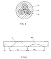
- the conductors 2 are made, as in Fig. 5 using a three-wire line is shown, from a z. B. finely stranded conductor core 2a, which is surrounded by an insulating sleeve 3.
- a plastic jacket 11 extruded On the ladder 2 will be in the jacket extrusion device 6 a plastic jacket 11 extruded, the cooled or cured in the subsequent cooling section 7 becomes.
- the SZ stranding, d. H. Stranding of ladder 2 with alternating Turning or impact direction takes place with a conventional SZ stranding machine 4, which as well known in the prior art can be constructed and therefore not described here.
- a conveyor 5 in the illustrated embodiment designed as a tape hood. Any other form of conveyor, z. B. as Scheibenzug, but is also conceivable.
- the conveyor 5 acts on the one hand as a strain relief for the Stranding in the subsequent section of the device and on the other hand as a torsion barrier, which prevents the SZ stranding after the SZ-stranding machine 4 turns up.
- a take-off device 8 is e.g. in shape a tape take-off provided by the stranded conductor 2 through the jacket extrusion device 6 and then with extruded Coat 11 passes through the cooling section 7. After the withdrawal device 8, the finished conduit 1 is transferred to the storage device 10 wound up.
- the tension measuring device 12 is between the conveyor 5 and the jacket extrusion device 6 intended.
- the tension measuring device 12 is one in the drawings not shown control with the in the drawings also not shown drive the conveyor 5 connected and controls it so that the train on the ladder 2 in this area specified upper and lower limits neither exceeds nor below.
- the Switzerland Bachmeß driving 12 has in the in Figs. 1, 2 and 4 shown Embodiments, a guide roller 13, which the stranded conductor 2 from its extended position 14 by a few degrees distracting.
- Fig. 6 is a rough schematic SZ stranding on a conductor. 2 represented by SL is the lay length, d. H. those Length at which the conductor 2 is stranded by 360 °.
- WL is the Coiled length, which represents the area in which the Slope of the conductor 2 is greater than in the range of lay length SL.
- the conductor 2 In the area of the turn length and in particular in the area around the turning point WP is the conductor 2 more stretched or parallel to Longitudinal axis 15 of the stranding, whereby one of several conductors. 2 stranded line 1 has a higher rigidity in this area, as in the area of ideal stranding next to the turning point or turn length WL with a mean lay length SL.
- the length A of the free-running Conductor sections should be equal to or shorter than the turn length WL should, since in this way prevents the stranding in the Range of the turn length WL could unintentionally turn up.
- the ratio of lay length SL to length A is in the context of Invention according to the respective requirements substantially between 1: 1 and 1: 4, but these values are in special cases can also be exceeded and especially without the To leave the scope of the present invention.
- the ratios 1: 1.5, 1: 2, 1: 2.5, 1: 3, 1: 3.5 and 1: 4 are preferred Conditions in the context of the present invention.
- the Switzerlandß healthy 12 is in one Embodiment designed as a guide roller 13, which in the direction the double arrow 16 against the force of a compression spring 17 slidably is mounted, wherein the amount of displacement of the guide roller 13th in the direction of the double arrow 16 a measure of the stranding the conductor 2 is the dominant tension. If the pulley 13 through the compression spring 17 too far in the direction of the stranding 2 (upwards in Fig. 2) shifted, the drive of the conveyor 5 is something slowed down. If the pulley 13 through the stranding 2 too far pushed back against the force of the spring 17 (down in Fig.
- the tensile force exceeds a predetermined amount and the conveying speed the conveyor 5 is increased. It is preferred that the speed at which the discharge device. 8 works, stays constant. In an amendment, but also the Speed at which the discharge device 8 operates changed and the speed of the conveyor 5 kept constant become.
- FIG. 3 shows an embodiment of a tension measuring device 12, the one stationary mounted pulley 18 and two movably mounted on a common carrier 19 mounted pulleys 20th having.
- the pulleys 20 are of the pulley 18 opposite side of the stranded conductors 2, so that the conductors 2 serpentine between the pulleys 18 and 20th be passed.
- the carrier 19 is against the force of a Spring 17 on a guide 21 substantially transverse to L Lucasserstrekkung the stranded conductor 2 slidably, the extent of Displacement in the direction of the double arrow 16 is a measure of the tensile stress in the stranded conductors 2 is.
- the free lengths A between the conveyor 5, the pulleys 18 and 20 and the jacket extrusion device 6 is thereby each below the limits defined above.
- the illustrated in Fig. 3 Embodiment is characterized as a result of the relatively large Contents in the form of relatively long, serpentine by the pulleys 18, 20 guided stranding of the conductor 2 through a particularly accurate measurement of the tensile force in the ladders 2.
- this embodiment is particularly suitable when the Distance between the conveyor 5 and the jacket extrusion device 6 is relatively large, since the length of the stranded conductor 2 is interrupted several times in this area, which again the Length A of the free-running conductor sections is limited.
- Figs. 2 and 3 can also any other form of device with which the pulleys 13 and 18 are charged against the ladder 2 out, be provided. As well also, only two or more than three pulleys can be provided be, which abut the conductors 2 from opposite sides.
- An apparatus for producing flexible electrical lines 1 made of substantially elastic conductors 2 has an SZ stranding machine 4, which the ladder 2 with a mean lay length SL stranded onto which a conveyor 5, a jacket extrusion device 6 and a discharge device 8 follow.
- a Switzerland extrusion device 6 Between the Conveyor 5 and the jacket extrusion device 6 is a Werner-on-Sunaselator (SZ stranding machine 4, which the ladder 2 with a mean lay length SL stranded onto which a conveyor 5, a jacket extrusion device 6 and a discharge device 8 follow.
- a Switzerlandß noise 12 Between the Conveyor 5 and the jacket extrusion device 6 is a Wermeß noise 12 arranged, which via a controller for speed control is connected to the conveyor 5.
- the length A of free running sections of the conductors 2 between the Conveyor 5, the Wermeß listening 12, both as Torsionssperren act, and the jacket extrusion device 6 is not greater than 4 times the mean lay length SL
Landscapes
- Engineering & Computer Science (AREA)
- Manufacturing & Machinery (AREA)
- Processes Specially Adapted For Manufacturing Cables (AREA)
- Insulated Conductors (AREA)
- Wire Processing (AREA)
- Extrusion Moulding Of Plastics Or The Like (AREA)
Claims (10)
- Dispositif de fabrication de conduites électriques souples (1) à partir de conducteurs (2) essentiellement élastiques au moyen d'une toronneuse SZ (4) qui toronne les conducteurs (2) avec un tour de cordage moyen (SL), suivi par un dispositif convoyeur (5), un dispositif d'extrusion de gaine (6) et un dispositif d'extraction (8), caractérisé en ce qu'un dispositif de mesure de la traction (12), relié par l'intermédiaire d'une commande de vitesse au dispositif convoyeur (5) et/ou au dispositif d'extraction (8), est disposé entre le dispositif convoyeur (5) et le dispositif d'extrusion de gaine (6), et en ce que la longueur (A) de tronçons courant librement des conducteurs (2) entre le dispositif convoyeur (5), le dispositif de mesure de la traction (12) et le dispositif d'extrusion de gaine (6) n'est pas supérieure au quadruple du tour de cordage moyen (SL).
- Dispositif selon la revendication 1, caractérisé en ce que la longueur (A) n'est pas supérieure au triple du tour de cordage moyen (SL).
- Dispositif selon la revendication 1, caractérisé en ce que la longueur (A) n'est pas supérieure au double du tour de cordage moyen (SL).
- Dispositif selon l'une des revendications 1 à 3, caractérisé en ce que le dispositif de mesure de la traction (12) présente au moins une poulie de renvoi (13).
- Dispositif selon l'une des revendications 1 à 4, caractérisé en ce que l'axe de la poulie de renvoi (13) est disposé stationnaire et agit sur un dispositif de mesure de force (21) qui mesure la force appliquée par les conducteurs (2) sur la poulie de renvoi (13).
- Dispositif selon l'une des revendications 1 à 5, caractérisé en ce que la poulie de renvoi (13) est déplaçable essentiellement transversalement aux conducteurs (2) à l'encontre de la force d'un ressort (17) et en ce que le chemin de déplacement de la poulie de renvoi (13) est mesuré par le dispositif de mesure.
- Dispositif selon l'une des revendications 1 à 6, caractérisé en ce que sont prévues deux poulies de renvoi ou plus qui sont adjacentes aux faces, opposées les unes aux autres, des conducteurs (2).
- Dispositif selon la revendication 7, caractérisé en ce que deux poulies de renvoi (18, 20) ou plus sont prévues, qu'une partie des poulies de renvoi (18) est logée stationnaire et que l'autre partie des poulies de renvoi (20), disposées sur un support commun (19), est déplaçable essentiellement transversalement à l'extension des conducteurs (2), à l'encontre de la force d'un ressort (17).
- Dispositif selon la revendication 8, caractérisé en ce que trois poulies de renvoi (18, 20) sont prévues, qu'une poulie de renvoi (18) est logée stationnaire et que les deux autres poulies de renvoi (20), disposées sur un support commun (19), sont déplaçables essentiellement transversalement à l'extension des conducteurs (2), à l'encontre de la force d'un ressort (17) et adjacentes à la face, opposée à la poulie stationnaire (18), des conducteurs (2).
- Dispositif selon l'une des revendications 7 à 9, caractérisé en ce que les écarts entre les poulies de renvoi (18, 20) sont réglables.
Priority Applications (1)
| Application Number | Priority Date | Filing Date | Title |
|---|---|---|---|
| AT99890035T ATE292841T1 (de) | 1998-02-20 | 1999-02-02 | Vorrichtung zum herstellen flexibler elektrischer leitungen |
Applications Claiming Priority (2)
| Application Number | Priority Date | Filing Date | Title |
|---|---|---|---|
| AT30698 | 1998-02-20 | ||
| AT0030698A AT405774B (de) | 1998-02-20 | 1998-02-20 | Vorrichtung zum herstellen flexibler, elektrischer leitungen |
Publications (3)
| Publication Number | Publication Date |
|---|---|
| EP0938103A2 EP0938103A2 (fr) | 1999-08-25 |
| EP0938103A3 EP0938103A3 (fr) | 2000-11-08 |
| EP0938103B1 true EP0938103B1 (fr) | 2005-04-06 |
Family
ID=3487065
Family Applications (1)
| Application Number | Title | Priority Date | Filing Date |
|---|---|---|---|
| EP99890035A Expired - Lifetime EP0938103B1 (fr) | 1998-02-20 | 1999-02-02 | Dispositif de fabrication de câbles électriques flexibles |
Country Status (3)
| Country | Link |
|---|---|
| EP (1) | EP0938103B1 (fr) |
| AT (2) | AT405774B (fr) |
| DE (1) | DE59911860D1 (fr) |
Families Citing this family (1)
| Publication number | Priority date | Publication date | Assignee | Title |
|---|---|---|---|---|
| ES2296461B2 (es) * | 2005-07-26 | 2008-11-01 | Universidad De Vigo | Procedimiento de prediccion y control de la capacidad de un cable de par trenzado con drenaje, apantallado con lamina de doble capa y con cubierta protectora, mediante la variacion del paso del trenzado. |
Family Cites Families (2)
| Publication number | Priority date | Publication date | Assignee | Title |
|---|---|---|---|---|
| DE2855593C2 (de) * | 1978-12-22 | 1983-12-15 | Felten & Guilleaume Energietechnik GmbH, 5000 Köln | Vorrichtung zum reversierenden Verseilen schwer verformbarer Starkstromkabeladern |
| DE19605491A1 (de) * | 1996-02-14 | 1997-08-21 | Siemens Ag | Verfahren sowie Vorrichtung zur SZ-Verseilung langgestreckter Verseilelemente |
-
1998
- 1998-02-20 AT AT0030698A patent/AT405774B/de active
-
1999
- 1999-02-02 AT AT99890035T patent/ATE292841T1/de active
- 1999-02-02 DE DE59911860T patent/DE59911860D1/de not_active Expired - Lifetime
- 1999-02-02 EP EP99890035A patent/EP0938103B1/fr not_active Expired - Lifetime
Also Published As
| Publication number | Publication date |
|---|---|
| EP0938103A3 (fr) | 2000-11-08 |
| AT405774B (de) | 1999-11-25 |
| DE59911860D1 (de) | 2005-05-12 |
| EP0938103A2 (fr) | 1999-08-25 |
| ATE292841T1 (de) | 2005-04-15 |
| ATA30698A (de) | 1999-03-15 |
Similar Documents
| Publication | Publication Date | Title |
|---|---|---|
| EP0796158B1 (fr) | Procede et dispositif de production optimisee de ressorts helicoidaux sur des machines automatiques a enrouler les ressorts | |
| DE3521485C2 (de) | Vorrichtung zur Herstellung eines verseilten, mehrdrähtigen, verdichteten Rundleiters | |
| DE3215638A1 (de) | Stahlseil zur verstaerkung von elastomermaterial | |
| DE2320690A1 (de) | Verfahren und vorrichtung zur bewicklung von elektrospulen | |
| DE2918713C2 (fr) | ||
| EP0007473B1 (fr) | Dispositif de câblage SZ d'âmes de câbles de courant fort avec une section transversale du conducteur en forme d'un secteur | |
| DE69203179T2 (de) | Reversierende Verseilvorrichtung. | |
| EP3419773A1 (fr) | Installation de fabrication, pourvue d'un organe de transport à aimants permanents, pour façonner un matériau en fil enroulé sous forme de bobine de fil | |
| DE69311103T2 (de) | Verfahren und Vorrichtung zum reversierenden Verseilen | |
| DE2812100C2 (de) | Verfahren zum Führen eines aus Einzelsträngen zusammengesetzten Gesamtstranges und Herstellen von gefachten Drahtspulen sowie Vorrichtung zum Durchführen des Verfahrens | |
| CH634119A5 (de) | Verfahren und vorrichtung zur kontinuierlichen herstellung von strangfoermigem gut durch verseilung von formstraengen. | |
| EP0938103B1 (fr) | Dispositif de fabrication de câbles électriques flexibles | |
| EP0793028B1 (fr) | Dispositif de réglage de la longueur d'un câble bowden pour lève-glaces | |
| DE2211111C3 (de) | Verfahren und Vorrichtung zum maschinellen Verseilen gestreckter elektrischer Einzelleiter mit unrunden Querschnitten zu einem Kabel | |
| DE102017124859A1 (de) | Verfahren zum Herstellen einer elektrischen Spule und Wickelvorrichtung | |
| DE3215986C2 (fr) | ||
| DE2412199C2 (de) | Verfahren zur abschnittsweise mit wechselnder Drallrichtung bzw. Drallänge erfolgenden Verseilung von elektrischen Kabeln oder Leitungen | |
| DE1814950C3 (de) | Universalgerüst zum Herstellen von asymmetrischen, H-förmigen Stahlprofilen | |
| DE3405693C2 (de) | Verfahren und Vorrichtung zur Nachbearbeitung von Litzen für Bowdenzüge | |
| DE69106357T2 (de) | Verfahren zur Herstellung einer Verseileinheit mit abschnittsweise wechselnder Drallrichtung. | |
| DE9210074U1 (de) | Schleppkettenersatz mit Feder | |
| DE2540788A1 (de) | Verfahren und vorrichtung zum herstellen von strangfoermigen gegenstaenden | |
| DE2112463B2 (de) | Verfahren und vorrichtung zur herstellung eines mehrdraehtigen seils | |
| EP1539389A1 (fr) | Profile compose extrude et procede d'enroulement separe de deux tubes individuels simultanement extrudes a l'aide d'un dispositif d'enroulement | |
| DE1801089C (de) | Rotierender Zwischenspeicher zur Verseilung von Verseilelementen für Kabel, insbesondere Nachrichtenkabel |
Legal Events
| Date | Code | Title | Description |
|---|---|---|---|
| PUAI | Public reference made under article 153(3) epc to a published international application that has entered the european phase |
Free format text: ORIGINAL CODE: 0009012 |
|
| AK | Designated contracting states |
Kind code of ref document: A2 Designated state(s): AT BE CH DE DK ES FI FR GB GR IT LI NL PT SE |
|
| AX | Request for extension of the european patent |
Free format text: AL;LT;LV;MK;RO;SI |
|
| PUAL | Search report despatched |
Free format text: ORIGINAL CODE: 0009013 |
|
| AK | Designated contracting states |
Kind code of ref document: A3 Designated state(s): AT BE CH CY DE DK ES FI FR GB GR IE IT LI LU MC NL PT SE |
|
| AX | Request for extension of the european patent |
Free format text: AL;LT;LV;MK;RO;SI |
|
| 17P | Request for examination filed |
Effective date: 20010502 |
|
| AKX | Designation fees paid |
Free format text: AT BE CH DE DK ES FI FR GB GR IT LI NL PT SE |
|
| GRAP | Despatch of communication of intention to grant a patent |
Free format text: ORIGINAL CODE: EPIDOSNIGR1 |
|
| GRAS | Grant fee paid |
Free format text: ORIGINAL CODE: EPIDOSNIGR3 |
|
| GRAA | (expected) grant |
Free format text: ORIGINAL CODE: 0009210 |
|
| AK | Designated contracting states |
Kind code of ref document: B1 Designated state(s): AT BE CH DE DK ES FI FR GB GR IT LI NL PT SE |
|
| PG25 | Lapsed in a contracting state [announced via postgrant information from national office to epo] |
Ref country code: NL Free format text: LAPSE BECAUSE OF FAILURE TO SUBMIT A TRANSLATION OF THE DESCRIPTION OR TO PAY THE FEE WITHIN THE PRESCRIBED TIME-LIMIT Effective date: 20050406 Ref country code: IT Free format text: LAPSE BECAUSE OF FAILURE TO SUBMIT A TRANSLATION OF THE DESCRIPTION OR TO PAY THE FEE WITHIN THE PRESCRIBED TIME-LIMIT;WARNING: LAPSES OF ITALIAN PATENTS WITH EFFECTIVE DATE BEFORE 2007 MAY HAVE OCCURRED AT ANY TIME BEFORE 2007. THE CORRECT EFFECTIVE DATE MAY BE DIFFERENT FROM THE ONE RECORDED. Effective date: 20050406 Ref country code: GB Free format text: LAPSE BECAUSE OF FAILURE TO SUBMIT A TRANSLATION OF THE DESCRIPTION OR TO PAY THE FEE WITHIN THE PRESCRIBED TIME-LIMIT Effective date: 20050406 |
|
| REG | Reference to a national code |
Ref country code: GB Ref legal event code: FG4D Free format text: NOT ENGLISH |
|
| REG | Reference to a national code |
Ref country code: CH Ref legal event code: NV Representative=s name: TROESCH SCHEIDEGGER WERNER AG Ref country code: CH Ref legal event code: EP |
|
| REF | Corresponds to: |
Ref document number: 59911860 Country of ref document: DE Date of ref document: 20050512 Kind code of ref document: P |
|
| PG25 | Lapsed in a contracting state [announced via postgrant information from national office to epo] |
Ref country code: SE Free format text: LAPSE BECAUSE OF FAILURE TO SUBMIT A TRANSLATION OF THE DESCRIPTION OR TO PAY THE FEE WITHIN THE PRESCRIBED TIME-LIMIT Effective date: 20050706 Ref country code: GR Free format text: LAPSE BECAUSE OF FAILURE TO SUBMIT A TRANSLATION OF THE DESCRIPTION OR TO PAY THE FEE WITHIN THE PRESCRIBED TIME-LIMIT Effective date: 20050706 Ref country code: DK Free format text: LAPSE BECAUSE OF FAILURE TO SUBMIT A TRANSLATION OF THE DESCRIPTION OR TO PAY THE FEE WITHIN THE PRESCRIBED TIME-LIMIT Effective date: 20050706 |
|
| PG25 | Lapsed in a contracting state [announced via postgrant information from national office to epo] |
Ref country code: ES Free format text: LAPSE BECAUSE OF FAILURE TO SUBMIT A TRANSLATION OF THE DESCRIPTION OR TO PAY THE FEE WITHIN THE PRESCRIBED TIME-LIMIT Effective date: 20050717 |
|
| PG25 | Lapsed in a contracting state [announced via postgrant information from national office to epo] |
Ref country code: PT Free format text: LAPSE BECAUSE OF FAILURE TO SUBMIT A TRANSLATION OF THE DESCRIPTION OR TO PAY THE FEE WITHIN THE PRESCRIBED TIME-LIMIT Effective date: 20050908 |
|
| NLV1 | Nl: lapsed or annulled due to failure to fulfill the requirements of art. 29p and 29m of the patents act | ||
| GBV | Gb: ep patent (uk) treated as always having been void in accordance with gb section 77(7)/1977 [no translation filed] |
Effective date: 20050406 |
|
| PLBE | No opposition filed within time limit |
Free format text: ORIGINAL CODE: 0009261 |
|
| STAA | Information on the status of an ep patent application or granted ep patent |
Free format text: STATUS: NO OPPOSITION FILED WITHIN TIME LIMIT |
|
| PG25 | Lapsed in a contracting state [announced via postgrant information from national office to epo] |
Ref country code: BE Free format text: LAPSE BECAUSE OF NON-PAYMENT OF DUE FEES Effective date: 20060228 |
|
| 26N | No opposition filed |
Effective date: 20060110 |
|
| EN | Fr: translation not filed | ||
| BERE | Be: lapsed |
Owner name: ROSENDAHL MASCHINEN GMBH Effective date: 20060228 |
|
| PG25 | Lapsed in a contracting state [announced via postgrant information from national office to epo] |
Ref country code: FR Free format text: LAPSE BECAUSE OF FAILURE TO SUBMIT A TRANSLATION OF THE DESCRIPTION OR TO PAY THE FEE WITHIN THE PRESCRIBED TIME-LIMIT Effective date: 20050406 |
|
| REG | Reference to a national code |
Ref country code: DE Ref legal event code: R082 Ref document number: 59911860 Country of ref document: DE Representative=s name: PATENTANWAELTE OSTRIGA, SONNET, WIRTHS & VORWE, DE |
|
| PGFP | Annual fee paid to national office [announced via postgrant information from national office to epo] |
Ref country code: DE Payment date: 20140220 Year of fee payment: 16 Ref country code: FI Payment date: 20140219 Year of fee payment: 16 Ref country code: CH Payment date: 20140220 Year of fee payment: 16 |
|
| PGFP | Annual fee paid to national office [announced via postgrant information from national office to epo] |
Ref country code: AT Payment date: 20140219 Year of fee payment: 16 |
|
| REG | Reference to a national code |
Ref country code: DE Ref legal event code: R119 Ref document number: 59911860 Country of ref document: DE |
|
| REG | Reference to a national code |
Ref country code: CH Ref legal event code: PL |
|
| REG | Reference to a national code |
Ref country code: AT Ref legal event code: MM01 Ref document number: 292841 Country of ref document: AT Kind code of ref document: T Effective date: 20150202 |
|
| PG25 | Lapsed in a contracting state [announced via postgrant information from national office to epo] |
Ref country code: FI Free format text: LAPSE BECAUSE OF NON-PAYMENT OF DUE FEES Effective date: 20150202 Ref country code: LI Free format text: LAPSE BECAUSE OF NON-PAYMENT OF DUE FEES Effective date: 20150228 Ref country code: CH Free format text: LAPSE BECAUSE OF NON-PAYMENT OF DUE FEES Effective date: 20150228 |
|
| PG25 | Lapsed in a contracting state [announced via postgrant information from national office to epo] |
Ref country code: AT Free format text: LAPSE BECAUSE OF NON-PAYMENT OF DUE FEES Effective date: 20150202 |
|
| PG25 | Lapsed in a contracting state [announced via postgrant information from national office to epo] |
Ref country code: DE Free format text: LAPSE BECAUSE OF NON-PAYMENT OF DUE FEES Effective date: 20150901 |