EP0938117A2 - Interrupteur - Google Patents
Interrupteur Download PDFInfo
- Publication number
- EP0938117A2 EP0938117A2 EP98114459A EP98114459A EP0938117A2 EP 0938117 A2 EP0938117 A2 EP 0938117A2 EP 98114459 A EP98114459 A EP 98114459A EP 98114459 A EP98114459 A EP 98114459A EP 0938117 A2 EP0938117 A2 EP 0938117A2
- Authority
- EP
- European Patent Office
- Prior art keywords
- switch
- switching element
- connection
- temperature
- switching
- Prior art date
- Legal status (The legal status is an assumption and is not a legal conclusion. Google has not performed a legal analysis and makes no representation as to the accuracy of the status listed.)
- Granted
Links
Images

Classifications
-
- H—ELECTRICITY
- H01—ELECTRIC ELEMENTS
- H01H—ELECTRIC SWITCHES; RELAYS; SELECTORS; EMERGENCY PROTECTIVE DEVICES
- H01H37/00—Thermally-actuated switches
- H01H37/02—Details
- H01H37/32—Thermally-sensitive members
- H01H37/52—Thermally-sensitive members actuated due to deflection of bimetallic element
- H01H37/54—Thermally-sensitive members actuated due to deflection of bimetallic element wherein the bimetallic element is inherently snap acting
- H01H37/5418—Thermally-sensitive members actuated due to deflection of bimetallic element wherein the bimetallic element is inherently snap acting using cantilevered bimetallic snap elements
-
- H—ELECTRICITY
- H01—ELECTRIC ELEMENTS
- H01H—ELECTRIC SWITCHES; RELAYS; SELECTORS; EMERGENCY PROTECTIVE DEVICES
- H01H37/00—Thermally-actuated switches
- H01H37/02—Details
- H01H37/32—Thermally-sensitive members
- H01H37/52—Thermally-sensitive members actuated due to deflection of bimetallic element
- H01H37/54—Thermally-sensitive members actuated due to deflection of bimetallic element wherein the bimetallic element is inherently snap acting
- H01H2037/5445—Thermally-sensitive members actuated due to deflection of bimetallic element wherein the bimetallic element is inherently snap acting with measures for avoiding slow break of contacts during the creep phase of the snap bimetal
-
- H—ELECTRICITY
- H01—ELECTRIC ELEMENTS
- H01H—ELECTRIC SWITCHES; RELAYS; SELECTORS; EMERGENCY PROTECTIVE DEVICES
- H01H37/00—Thermally-actuated switches
- H01H37/02—Details
- H01H37/32—Thermally-sensitive members
- H01H37/52—Thermally-sensitive members actuated due to deflection of bimetallic element
- H01H37/54—Thermally-sensitive members actuated due to deflection of bimetallic element wherein the bimetallic element is inherently snap acting
- H01H2037/5463—Thermally-sensitive members actuated due to deflection of bimetallic element wherein the bimetallic element is inherently snap acting the bimetallic snap element forming part of switched circuit
-
- H—ELECTRICITY
- H01—ELECTRIC ELEMENTS
- H01H—ELECTRIC SWITCHES; RELAYS; SELECTORS; EMERGENCY PROTECTIVE DEVICES
- H01H37/00—Thermally-actuated switches
- H01H37/002—Thermally-actuated switches combined with protective means
-
- H—ELECTRICITY
- H01—ELECTRIC ELEMENTS
- H01H—ELECTRIC SWITCHES; RELAYS; SELECTORS; EMERGENCY PROTECTIVE DEVICES
- H01H37/00—Thermally-actuated switches
- H01H37/02—Details
- H01H37/32—Thermally-sensitive members
- H01H37/52—Thermally-sensitive members actuated due to deflection of bimetallic element
- H01H37/54—Thermally-sensitive members actuated due to deflection of bimetallic element wherein the bimetallic element is inherently snap acting
- H01H37/5427—Thermally-sensitive members actuated due to deflection of bimetallic element wherein the bimetallic element is inherently snap acting encapsulated in sealed miniaturised housing
Definitions
- the present invention relates to a switch with a first and at least one second external connection and one temperature dependent rear derailleur which depending on its Temperature between the two external connections is electrical conductive connection for one to be guided by the switch produces electrical current, the switching mechanism being a switching element, that its geometric shape depends on the temperature a closed and an open position changed and in its In the closed position, the current flowing through the switch leads, and includes an actuator that with the switching element is permanently electrically and mechanically connected in series.
- the known switch comprises a U-shaped bimetal element as a switching element with two legs of different lengths. On a movable contact part is attached to the long leg, that interacts with a switch-fixed counter contact that again with one of the two external connections in electrical conductive connection.
- the shorter leg of the U-shaped bimetal element is on the free end of an actuator designed as a lever arm attached that with its other end firmly to the housing is connected as well as with the other of the two external connections is in an electrically conductive connection.
- the actuator is another bimetallic element that is so on the U-shaped bimetallic element is matched that the two bimetal elements deform in opposite directions with temperature changes and thus the contact pressure between the movable contact part and the counter contact fixed to the housing.
- This switch is intended as a breaker for high currents, which leads to a strong warming of the bimetallic elements lead, which ultimately the movable contact part is lifted off the fixed counter contact. Influences of Ambient temperature are the opposite Deformation of the bimetallic elements is compensated.
- the two bimetal elements are very different geometrically are designed, they also have different long-term stabilities on, so that from time to time a readjustment would be required. However, this is not in use more possible, so that overall long-term stability and thus the functional reliability leaves something to be desired.
- Another disadvantage of this construction is that large height due to the U-shaped bimetal element.
- the known current-dependent switch is therefore structurally complex, expensive and not very reliable.
- Another current-dependent one known from EP 0 103 792 B1 Switch has a bimetal spring tongue as a switching element on, which is attached to the one external connection and to her free end carries a movable contact part that with a Counter-contact cooperates, which at the free end of an elongated Spring element is arranged, the other end on the other external connection is attached.
- the switch comes with its External connections in this way in series to an electrical device switched that the operating current of this switch through the bimetal spring tongue flows.
- the known one Switch further thermally coupled to the electrical device, so that it can follow its temperature changes.
- the bimetallic spring tongue lifts the movable one Contact from the mating contact, causing the current to flow is interrupted and the electrical device before further Heating is protected.
- Bimetal spring tongue also due to an increased current flow be brought because the bimetal spring tongue through the flowing electric current heats up.
- the electrical Properties of the bimetal spring tongue can now be coordinated with the mechanical properties as well as the transition temperature be set so that they are in their Is in the closed position, in which the operating current of the electrical device conducts when both the ambient temperature is below the switching temperature as well Operating current is below a response current. Elevated the operating current now exceeds the permissible value, the bimetal spring tongue heats up very quickly and reaches its crack temperature, whereupon it moves to its open position transforms.
- This switch offers protection against overtemperature as well as overcurrent.
- sneaking can cause that the pressure of the contact against the counter contact decreases, which creates undefined switching states.
- the closing movement can make contact during the creeping phase gradually approach the counter contact, reducing the risk of Arc can be caused.
- the bimetal rear derailleur includes one mating mating contact mounted on a spring arm and a movable contact part mounted on a bimetallic arm.
- the bimetal arm is either directly on the lower part of the housing attached or it is carried by another bimetal arm, which in turn is attached to the lower part of the housing.
- a counter bearing is assigned by which the corresponding bimetal arm Temperature changes swings.
- these are matched to each other in their switching behavior and bend if the temperature rises, possibly around the counter bearing, the movable one Contact part is moved away from the mating contact, but that is adjusted due to the spring action of the spring arm.
- the bimetal arm snaps around Embossing and, if necessary, the counter bearing, which creates the movable contact part is lifted from the counter contact that is caused by a Stop is prevented from the contact part even further consequences.
- the bimetallic arms must also be used embossments restricting the creeping phase are provided, and are also supported approximately in the middle of a counter bearing that they bend accordingly.
- Another disadvantage is the migratory counter contact, which is not only structurally complex, but also here of the required stroke undesirably increases the overall height.
- DE 21 21 802 C is another temperature-dependent switch known in which the rear derailleur comprises a spring washer, which is in the closed state of the Switch is supported with its edge on a first connection electrode and a centrically supported movable contact against presses a stationary mating contact on a second connection electrode is provided.
- the two connection electrodes form an encapsulated metallic in the known switch Housing and are electrical from each other by an insulating washer isolated.
- a bimetallic snap disc is over the movable contact put that below their switching temperature loosely inside of the known switch is, so no mechanical loads is exposed.
- the operating current of the to be protected Device only flows through the spring washer with this switch, the bimetallic snap disc is driven by the operating current not burdened.
- the creep phase of the bimetallic snap disc affects this switch much less than the ones mentioned before Switches, so that relatively inexpensive switching elements are used here that also have a long lifespan.
- the bimetallic snap disc exceeds its switching temperature is warmed out, it jumps at the end of the crawl phase suddenly from its convex to a concave shape and supports with its edge on the cover of the housing and presses over their middle area against the force of the spring washer the movable contact away from the mating contact, whereby the Circuit is interrupted.
- the switching element is a spring element comprises, whose actuating force is largely independent of temperature, and the switching element has a temperature-dependent actuating force, which is greater than the actuating force in its creeping phase of the spring element.
- the temperature-neutral spring element exercises on the bimetal element no longer hinder its deformation, it rather resembles the deformation of the bimetal element in the creeping phase through its own deformation in such a way that movable Contact part and fixed counter contact with each other in such a way stay safely in the system for a low contact resistance is taken care of, the contact pressure remains below the Switching temperature largely independent of the temperature.
- the creeping phase of the bimetallic element is therefore no longer as suppressed in the prior art, but balanced so to speak, the bimetal element can namely in the Deform creep phase almost unhindered, making the changes the geometry is balanced by the spring element that the switch remains securely closed.
- the temperature-dependent positioning force of the bimetal element chosen so that they are larger in the creeping phase is the largely temperature-independent actuating force of the Spring element, which is thus the "rigid" bimetal element only "leads".
- a big advantage of the new switch is its simple Construction, in addition to the housing-fixed counter contact is only one Bimetal element required, the spring element is temperature-neutral and therefore inexpensive. Overall, bimetal element and spring element still with respect to each other with respect to the actuating force be coordinated, but no longer also with regard to their temperature behavior, because the rear derailleur straightens yourself, so to speak. This makes it a standard spring element possible for all temperature ranges, making an essential one Rationalization effect is achieved. Through this construction a low overall height can also be realized, whereby at different switching temperatures no new individual Adjustment is required, just the bimetal element must have the same spring properties but different switching temperatures be interpreted.
- Another advantage is that tolerances and fluctuations in the switching temperature by guiding through the temperature-neutral Spring element to be balanced.
- the spring element at its first end with the first connection element and at its second end is connected to the switching element, wherein preferably by the spring element, the switching element in its Closed position with its free end against one with the second connection element connected counter contact is pressed and in its open position its free end from the mating contact takes off, which is preferably arranged switch-resistant is, preferably also the switching element on his free end carries a movable contact part that with the mating contact cooperates.
- switching element and the spring element welded to one another or firmly crimped together are connected, preferably the free end of the Switching element and the first end of the spring element on the same Side of the connection between the spring element and switching element lie.
- first external connection has a Connection electrode is connected to which the spring element with is attached to its first end, and if preferably the second outer connection connected to a second connection electrode and the rear derailleur between the first and the second Connection electrode is arranged.
- connection electrodes between which the switching mechanism is arranged in that the spring element with its first End is attached to a connecting electrode during the Mating contact is provided on the other connection electrode.
- first and the second connection electrode are held by an insulating support, wherein preferably the second connection electrode by extrusion-molding Is part of an insulating lower housing part, which is closed by the first connection electrode.
- planar electrodes can be what the prior art was previously not possible. However, this not only leads to a very low height of the new switch, plan this Areas also create a prerequisite for substrate printing, to realize series or parallel resistors with which the new switch can be given additional functions can be.
- a new switch is shown generally at 10, the is shown in schematic longitudinal section.
- the new switch 10 has a first external connection 11, which is integrally connected to a flat connecting electrode 12 is. Furthermore, a second external connection 14 is provided, which formed in one piece with a second connection electrode 15 is.
- the two connection electrodes 12, 15 are on an insulating support 16 held the two connection electrodes 12, 15 spaced parallel to each other.
- the insulating material carrier 16 is basically open on the side 1, an embodiment is shown in which the insulating material carrier 16 has a pot-shaped lower part 17 includes that around the second connection electrode 15 through Injection molding or potting is designed such that the second Connection electrode 15 an integral part of the lower housing part 17 is.
- the lower housing part 17 is by the first connection electrode 12 closed, this purpose as a cover part acts and from one indicated at 18, heat-welded Edge of the insulating material carrier 16 is held captive.
- connection electrodes 12, 15 Between the two connection electrodes 12, 15 is a temperature-dependent Rear derailleur 19 arranged a mechanical and electrical series connection from a spring element 21 and comprises a switching element 22, which is indicated by a at 23 Connection are connected.
- the switching element 22 is in the present case a bimetal element.
- the spring element 21 has a largely temperature-independent Actuating force, which is within the scope of the present invention means that the force or spring force of the spring element 21 in the range of the permissible operating temperature of the Switch 10 does not change noticeably.
- the positioning force of the bimetal element on the other hand is strongly temperature-dependent and also so large in the so-called creep phase that the spring element 21 do not hinder the deformation of the bimetallic element Pressure on that at constant temperature in this Spring system can thus exert rigid bimetal element.
- the spring element 21 is at its first end 25 in FIG. 1 attached to the right on the first connection electrode 12 and leads with its second end 26 in connection 23 to the switching element 22.
- the switching element 22 enters at its free end 27 movable contact part 28 with a switch-fixed counter contact 29 cooperates on the second connection electrode 15 is formed.
- a PTC element indicated at 31 is also provided, which is arranged electrically parallel to the switching mechanism 19.
- a current flowing through the switch 10 arrives now from the first external connection 11 into the first connection electrode 12 and from there via the spring element 21 in the Switching element 22 from which it moves via the movable contact part 28 emerges to via the mating contact 29 and the second connection electrode 15 to reach the second external connection 14. Elevated either the temperature of switch 10 or of the switching element 22 and / or of the switching element 22 flowing current, the switching element 22 gets into its still Opening position to be described in more detail, in which it is the movable Contact part 28 lifts from the counter contact 29.
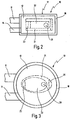
- FIG. 2 shows a top view of the switch from FIG. 1, here the first and the second external connection 11, 14 not as indicated in Fig. 1 with each other but next to each other are.
- Fig. 2 it can be seen that the edge 18 of the lower housing part 17 the first connection electrode 12 completely surrounds so that the switch 10 is completely encapsulated.
- both the spring element 21 and the switching element 22 are formed as elongated tongues are arranged one below the other in plan view are that both the first end 25 of the spring element 21st as well as the free end 27 of the switching element 22 in FIG. 2 to the right of connection 23.
- a further switch 10 is shown, which is not the square plan of Fig. 2 but a round plan having. Otherwise, the switch 10 from FIG. 3 corresponds the structure, as shown in Fig. 1 in longitudinal section, the same design features with the same reference numerals are designated. It should only be mentioned that the Spring element 21 and the switching element 22 each as an oval Discs are formed.
- the new switch 10 comprises four basic ones Components, namely the two electrodes 12, 15 and the spring element 21 and the switching element 22. All four components can punched out of tape material and for the purpose of an automatic Assembly can be merged.
- the connection 23 by welding (Fig. 1) or flanging ( Figures 4 to 6), whereupon the spring element 21 on his first end 25 is welded to the connecting electrode 12.
- the free end 27 of the switching element 22 via the mating contact 29 to lie. It should be mentioned here that of course on the movable contact part 28 can be dispensed with by the contact part 28, however, for a better contact resistance is provided to the counter contact 29.
- connection electrodes 12, 15 are then still on the Insulated support 16 attached, it being possible to the lower housing part 17 to spray around the connection electrode 15 and then the connection electrode 12 with the switching mechanism attached to it 19 to be placed from above and by a hot-pressed one Attach edge 18.
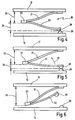
- the switching mechanism 19 from FIG. 1 is shown schematically in an enlarged view Scale shown in its closed position.
- the Switching element 22 is so far below its step temperature, that his crawl phase has not yet started.
- the switching element 22 presses against the force of the spring element 21 the connection 23 in Fig. 4 upwards, so that at 33rd indicated distance to the first connection electrode 12 and a at 34 indicated distance to the counter contact 29.
- the distance 33 increases as the distance increases 34 reduced.
- the movable contact part 28 in FIG. 5 transversely to the counter contact 29 has moved. This friction is desirable because hereby the contact surfaces between contact part 28 and Counter contact 29 cleaned, so that the electrical contact resistance is very low.
- connection 23 is still further down, the switching element 22 the movable contact part 28 is lifted from the mating contact 29 Has.
- FIGS. 4 and 6 it can be seen that that the connection 23 between the connection electrodes 12, 15 moves down while the movable contact part 28 moved in the opposite direction upwards, so that the clear Distance between the two connection electrodes 12, 15 so to speak is used twice.
- the spring element prevents 21 a contact between the connection 23 and the connection electrode 15. It should be out of elasticity considerations be necessary to design the spring element so that it press connection 23 in FIG. 6 onto connection electrode 15 would, so can between connection 23 and connection electrode 15, an insulating part can be provided, as indicated at 36 in FIG. 1 is. If in Fig. 1, the switching element 22 in its open position arrives, the spring element 21 presses the connection 23 on the insulating element 36, which is thus a contact the connecting electrode 15 prevented.
Landscapes
- Physics & Mathematics (AREA)
- Thermal Sciences (AREA)
- Thermally Actuated Switches (AREA)
- Switches With Compound Operations (AREA)
- Lock And Its Accessories (AREA)
- Push-Button Switches (AREA)
- Valve Device For Special Equipments (AREA)
- Control Of Vending Devices And Auxiliary Devices For Vending Devices (AREA)
- Percussive Tools And Related Accessories (AREA)
Priority Applications (1)
| Application Number | Priority Date | Filing Date | Title |
|---|---|---|---|
| US09/248,511 US6097274A (en) | 1998-02-23 | 1999-02-10 | Switch having a temperature-dependent switching member and a substantially temperature-independent spring element |
Applications Claiming Priority (2)
| Application Number | Priority Date | Filing Date | Title |
|---|---|---|---|
| DE19807288 | 1998-02-23 | ||
| DE19807288A DE19807288C2 (de) | 1998-02-23 | 1998-02-23 | Temperaturabhängiger Schalter |
Publications (3)
| Publication Number | Publication Date |
|---|---|
| EP0938117A2 true EP0938117A2 (fr) | 1999-08-25 |
| EP0938117A3 EP0938117A3 (fr) | 2000-07-05 |
| EP0938117B1 EP0938117B1 (fr) | 2008-10-29 |
Family
ID=7858488
Family Applications (2)
| Application Number | Title | Priority Date | Filing Date |
|---|---|---|---|
| EP98114459A Expired - Lifetime EP0938117B1 (fr) | 1998-02-23 | 1998-07-30 | Interrupteur |
| EP98115406A Expired - Lifetime EP0938116B1 (fr) | 1998-02-23 | 1998-08-17 | Interrupteur |
Family Applications After (1)
| Application Number | Title | Priority Date | Filing Date |
|---|---|---|---|
| EP98115406A Expired - Lifetime EP0938116B1 (fr) | 1998-02-23 | 1998-08-17 | Interrupteur |
Country Status (5)
| Country | Link |
|---|---|
| EP (2) | EP0938117B1 (fr) |
| AT (2) | ATE412970T1 (fr) |
| DE (3) | DE19807288C2 (fr) |
| DK (1) | DK0938117T3 (fr) |
| ES (1) | ES2316158T3 (fr) |
Families Citing this family (11)
| Publication number | Priority date | Publication date | Assignee | Title |
|---|---|---|---|---|
| DE19909059C2 (de) * | 1999-03-02 | 2003-10-16 | Marcel Hofsaes | Schalter mit Verschweißsicherung |
| DE102007042188B3 (de) | 2007-08-28 | 2009-04-09 | Hofsaess, Marcel P. | Temperaturabhängiger Schalter mit Selbsthaltefunktion |
| CN101685723B (zh) * | 2008-09-24 | 2012-04-18 | 游聪谋 | 双重温度感应断电的电路保护结构 |
| CA2812451C (fr) | 2010-09-24 | 2019-01-15 | Ellenberger & Poensgen Gmbh | Disjoncteur miniature |
| DE102014004106B4 (de) * | 2014-03-21 | 2017-02-09 | Ellenberger & Poensgen Gmbh | Thermischer Schutzschalter |
| CN111613480A (zh) * | 2020-06-25 | 2020-09-01 | 赛特勒控制器(宁波)有限公司 | 带辅助碟片的突跳式温控器 |
| CN113113264B (zh) * | 2021-03-24 | 2021-11-09 | 宁波通宝华硕温控器有限公司 | 一种小型复位温控器 |
| DE102023102301B3 (de) | 2023-01-31 | 2024-03-28 | Marcel P. HOFSAESS | Temperaturabhängiger Schalter und Verfahren zu dessen Herstellung |
| DE102023102303B3 (de) | 2023-01-31 | 2024-03-28 | Marcel P. HOFSAESS | Temperaturabhängiger Schalter |
| DE102023102302B3 (de) | 2023-01-31 | 2024-03-28 | Marcel P. HOFSAESS | Temperaturabhängiger Schalter |
| DE102023104839B3 (de) | 2023-02-28 | 2024-05-16 | Marcel P. HOFSAESS | Temperaturabhängiger Schalter |
Family Cites Families (10)
| Publication number | Priority date | Publication date | Assignee | Title |
|---|---|---|---|---|
| DE2121802C3 (de) * | 1971-05-03 | 1974-10-24 | Thermik-Geraetebau Gmbh + Co, 7530 Pforzheim | Temperaturwächter |
| US4389630A (en) * | 1980-03-15 | 1983-06-21 | Susumu Ubukatu | Snap action thermally responsive switch |
| US4319214A (en) * | 1980-07-16 | 1982-03-09 | Portage Electric Products, Inc. | Creepless, snap action thermostat |
| DE3234373A1 (de) * | 1982-09-16 | 1984-05-10 | Peter 7530 Pforzheim Hofsäss | Vorrichtung zum temperatur- und/oder stromabhaengigen schalten einer elektrischen verbindung |
| US4636766A (en) * | 1983-09-19 | 1987-01-13 | Gte Products Corporation | Miniaturized circuit breaker |
| JPH0244232U (fr) * | 1988-09-21 | 1990-03-27 | ||
| JP2519530B2 (ja) * | 1989-03-01 | 1996-07-31 | 生方 眞哉 | 熱応動スイッチ |
| US5196820A (en) * | 1990-12-19 | 1993-03-23 | Ubukata Industries Co., Ltd. | Thermally responsive switch and method of making the same |
| US5221914A (en) * | 1991-04-03 | 1993-06-22 | Ubukata Industries, Co., Ltd. | Thermally responsive switch |
| US5212465A (en) * | 1992-08-12 | 1993-05-18 | Ubukata Industries Co., Ltd. | Three-phase thermal protector |
-
1998
- 1998-02-23 DE DE19807288A patent/DE19807288C2/de not_active Expired - Fee Related
- 1998-07-30 AT AT98114459T patent/ATE412970T1/de not_active IP Right Cessation
- 1998-07-30 ES ES98114459T patent/ES2316158T3/es not_active Expired - Lifetime
- 1998-07-30 EP EP98114459A patent/EP0938117B1/fr not_active Expired - Lifetime
- 1998-07-30 DK DK98114459T patent/DK0938117T3/da active
- 1998-07-30 DE DE59814312T patent/DE59814312D1/de not_active Expired - Lifetime
- 1998-08-17 DE DE59813807T patent/DE59813807D1/de not_active Expired - Lifetime
- 1998-08-17 AT AT98115406T patent/ATE345574T1/de active
- 1998-08-17 EP EP98115406A patent/EP0938116B1/fr not_active Expired - Lifetime
Also Published As
| Publication number | Publication date |
|---|---|
| ES2316158T3 (es) | 2009-04-01 |
| DE59813807D1 (de) | 2006-12-28 |
| EP0938116A2 (fr) | 1999-08-25 |
| DE19807288C2 (de) | 2001-09-20 |
| DE19807288A1 (de) | 1999-09-09 |
| EP0938116B1 (fr) | 2006-11-15 |
| ATE412970T1 (de) | 2008-11-15 |
| ATE345574T1 (de) | 2006-12-15 |
| EP0938116A3 (fr) | 2000-05-31 |
| EP0938117B1 (fr) | 2008-10-29 |
| DE59814312D1 (de) | 2008-12-11 |
| EP0938117A3 (fr) | 2000-07-05 |
| DK0938117T3 (da) | 2009-02-16 |
Similar Documents
| Publication | Publication Date | Title |
|---|---|---|
| EP0994498B1 (fr) | Interrupteur avec support isolant | |
| DE102008048554B3 (de) | Temperaturabhängiger Schalter | |
| DE102011119633B3 (de) | Temperaturabhängiger Schalter | |
| DE102013102006B4 (de) | Temperaturabhängiger Schalter | |
| DE102011119632B3 (de) | Temperaturabhängiges Schaltwerk | |
| DE19527254C2 (de) | Temperaturwächter | |
| DE102011016896C5 (de) | Temperaturschutzschalter | |
| EP0994497B1 (fr) | Interrupteur avec support isolant | |
| EP2958125B1 (fr) | Commutateur thermodépendant doté de bague d'espacement | |
| DE102019125453A1 (de) | Temperaturabhängiger Schalter | |
| DE19609577C2 (de) | Schalter mit einem temperaturabhängigen Schaltwerk | |
| EP2783380B1 (fr) | Mécanisme interrupteur actionné thermiquement | |
| DE69414400T2 (de) | Elektrische schalter | |
| DE102009061050A1 (de) | Bimetallteil und damit ausgestattete temperaturabhängige Schalter | |
| EP0938117B1 (fr) | Interrupteur | |
| EP4411777B1 (fr) | Commutateur dépendant de la température | |
| EP3736845A1 (fr) | Commutateur dépendant de la température | |
| DE102023102301B3 (de) | Temperaturabhängiger Schalter und Verfahren zu dessen Herstellung | |
| DE102023102302B3 (de) | Temperaturabhängiger Schalter | |
| EP0778597B1 (fr) | Interrupteur avec un mécanisme de commutation actionné une température excessive | |
| DE3587064T2 (de) | Thermostat. | |
| DE2916664A1 (de) | Waermeschutzschalter | |
| DE102023104839B3 (de) | Temperaturabhängiger Schalter | |
| DE4414859C1 (de) | Thermoschalter | |
| DE102011122890A1 (de) | Temperaturabhängiges Schaltwerk |
Legal Events
| Date | Code | Title | Description |
|---|---|---|---|
| PUAI | Public reference made under article 153(3) epc to a published international application that has entered the european phase |
Free format text: ORIGINAL CODE: 0009012 |
|
| AK | Designated contracting states |
Kind code of ref document: A2 Designated state(s): AT BE CH DE DK ES FI FR GB IE IT LI NL PT SE |
|
| AX | Request for extension of the european patent |
Free format text: AL;LT;LV;MK;RO;SI |
|
| PUAL | Search report despatched |
Free format text: ORIGINAL CODE: 0009013 |
|
| AK | Designated contracting states |
Kind code of ref document: A3 Designated state(s): AT BE CH CY DE DK ES FI FR GB GR IE IT LI LU MC NL PT SE |
|
| AX | Request for extension of the european patent |
Free format text: AL;LT;LV;MK;RO;SI |
|
| 17P | Request for examination filed |
Effective date: 20001122 |
|
| AKX | Designation fees paid |
Free format text: AT BE CH DE DK ES FI FR GB IE IT LI NL PT SE |
|
| RAP1 | Party data changed (applicant data changed or rights of an application transferred) |
Owner name: HOFSAESS, MARCEL P. |
|
| RIN1 | Information on inventor provided before grant (corrected) |
Inventor name: HOFSAESS, MARCEL P. |
|
| 17Q | First examination report despatched |
Effective date: 20070928 |
|
| GRAP | Despatch of communication of intention to grant a patent |
Free format text: ORIGINAL CODE: EPIDOSNIGR1 |
|
| GRAS | Grant fee paid |
Free format text: ORIGINAL CODE: EPIDOSNIGR3 |
|
| GRAA | (expected) grant |
Free format text: ORIGINAL CODE: 0009210 |
|
| AK | Designated contracting states |
Kind code of ref document: B1 Designated state(s): AT BE CH DE DK ES FI FR GB IE IT LI NL PT SE |
|
| REG | Reference to a national code |
Ref country code: GB Ref legal event code: FG4D Free format text: NOT ENGLISH |
|
| REG | Reference to a national code |
Ref country code: CH Ref legal event code: EP |
|
| REG | Reference to a national code |
Ref country code: IE Ref legal event code: FG4D Free format text: LANGUAGE OF EP DOCUMENT: GERMAN |
|
| REF | Corresponds to: |
Ref document number: 59814312 Country of ref document: DE Date of ref document: 20081211 Kind code of ref document: P |
|
| REG | Reference to a national code |
Ref country code: CH Ref legal event code: NV Representative=s name: TROESCH SCHEIDEGGER WERNER AG |
|
| REG | Reference to a national code |
Ref country code: SE Ref legal event code: TRGR |
|
| REG | Reference to a national code |
Ref country code: DK Ref legal event code: T3 |
|
| NLV1 | Nl: lapsed or annulled due to failure to fulfill the requirements of art. 29p and 29m of the patents act | ||
| REG | Reference to a national code |
Ref country code: ES Ref legal event code: FG2A Ref document number: 2316158 Country of ref document: ES Kind code of ref document: T3 |
|
| PG25 | Lapsed in a contracting state [announced via postgrant information from national office to epo] |
Ref country code: PT Free format text: LAPSE BECAUSE OF FAILURE TO SUBMIT A TRANSLATION OF THE DESCRIPTION OR TO PAY THE FEE WITHIN THE PRESCRIBED TIME-LIMIT Effective date: 20090330 Ref country code: NL Free format text: LAPSE BECAUSE OF FAILURE TO SUBMIT A TRANSLATION OF THE DESCRIPTION OR TO PAY THE FEE WITHIN THE PRESCRIBED TIME-LIMIT Effective date: 20081029 |
|
| REG | Reference to a national code |
Ref country code: IE Ref legal event code: FD4D |
|
| PG25 | Lapsed in a contracting state [announced via postgrant information from national office to epo] |
Ref country code: IE Free format text: LAPSE BECAUSE OF FAILURE TO SUBMIT A TRANSLATION OF THE DESCRIPTION OR TO PAY THE FEE WITHIN THE PRESCRIBED TIME-LIMIT Effective date: 20081029 |
|
| PLBE | No opposition filed within time limit |
Free format text: ORIGINAL CODE: 0009261 |
|
| STAA | Information on the status of an ep patent application or granted ep patent |
Free format text: STATUS: NO OPPOSITION FILED WITHIN TIME LIMIT |
|
| 26N | No opposition filed |
Effective date: 20090730 |
|
| GBPC | Gb: european patent ceased through non-payment of renewal fee |
Effective date: 20090730 |
|
| PG25 | Lapsed in a contracting state [announced via postgrant information from national office to epo] |
Ref country code: GB Free format text: LAPSE BECAUSE OF NON-PAYMENT OF DUE FEES Effective date: 20090730 |
|
| PGFP | Annual fee paid to national office [announced via postgrant information from national office to epo] |
Ref country code: ES Payment date: 20100727 Year of fee payment: 13 Ref country code: CH Payment date: 20100726 Year of fee payment: 13 |
|
| PG25 | Lapsed in a contracting state [announced via postgrant information from national office to epo] |
Ref country code: AT Free format text: LAPSE BECAUSE OF NON-PAYMENT OF DUE FEES Effective date: 20090730 |
|
| PGFP | Annual fee paid to national office [announced via postgrant information from national office to epo] |
Ref country code: FI Payment date: 20100714 Year of fee payment: 13 |
|
| PGFP | Annual fee paid to national office [announced via postgrant information from national office to epo] |
Ref country code: BE Payment date: 20100715 Year of fee payment: 13 |
|
| PGFP | Annual fee paid to national office [announced via postgrant information from national office to epo] |
Ref country code: DK Payment date: 20110720 Year of fee payment: 14 |
|
| BERE | Be: lapsed |
Owner name: HOFSAESS, MARCEL P. Effective date: 20110731 |
|
| REG | Reference to a national code |
Ref country code: CH Ref legal event code: PL |
|
| PG25 | Lapsed in a contracting state [announced via postgrant information from national office to epo] |
Ref country code: BE Free format text: LAPSE BECAUSE OF NON-PAYMENT OF DUE FEES Effective date: 20110731 Ref country code: CH Free format text: LAPSE BECAUSE OF NON-PAYMENT OF DUE FEES Effective date: 20110731 Ref country code: LI Free format text: LAPSE BECAUSE OF NON-PAYMENT OF DUE FEES Effective date: 20110731 |
|
| PG25 | Lapsed in a contracting state [announced via postgrant information from national office to epo] |
Ref country code: FI Free format text: LAPSE BECAUSE OF NON-PAYMENT OF DUE FEES Effective date: 20110730 |
|
| REG | Reference to a national code |
Ref country code: DE Ref legal event code: R082 Ref document number: 59814312 Country of ref document: DE Representative=s name: WITTE, WELLER & PARTNER, DE |
|
| PGFP | Annual fee paid to national office [announced via postgrant information from national office to epo] |
Ref country code: SE Payment date: 20120725 Year of fee payment: 15 |
|
| REG | Reference to a national code |
Ref country code: FR Ref legal event code: CA Effective date: 20121016 |
|
| REG | Reference to a national code |
Ref country code: DE Ref legal event code: R082 Ref document number: 59814312 Country of ref document: DE Representative=s name: WITTE, WELLER & PARTNER PATENTANWAELTE MBB, DE Effective date: 20121017 Ref country code: DE Ref legal event code: R082 Ref document number: 59814312 Country of ref document: DE Representative=s name: WITTE, WELLER & PARTNER, DE Effective date: 20121017 Ref country code: DE Ref legal event code: R081 Ref document number: 59814312 Country of ref document: DE Owner name: HOFSAESS, MARCEL P., DE Free format text: FORMER OWNER: HOFSAESS, MARCEL P., 75175 PFORZHEIM, DE Effective date: 20121017 |
|
| PGFP | Annual fee paid to national office [announced via postgrant information from national office to epo] |
Ref country code: FR Payment date: 20120806 Year of fee payment: 15 |
|
| REG | Reference to a national code |
Ref country code: DK Ref legal event code: EBP |
|
| REG | Reference to a national code |
Ref country code: ES Ref legal event code: FD2A Effective date: 20130606 |
|
| PG25 | Lapsed in a contracting state [announced via postgrant information from national office to epo] |
Ref country code: DK Free format text: LAPSE BECAUSE OF NON-PAYMENT OF DUE FEES Effective date: 20120731 Ref country code: ES Free format text: LAPSE BECAUSE OF NON-PAYMENT OF DUE FEES Effective date: 20110731 |
|
| PGFP | Annual fee paid to national office [announced via postgrant information from national office to epo] |
Ref country code: IT Payment date: 20130729 Year of fee payment: 16 |
|
| REG | Reference to a national code |
Ref country code: SE Ref legal event code: EUG |
|
| REG | Reference to a national code |
Ref country code: FR Ref legal event code: ST Effective date: 20140331 |
|
| PG25 | Lapsed in a contracting state [announced via postgrant information from national office to epo] |
Ref country code: SE Free format text: LAPSE BECAUSE OF NON-PAYMENT OF DUE FEES Effective date: 20130731 |
|
| PG25 | Lapsed in a contracting state [announced via postgrant information from national office to epo] |
Ref country code: FR Free format text: LAPSE BECAUSE OF NON-PAYMENT OF DUE FEES Effective date: 20130731 |
|
| PG25 | Lapsed in a contracting state [announced via postgrant information from national office to epo] |
Ref country code: IT Free format text: LAPSE BECAUSE OF NON-PAYMENT OF DUE FEES Effective date: 20140730 |
|
| PGFP | Annual fee paid to national office [announced via postgrant information from national office to epo] |
Ref country code: DE Payment date: 20160825 Year of fee payment: 19 |
|
| REG | Reference to a national code |
Ref country code: DE Ref legal event code: R119 Ref document number: 59814312 Country of ref document: DE |
|
| PG25 | Lapsed in a contracting state [announced via postgrant information from national office to epo] |
Ref country code: DE Free format text: LAPSE BECAUSE OF NON-PAYMENT OF DUE FEES Effective date: 20180201 |