EP0938125A2 - Elektrische Entladungslampe und Verfahren zu deren Herstellung - Google Patents
Elektrische Entladungslampe und Verfahren zu deren Herstellung Download PDFInfo
- Publication number
- EP0938125A2 EP0938125A2 EP99300634A EP99300634A EP0938125A2 EP 0938125 A2 EP0938125 A2 EP 0938125A2 EP 99300634 A EP99300634 A EP 99300634A EP 99300634 A EP99300634 A EP 99300634A EP 0938125 A2 EP0938125 A2 EP 0938125A2
- Authority
- EP
- European Patent Office
- Prior art keywords
- sealing
- tube
- light
- emitting portion
- lamp
- Prior art date
- Legal status (The legal status is an assumption and is not a legal conclusion. Google has not performed a legal analysis and makes no representation as to the accuracy of the status listed.)
- Withdrawn
Links
- 238000004519 manufacturing process Methods 0.000 title claims description 5
- 238000007789 sealing Methods 0.000 claims abstract description 71
- 239000000126 substance Substances 0.000 claims abstract description 11
- 239000000945 filler Substances 0.000 claims abstract description 10
- 238000004891 communication Methods 0.000 claims description 5
- 238000004140 cleaning Methods 0.000 claims description 2
- 238000005520 cutting process Methods 0.000 claims description 2
- 239000007789 gas Substances 0.000 description 11
- 239000011521 glass Substances 0.000 description 11
- 238000000034 method Methods 0.000 description 10
- 230000004907 flux Effects 0.000 description 7
- 229910052753 mercury Inorganic materials 0.000 description 7
- QSHDDOUJBYECFT-UHFFFAOYSA-N mercury Chemical compound [Hg] QSHDDOUJBYECFT-UHFFFAOYSA-N 0.000 description 6
- 239000012535 impurity Substances 0.000 description 5
- 238000010438 heat treatment Methods 0.000 description 4
- IJGRMHOSHXDMSA-UHFFFAOYSA-N Atomic nitrogen Chemical compound N#N IJGRMHOSHXDMSA-UHFFFAOYSA-N 0.000 description 3
- 238000007796 conventional method Methods 0.000 description 3
- 229910001507 metal halide Inorganic materials 0.000 description 3
- 150000005309 metal halides Chemical class 0.000 description 3
- 238000003825 pressing Methods 0.000 description 3
- XKRFYHLGVUSROY-UHFFFAOYSA-N Argon Chemical compound [Ar] XKRFYHLGVUSROY-UHFFFAOYSA-N 0.000 description 2
- 238000010276 construction Methods 0.000 description 2
- 239000011888 foil Substances 0.000 description 2
- 230000004927 fusion Effects 0.000 description 2
- 230000003287 optical effect Effects 0.000 description 2
- 230000000717 retained effect Effects 0.000 description 2
- VYPSYNLAJGMNEJ-UHFFFAOYSA-N Silicium dioxide Chemical compound O=[Si]=O VYPSYNLAJGMNEJ-UHFFFAOYSA-N 0.000 description 1
- 229910052786 argon Inorganic materials 0.000 description 1
- 229910001873 dinitrogen Inorganic materials 0.000 description 1
- 238000001704 evaporation Methods 0.000 description 1
- 229910052736 halogen Inorganic materials 0.000 description 1
- 150000002367 halogens Chemical class 0.000 description 1
- 239000011261 inert gas Substances 0.000 description 1
- 239000007788 liquid Substances 0.000 description 1
- 239000004973 liquid crystal related substance Substances 0.000 description 1
- -1 mercury halide Chemical class 0.000 description 1
- 238000012986 modification Methods 0.000 description 1
- 230000004048 modification Effects 0.000 description 1
- 229910052757 nitrogen Inorganic materials 0.000 description 1
- 230000002093 peripheral effect Effects 0.000 description 1
- 238000012360 testing method Methods 0.000 description 1
- 238000011282 treatment Methods 0.000 description 1
- 230000000007 visual effect Effects 0.000 description 1
- 238000005406 washing Methods 0.000 description 1
Images


Classifications
-
- H—ELECTRICITY
- H01—ELECTRIC ELEMENTS
- H01J—ELECTRIC DISCHARGE TUBES OR DISCHARGE LAMPS
- H01J61/00—Gas-discharge or vapour-discharge lamps
- H01J61/02—Details
- H01J61/30—Vessels; Containers
-
- H—ELECTRICITY
- H01—ELECTRIC ELEMENTS
- H01J—ELECTRIC DISCHARGE TUBES OR DISCHARGE LAMPS
- H01J9/00—Apparatus or processes specially adapted for the manufacture, installation, removal, maintenance of electric discharge tubes, discharge lamps, or parts thereof; Recovery of material from discharge tubes or lamps
- H01J9/24—Manufacture or joining of vessels, leading-in conductors or bases
- H01J9/26—Sealing together parts of vessels
- H01J9/265—Sealing together parts of vessels specially adapted for gas-discharge tubes or lamps
Definitions
- the present invention relates to electric discharge lamps and, more particularly, to an improved sealing structure for use in such discharge lamps and a method for sealing discharge lamps.
- Discharge lamps such as extra-high pressure mercury lamps and metal halide lamps are widely used in optical instruments such as liquid crystal projectors, OHPs and motion picture projectors and in general lightings.
- Such discharge lamps are highly advantageous in that their energy efficiency is three to five times higher than that of incandescent lamps such as halogen lamps, which emit light by heating filament, and their life time is five to ten times longer than that of such incandescent lamps.
- quartz glass is shaped into a glass tube (21) having a hollow light-emitting portion (22) and sealing tubes (23) formed at opposite ends of the light-emitting portion (22). Then, a hole (24) is formed at the light-emitting portion (22) of the glass tube (25) is connected to the hole (24).
- a mount (26) having an electrode is inserted through an end of each sealing tube (23) into the glass tube (21) with use of a clamp, while nitrogen gas is introduced into the glass tube (21).
- the opposite sealing tubes (23) are then sealed by heating and pressing.
- the mount (26) is embedded in each sealing tube (23) so that the electrode is located in the light-emitting portion (22).
- a vacuum is provided in the light-emitting portion (22) through the tip tube (25), followed by required treatments such as washing.
- filer substances such as mercury or a metal halide and a rare gas are filled into the light-emitting portion (22).
- the connecting portion of the tip tube (25) is then melt and cut to seal the light-emitting portion (22), thereby providing a discharge lamp.
- a seal-cut trace (27) of the tip tube (25) remains on the light-emitting portion (22).
- the seal-cut trace hinders certain light path to cause a shadow, resulting a loss of 10 to 20 % in lighting efficiency. Accordingly, when the discharge lamp is used as the light source of a projector or the like, unevenness in the screen brightness results.
- the presence of the seal-cut trace (27) in the light-emitting portion is not preferable in terms of the strength. With the construction having such seal-cut trace, the filling gas pressure is limited, which leads to a lamp having a shorter life time.
- a first mount (36a) is inserted through an outer end of one sealing tube (33a) into a glass tube (31) as shown in Fig.3 (A).
- the sealing tube (33a) containing the first mount (36a) therein is then sealed by heating and pressing.
- filler substances such as mercury and a rare gas are introduced through an outer end (37) of another sealing tube (33b) which is not yet sealed.
- a second mount (36b) having a bent lead (35) is inserted through the outer end (37) of the sealing tube (33b).
- the outer end (37) is then sealed by the use of a laser or a plasma burner, thus closing the glass tube (31) as shown in Fig.3 (B).
- the glass tube is then taken out of the vacuum chamber and the unsealed portion (i.e., the peripheral wall embracing the second mount) of the sealing tube (33b) is sealed by heating and pressing.
- the end portion (37) is then cut away as shown in Fig.3 (C), thus completing the tipless discharge lamp.
- the seal-cut trace is not formed and , hence, the light path is not hindered. Thus the unevenness in brightness is less likely to occur. Further, since the lamp thus provided has an enhanced strength, the pressure within the light-emitting portion (32) can be greatly increased.
- the mount is retained within the glass tube by mere contact engagement between the lead (35) and the inner wall of the sealing tube (33b), the precise positioning of the electrode (36) is difficult, which leads to a poor yield.
- an electric discharge lamp comprising: a lamp envelop including a first and a second sealing tubes both of which are sealed and a light-emitting portion located between the sealing tubes; a pair of electrodes disposed in the light-emitting portion; and a filler substance encapsulated within the lamp envelop, one of the sealing tubes having a seal-cut trace of a tip tube that has been used for introducing the filler substance into the lamp envelop therethrough.
- the seal-cut trace of the tip tube is not located on the light-emitting portion, light emanates without interference by the seal-cut trace. Accordingly, the discharge lamp is less likely to suffer from a loss in the luminance and an unevenness in the brightness. Further, the light-emitting portion can be strengthened and hence, the pressure within the light-emitting portion can be increased thereby ensuring the lamp enjoying a longer life time.
- a method of making a discharge lamp comprising the steps of: providing a lamp envelop including a first and a second sealing tubes, a light-emitting portion located between the sealing tubes, and a tip tube connected to the second sealing tube for communication therbetween; inserting a first mount having a first electrode into the first sealing tube through an open end thereof so that the first electrode is located in the light-emitting portion and then entirely sealing the first sealing tube; inserting a second mount having a second electrode into the second sealing tube through an open end thereof so that the second electrode is located in the light-emitting portion and then sealing a portion of the second sealing tube so as to maintain the communication between the tip tube and the second sealing tube; cleaning the inside of the light-emitting portion an then introducing a filler substance and a rare gas through the tip tube into the light-emitting portion; removing the tip tube from the second sealing tube by sealing and cutting; and sealing the rest of the second sealing tube in which a seal
- the lamp envelop including the second sealing tube connected with the tip tube for communication therebetween is used, and accordingly, a discharge lamp is fabricated which has the seal-cut trace of the tip tube on the second sealing tube but not on the light-emitting portion. Further, since the mounts can be held firmly by clamp, the position of each electrode can be easily adjusted, which leads to a higher production yield.
- this method allows the operations of reducing the pressure in the lamp envelop and introducing the filler substance such as mercury into the lamp envelop to be easily performed through the tip tube. Hence, a large vacuum chamber is not needed. Moreover, impurities within the lamp envelop can be discharged through the tip tube and, therefore, it is possible to provide discharge lamps which avoid any failure or any shortened life time associated with such impurities.
- the presence of the seal-cut trace of the tip tube on the second sealing tube but not on the light-emitting portion enables the filling gas pressure to increase rather than the conventional level, which leads to lamps enjoying a longer life time.
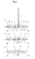
- lamp envelop (1) formed of quarts glass is first provided comprising a hollow light-emitting portion (2) at a generally central portion thereof which is substantially spherical or shaped like a rugby ball, and cylindrical sealing tubes (3a) and (3b) situated on opposite sides of the light-emitting portion (2) which are to be finally sealed to become seal portions.
- first sealing tube (3a) one of the sealing tubes
- second sealing tube (3b) one of the sealing tubes
- hole (4) is made in a portion of the second sealing tube (3b), and a tip tube (5) is connected to the hole (4) by fusion bonding as shown in Fig. 1 (A).
- first and second mounts (6a) and (6b) are inserted into the first and second sealing tubes (3a) and (3b), respectively, while N 2 gas is supplied into the lamp envelop (1).
- Each of the mounts (6a) and (6b) comprises a sealing foil (7), a lead pin (8) welded to the sealing foil (7) and an electrode (9).
- Each mount is inserted into the lamp envelop (1) while holding the lead pin (8) of the mount (6) with a clamp so that the electrode (9) is located in the light-emitting portion (9). Since each mount is firmly held by the clamp, misalignment of the electrode and shifting of the mount is not likely to occur during the manufacture of the lamp.
- the first sealing tube (3a) with the first mount (6a) inserted therein is then sealed by fusing and pinching so as to embed the first mount (6a) therein.
- the light-emitting portion (2) of the lamp envelop communicates with the outside only through the tip tube (5).
- the spacing between the two electrodes is 1.3 mm.
- the lamp envelop (1) is connected through the tip tube (5) to an evacuation device (not shown) so that the gas within the lamp envelop (1) is sucked out to reduce the pressure therein.
- Impurities generate during the sealing of the first sealing tube (3a) and the outer portion (S1) of the second sealing tube (3b) are discharged to the outside by this operation.
- the tip tube (5) After the tip tube (5) is removed from the evacuation device, predetermined amounts of mercury and a metal halide or a mercury halide, and argon gas and other inert gases are introduced through the tip tube (5) into the light-emitting portion (2). Then, the tip tube (5) is cut out by fusion to close the hole (4) as shown in Fig. 1 (B). At this time, the light-emitting portion (2) of the discharge lamp (1) is cooled with, for example, liquid nitrogen to prevent the mercury and the like encapsulated in the discharge lamp (1) from evaporating.
- Table 1 shows the comparison in brightness, while Table 2 shows the comparison in unevenness of screen brightness. Unevenness (%) of screen brightness was obtained by measuring the highest luminance and the lowest luminance of unevenness and then calculating the ratio.
- Working distance (mm) Aperture DIA (mm) Total luminous flux Prior Art No. 1 48 8 2980 2 48 8 2550 3 48 8 3120 4 48 8 2850 5 48 8 2620 average 48 8 2824 Tipless lamps No. 1 48 8 3700 2 28 8 3650 3 48 8 3700 4 48 8 3500 5 48 8 3780 average 48 8 3666 The Invention No.
- the discharge lamp in accordance with the present invention exhibits a brightness which is higher than that of the conventional discharge lamp having a seal-cut trace of a tip tube in the light emitting portion and which is substantially equal to that of the tipless discharge lamp, and is substantially freeform unevenness of brightness.
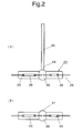
- the line C indicates the attenuation of light flux of the discharge lamp according to the present invention
- the line A indicates that of the conventional discharge lamp having a seal-cut race of a tip tube in the light emitting portion
- the line B indicates that of the tipless discharge lamp.
- the discharge lamp in accordance with the present invention exhibits less attenuation of light flux than other lamps and hence enjoys a longer life time.
- the discharge lamp in accordance with the present invention exhibits substantially the same performance as the tipless discharge lamp in brightness and evenness of brightness and enjoys a longer life time than tipless discharge lamp. Further, with the method of the present invention it is possible to provide such discharge lamps of good performance with a high yield and at a lower cost while reducing the cost for equipment.
- the present invention provides a discharge lamp which is free from unevenness of brightness, facilitates the positioning of the electrodes, enjoys a longer life time, and can be manufactured with a higher yield.
Landscapes
- Engineering & Computer Science (AREA)
- Manufacturing & Machinery (AREA)
- Vessels And Coating Films For Discharge Lamps (AREA)
- Manufacture Of Electron Tubes, Discharge Lamp Vessels, Lead-In Wires, And The Like (AREA)
Applications Claiming Priority (2)
| Application Number | Priority Date | Filing Date | Title |
|---|---|---|---|
| JP10054278A JPH11233067A (ja) | 1998-02-18 | 1998-02-18 | 放電灯及びその製造方法 |
| JP5427898 | 1998-02-18 |
Publications (2)
| Publication Number | Publication Date |
|---|---|
| EP0938125A2 true EP0938125A2 (de) | 1999-08-25 |
| EP0938125A3 EP0938125A3 (de) | 2002-01-23 |
Family
ID=12966111
Family Applications (1)
| Application Number | Title | Priority Date | Filing Date |
|---|---|---|---|
| EP99300634A Withdrawn EP0938125A3 (de) | 1998-02-18 | 1999-01-28 | Elektrische Entladungslampe und Verfahren zu deren Herstellung |
Country Status (3)
| Country | Link |
|---|---|
| US (1) | US6335593B1 (de) |
| EP (1) | EP0938125A3 (de) |
| JP (1) | JPH11233067A (de) |
Families Citing this family (2)
| Publication number | Priority date | Publication date | Assignee | Title |
|---|---|---|---|---|
| JP2001345069A (ja) * | 2000-05-31 | 2001-12-14 | Matsushita Electric Ind Co Ltd | 放電ランプおよびランプユニット、ならびにランプユニットの製造方法 |
| JP2008027698A (ja) * | 2006-07-20 | 2008-02-07 | Osram-Melco Ltd | 超高圧水銀ランプ |
Family Cites Families (7)
| Publication number | Priority date | Publication date | Assignee | Title |
|---|---|---|---|---|
| US1842624A (en) * | 1928-02-25 | 1932-01-26 | Westinghouse Lamp Co | Electron discharge tube |
| DE3029824A1 (de) * | 1980-08-06 | 1982-03-11 | Patent-Treuhand-Gesellschaft für elektrische Glühlampen mbH, 8000 München | Hochdruckentladungslampe |
| JPS57187860A (en) * | 1981-05-13 | 1982-11-18 | Hitachi Ltd | Discharge lamp with mercury of very high pressure |
| EP0093383A3 (de) * | 1982-05-03 | 1984-07-18 | Uvp, Inc. | Gasgefüllte Lampe und Verfahren zu deren Herstellung |
| US5369329A (en) * | 1992-10-09 | 1994-11-29 | Canrad, Inc. | Short arc lamp electrode rod supports |
| JP3075086B2 (ja) * | 1994-06-29 | 2000-08-07 | ウシオ電機株式会社 | 放電ランプ |
| JPH1196969A (ja) * | 1997-09-19 | 1999-04-09 | Phoenix Denki Kk | 直流点灯放電灯と該放電灯をリフレクタに装着した光源 |
-
1998
- 1998-02-18 JP JP10054278A patent/JPH11233067A/ja active Pending
-
1999
- 1999-01-28 EP EP99300634A patent/EP0938125A3/de not_active Withdrawn
- 1999-01-29 US US09/239,969 patent/US6335593B1/en not_active Expired - Fee Related
Also Published As
| Publication number | Publication date |
|---|---|
| EP0938125A3 (de) | 2002-01-23 |
| US6335593B1 (en) | 2002-01-01 |
| JPH11233067A (ja) | 1999-08-27 |
Similar Documents
| Publication | Publication Date | Title |
|---|---|---|
| EP1310984B1 (de) | Quecksilberhochdruckentladungslampe, Beleuchtungs- und Bildprojektionssystem mit einer solchen Lampe | |
| JP2001023570A (ja) | ランプの封止部構造 | |
| US6335593B1 (en) | Electric discharge lamp with an improved sealing structure improving uniformity of light output and method of making | |
| EP0903772B1 (de) | Gleichstrom-Entladungslampe und Lichtquelle mit, unmittelbar an der Enladungslampe angebrachten Reflektor | |
| US8106585B2 (en) | Manufacturing method of high-pressure discharge lamp, high-pressure discharge lamp, lamp unit using high-pressure discharge lamp, and image display apparatus using high-pressure discharge lamp | |
| US7438620B2 (en) | Arc tube of discharge lamp having electrode assemblies receiving vacuum heat treatment and method of manufacturing of arc tube | |
| JPH11238489A (ja) | ランプおよび照明装置 | |
| CN100550258C (zh) | 高强度放电灯、弧光灯管及其制造方法 | |
| JPH07235284A (ja) | 管球および照明装置 | |
| KR100697390B1 (ko) | 액정표시소자의 백라이트용 형광램프 및 그 제조방법 | |
| JP2879417B2 (ja) | 冷陰極放電管の製造方法 | |
| JPH1140057A (ja) | 低圧水銀蒸気放電灯の製造方法 | |
| CN101656190A (zh) | 荧光灯 | |
| JP3594890B2 (ja) | 高圧ランプの製造方法及び該方法にて形成された高圧ランプ | |
| JP4091473B2 (ja) | ランプの製造方法 | |
| JP3653561B2 (ja) | 多重管形蛍光ランプおよび照明装置 | |
| US4689031A (en) | Method for sealing arc discharge lamps | |
| JP3402465B2 (ja) | 放電管の製造法 | |
| JPH10340705A (ja) | 放電ランプ、この放電ランプの製造方法、この放電ランプを用いたランプユニット、およびこのランプユニットを用いた光学システム | |
| JPH0773853A (ja) | 片封じ金属蒸気放電灯 | |
| JPH09245737A (ja) | ランプ及び希ガス放電灯並びにその製造方法 | |
| JPH11191399A (ja) | 管 球 | |
| JPH10247478A (ja) | 金属蒸気放電灯 | |
| JPH03122962A (ja) | 偏平放電ランプおよびその製造方法 | |
| JP2004253141A (ja) | 冷陰極蛍光ランプ、及びその製造方法 |
Legal Events
| Date | Code | Title | Description |
|---|---|---|---|
| PUAI | Public reference made under article 153(3) epc to a published international application that has entered the european phase |
Free format text: ORIGINAL CODE: 0009012 |
|
| AK | Designated contracting states |
Kind code of ref document: A2 Designated state(s): AT BE CH CY DE DK ES FI FR GB GR IE IT LI LU MC NL PT SE Kind code of ref document: A2 Designated state(s): BE DE FR GB NL |
|
| AX | Request for extension of the european patent |
Free format text: AL;LT;LV;MK;RO;SI |
|
| PUAL | Search report despatched |
Free format text: ORIGINAL CODE: 0009013 |
|
| AK | Designated contracting states |
Kind code of ref document: A3 Designated state(s): AT BE CH CY DE DK ES FI FR GB GR IE IT LI LU MC NL PT SE |
|
| AX | Request for extension of the european patent |
Free format text: AL;LT;LV;MK;RO;SI |
|
| RIC1 | Information provided on ipc code assigned before grant |
Free format text: 7H 01J 61/30 A, 7H 01J 5/02 B, 7H 01J 9/40 B, 7H 01J 61/86 B |
|
| 17P | Request for examination filed |
Effective date: 20020701 |
|
| AKX | Designation fees paid |
Free format text: BE DE FR GB NL |
|
| 17Q | First examination report despatched |
Effective date: 20050511 |
|
| STAA | Information on the status of an ep patent application or granted ep patent |
Free format text: STATUS: THE APPLICATION IS DEEMED TO BE WITHDRAWN |
|
| 18D | Application deemed to be withdrawn |
Effective date: 20051122 |