EP0938205A2 - Optischer Multiplexer/Demultiplexer - Google Patents
Optischer Multiplexer/Demultiplexer Download PDFInfo
- Publication number
- EP0938205A2 EP0938205A2 EP99103022A EP99103022A EP0938205A2 EP 0938205 A2 EP0938205 A2 EP 0938205A2 EP 99103022 A EP99103022 A EP 99103022A EP 99103022 A EP99103022 A EP 99103022A EP 0938205 A2 EP0938205 A2 EP 0938205A2
- Authority
- EP
- European Patent Office
- Prior art keywords
- channels
- channel
- filter
- wavelength
- optical
- Prior art date
- Legal status (The legal status is an assumption and is not a legal conclusion. Google has not performed a legal analysis and makes no representation as to the accuracy of the status listed.)
- Ceased
Links
Images



Classifications
-
- H—ELECTRICITY
- H04—ELECTRIC COMMUNICATION TECHNIQUE
- H04J—MULTIPLEX COMMUNICATION
- H04J14/00—Optical multiplex systems
- H04J14/02—Wavelength-division multiplex systems
- H04J14/03—WDM arrangements
- H04J14/0307—Multiplexers; Demultiplexers
Definitions
- This invention relates generally to an optical filters and more particularly to an arrangement of optical filters for multiplexing and/or demultiplexing optical signals wherein power losses and differences in power loss different channels usually associated with such demultiplexors is substantially lessened.
- Optical systems are presently being employed in the communication of voice and video information as well as in the high-speed transmission of data. Optical communication systems are desired because of the wide bandwidth available for the information signal channels.
- WDM wavelength division multiplexing
- these channels When a number of wavelengths are multiplexed and transmitted on a single optical fiber, customarily, these channels must later be demultiplexed into separate channels or wavelengths of light. For example, it may be cost effective to transmit signals of wavelength ⁇ 1, ⁇ 2, ⁇ 3, ⁇ 4, ⁇ 5, and ⁇ 6 ( ⁇ denoting a wavelength, lambda) along a single optical fiber, however, demultiplexing means are required to separate the light into six separate channels. Of course, it is desired to perform this demultiplexing at a minimum cost and with as little signal loss as possible. Furthermore, if signal loss exists, it is important for any signal loss present on any channel to be of a similar magnitude for all channels being demultiplexed.
- WDM filters There are several technologies that can be used to construct WDM filters. For example, etalon technology, diffraction grading technology, fused biconic taper technology, and holographic filter technology.
- etalon technology diffraction grading technology
- fused biconic taper technology fused biconic taper technology
- holographic filter technology One technology that has proven to be widely useful in the telecommunications industry is dichroic filter technology. This technology offers wide channel passbands, flat channel passbands, low insertion loss, moderate isolation, low cost, high reliability and field ruggedness, high thermal stability, and moderate filter roll-off characteristics.
- a dichroic filter 300 is comprised of one or more layers of dielectric material coated onto a, for example, glass substrate 305 with lenses 310 to focus the incoming and outgoing optical signals.
- the choice of dielectric material, the number of dielectric layers coated onto the substrate, and the spacing of these layers are chosen to provide the appropriate transmissive and reflective properties for a given "target" wavelength.
- the number and spacing of the dielectric layers on the substrate 305 would be chosen to provide (1) a specified passband tolerance around ⁇ 1 and (2) the necessary isolation requirements for all other transmitted wavelengths, for example, a wavelength, ⁇ 2, transmitted by a second transmitter.
- the dichroic, or WDM, filter is constructed by placing self-focusing lenses, such as "SELFOC” lenses 310, on either side of the dielectric substrate 305.
- SELFOC self-focusing lenses
- "SELFOC” lens 310 collimates incoming light ( ⁇ 1 and ⁇ 2) at the dielectric substrate.
- Attached to the "SELFOC" lenses through an adhesive bonding process are, typically, single-mode optical fibers.
- the locations at which optical fibers attach to the "SELFOC" lenses 310 are called ports: port 1 320, port 2 325, and port 3 330.
- Connected to the ports are optical fibers 335, 340, and 345 respectively.
- all of the light (comprised of ⁇ 1 and ⁇ 2) passing through fiber 335 connected to port 1 320 is collimated by lens 310 at the dielectric substrate 305.
- the substrate Since the substrate is coated to pass wavelengths around ⁇ 1, virtually all of the light at ⁇ 1 passes through the dielectric substrate 305 and, via the second "SELFOC" lens, is focused into port 3 330, and passes away from the filter on optical fiber 345. Any other wavelength incident on the filter through port 1 320 (e.g., light of wavelength ⁇ 2) is reflected off the multi-layer substrate, focused back through the first "SELFOC" lens to port 2 325, and passes away from the filter on optical fiber 340. Likewise, the filter performs the same function for light travelling in the opposite direction.
- This signal power loss is a result of both the overall distance that the signal must travel, and, more importantly much of the power loss occurs at each GRIN lens fibre interface or port.
- channel 2 which must encounter two filter elements prior to be being moved or demultiplexed from the multiplexed signal channels undergoes less loss, than for example, channel 16 which encounters 16 filter interfaces.
- a demultiplexor separates a group of channels into individual channels losses for each channel should most importantly be minimal and it is preferable that any losses introduced by the system should be as near to equal as possible for all channels. This is not the case with conventional demultiplexor designs using a conventional arrangement of cascaded narrow band dichroic filters.
- an optical filter arrangement for demultiplexing an optical signal having a plurality of channels, said filter arrangement comprising at least two filters, at least a first optical filter for separating a group of channels into a lower and a higher wavelength group of channels, each group comprising a plurality of channels, and a second optical filter for filtering and separating from the optical signal at least one channel having a central wavelength between the lower and the higher wavelength groups of channels, the at least two filters being optically coupled to one another such that the at least a channel between the lower and higher wavelength group of channels in first removed from the optical signal by the second filter before said lower or higher wavelength groups of channels are removed by the first optical filter respectively.
- an optical demultiplexor for demultiplexing an optical signal having at least n sequential channels into a plurality of channel groupings, wherein n > 3, each channel having a different central wavelength, each of n-1 of the n channels having lower central wavelength than a subsequent sequential channel, the n th channel having a highest central wavelength and the 1 st channel having the lowest central wavelength, said demultiplexor comprising:
- an optical filter arrangement comprising a plurality of filters said filters including at least a narrow band filter and a wide band filter, the narrow band filter disposed to first filter a narrow wavelength band of light and the wide band filter disposed to subsequently filter and separate wide wavelength bands of light.
- method of demultiplexing a plurality of sequential channels from an optical signal comprising the steps of: first filtering a narrow band channel having a wavelength that is substantially in the middle of a range of wavelengths of the plurality of sequential channels to remove the narrow band channel from the plurality of sequential channels; and, subsequently separating remaining channels into two groups of channels a first group having central wavelengths below the wavelength of the narrow bad channel, and a second group having central wavelengths above the wavelength of the narrow band channel.
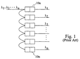
- Fig. 1 shows a cascaded prior art circuit wherein narrow band dichroic filters 10a through 10n each having a different wavelength response are serially interconnected in a cascaded arrangement to demultiplex a multiplexed optical signal comprising channels 1 to n, corresponding to wavelengths ⁇ 1, ⁇ 2, ⁇ 3, ... ⁇ n. Since there is a fixed power loss associated with each filter in transmission, and a fixed but lesser power loss associated with each filter in reflection, those signals that reflect from a plurality of filters, will be more attenuated than for example signals that reflect from one or fewer numbers of filters.
- the attenuation due to reflection of channel from n will be n-2 times greater than the attenuation due to reflection loss of channel 2.
- serially cascading filters is not preferred due to the large insertion loss for channels near the end of the series coupled filters, and furthermore, due the large differential channels loss, especially between channels at different ends of the series filters.
- Fig. 2a illustrates a cascaded demultiplexing/multiplexing optical system wherein a wide band band splitter 20 first splits 16 channels into a first group of 8 channels comprising wavelengths ⁇ 1, ⁇ 2, .... ⁇ 8, and a second group of channels comprising wavelengths ⁇ 10 ... ⁇ 16.
- the first group of channels is then presented to a first bank of cascaded filters 10a through 10h, similar to the arrangement shown if Fig. 1.
- the second group of channels is simultaneously presented to a second bank of cascaded filters 10j through 10p.
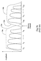
- Fig. 2b the response of the splitter 20 is shown in outline 30a and 30b. Since the splitter comprises two wide band filters, or alternatively a low and high pass filter having a less than ideal slope 32a and 32b, a channel is missed or lost, and channels on either side of the missing channel are separated into two streams as described above. The figure also illustrates how the first channel of each bank has greater amplitude than subsequent channels in that bank which are progressively attenuated.
- Fig. 4 provides circuitry wherein a single narrow band channel between two banks of channels, is first removed or demultiplexed, leaving space for wide band filters (or a high and low pass filter) to separate the channels on either side into two groups for further filtering / demultiplexing.
- a narrow band filter 10i designed to transmit a single narrow band channel, in this instance, ⁇ 9 is optically coupled with a band splitter 20 in the form of a band pass filter designed to transmit channel 1 to 8 along a straight through transmit path from port 1 to port 3 of the filter, and to reflect channels 10 to 16 along another path from port 1 to the filter element and back to port 2. Since the output response of the splitter 20 is such, that space is required between the channels being split to achieve high isolation, channel 9 having a central wavelength ⁇ 9 is first removed. In this arrangement.
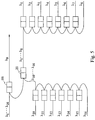
- Fig. 5 shows yet an extension to this embodiment, wherein the optical circuit of Fig. 4 is combined with the optical circuit of Fig.
- the band splitting filter could be in the form of band pass filters or high and low pass filters.
- the filters are not required to have particularly steep slopes. If however the filters are very "sloppy", i.e. if the slopes are not very steep, it may be required to provide greater isolation than is afforded by the removal of one channel, and two channels can first be removed prior to splitting blocks of channels adjacent the two channels. This can be accomplished by first passing the multiplexed signal through two narrow band filters. This is shown in Fig. 6.
- channels 32 and 33 are first dropped (or demultiplexed) by using two narrow band filters that are serially optically coupled. Subsequently, using wide band pass filters, or high and low pass filters, channels 1 to 31, and 34 to 64 are split into two groups of channels. Subsequent to providing two groups of channels, channels 1 to 31 are split in a similar fashion by using one or more narrow band filters to remove/demultiplex channel(s) 15 (and 16) and then channels 1 to 14 and 17 to 31 are separated into two sub-groups of channels.
- channels 34 to 64 can be demultiplxed by this repeated sequence of first removing one or more centrally located channels using one or more narrow band filters, and then subsequently using wide band filters or high and low pass filters to remove or demultiplex groups of channels, which can subsequently be demultiplexed using cascaded narrow band filters.
- these schemes provide a means of lessening overall signal losses by dividing long sequential chains of filters into a plurality of banks of filters.
- Bragg filter can be used for separating a channel from the group of channels.
Landscapes
- Engineering & Computer Science (AREA)
- Computer Networks & Wireless Communication (AREA)
- Signal Processing (AREA)
- Optical Communication System (AREA)
Applications Claiming Priority (2)
| Application Number | Priority Date | Filing Date | Title |
|---|---|---|---|
| US09/025,468 US5943149A (en) | 1998-02-18 | 1998-02-18 | Optical multiplexor/demultiplexor using a narrow band filter followed by a wideband filter |
| US25468 | 1998-02-18 |
Publications (2)
| Publication Number | Publication Date |
|---|---|
| EP0938205A2 true EP0938205A2 (de) | 1999-08-25 |
| EP0938205A3 EP0938205A3 (de) | 2003-11-26 |
Family
ID=21826239
Family Applications (1)
| Application Number | Title | Priority Date | Filing Date |
|---|---|---|---|
| EP99103022A Ceased EP0938205A3 (de) | 1998-02-18 | 1999-02-16 | Optischer Multiplexer/Demultiplexer |
Country Status (4)
| Country | Link |
|---|---|
| US (1) | US5943149A (de) |
| EP (1) | EP0938205A3 (de) |
| JP (1) | JPH11337765A (de) |
| CA (1) | CA2255346C (de) |
Cited By (7)
| Publication number | Priority date | Publication date | Assignee | Title |
|---|---|---|---|---|
| ES2159239A1 (es) * | 1999-06-11 | 2001-09-16 | Televisio De Catalunya S A | Sistema de transmision de fibra optica. |
| EP1185017A1 (de) * | 2000-08-30 | 2002-03-06 | Telefonaktiebolaget Lm Ericsson | Optisches Kommunikationsnetzwerk |
| US6519384B2 (en) | 2000-08-30 | 2003-02-11 | Telefonaktiebolaget Lm Ericsson (Publ) | Optical communication network |
| EP1122905A3 (de) * | 2000-02-07 | 2005-06-22 | NTT Electronics Corporation | Vorrichtung und Verfahren zum Wellenlängenmultiplexen und -demultiplexen |
| WO2005099148A1 (en) * | 2004-04-09 | 2005-10-20 | Novera Optics, Inc. | Wavelength division multiplexing passive optical network having multiple branches of optical distribution |
| WO2006125659A3 (en) * | 2005-05-26 | 2007-04-26 | Ericsson Telefon Ab L M | Optimised multiplexer/demultiplexer optical structure |
| EP2239874A1 (de) * | 2009-04-08 | 2010-10-13 | Alcatel Lucent | Vorrichtung zum Empfang von Kämmen mit Zwischenkanalfrequenzabstand |
Families Citing this family (34)
| Publication number | Priority date | Publication date | Assignee | Title |
|---|---|---|---|---|
| WO2000003277A1 (en) * | 1998-07-08 | 2000-01-20 | E-Tek Dynamics, Inc. | Improved add/drop wdm multiplexer for fiberoptic networks |
| CA2300534A1 (en) | 1999-04-13 | 2000-10-13 | Nortel Networks Corporation | Bidirectional optical networks |
| WO2000070380A1 (fr) * | 1999-05-14 | 2000-11-23 | Fujitsu Limited | Dispositif optique, appareil de station terminale et systeme de multiplexage par repartition en longueur d'onde |
| DE60028907T2 (de) * | 1999-11-24 | 2007-02-15 | Donnelly Corp., Holland | Rückspiegel mit Nutzfunktion |
| US6483618B2 (en) * | 1999-11-30 | 2002-11-19 | Corning Incorporated | Narrow band wavelength division demultiplexer and method of demultiplexing optical signals |
| US6973268B1 (en) * | 2000-06-30 | 2005-12-06 | Lucent Technologies Inc. | Bi-directional optical transmission using dual channel bands |
| JP2002090573A (ja) | 2000-07-10 | 2002-03-27 | Hoya Corp | 光フィルタモジュール及びこれを用いた各種光学装置 |
| US6944406B1 (en) | 2000-08-04 | 2005-09-13 | Fujitsu Limited | Transport system with tunable channel spacing DWDM |
| US7082267B1 (en) | 2000-08-25 | 2006-07-25 | R& Dm Foundation | Shared multi-channel parallel optical interface |
| US7099590B2 (en) * | 2000-08-25 | 2006-08-29 | R&Dm Foundation | Filtering technique for free space interconnects |
| US6731830B2 (en) | 2001-01-05 | 2004-05-04 | Redfern Broadband Networks, Inc. | Asymmetric compatible network element |
| US6452700B1 (en) | 2001-01-11 | 2002-09-17 | R&Dm Foundation | Computer backplane employing free space optical interconnect |
| US20020105696A1 (en) * | 2001-02-07 | 2002-08-08 | Ross Halgren | Transparent optical-electronic-optical switch |
| US6870976B2 (en) * | 2001-03-13 | 2005-03-22 | Opnext, Inc. | Filter based multiplexer/demultiplexer component |
| US6751373B2 (en) * | 2001-04-10 | 2004-06-15 | Gazillion Bits, Inc. | Wavelength division multiplexing with narrow band reflective filters |
| US6853812B2 (en) | 2001-05-09 | 2005-02-08 | Robert Mays, Jr. | Polarized-holographic filtering providing improved extinction ratio |
| US20020191598A1 (en) * | 2001-06-19 | 2002-12-19 | Robert Mays | Network switch employing free-space optical switching technique |
| US20020191254A1 (en) * | 2001-06-19 | 2002-12-19 | Robert Mays | Network routing employing free-space optical broadcasting |
| US6741393B1 (en) * | 2002-01-17 | 2004-05-25 | Raytheon Company | Optical system with optical frequency discriminator |
| US7340175B2 (en) * | 2002-01-18 | 2008-03-04 | Nec Corporation | Non-uniform optical waveband aggregator and deaggregator and hierarchical hybrid optical cross-connect system |
| US20030175030A1 (en) * | 2002-03-18 | 2003-09-18 | Shuqiang Chen | Re-configurable optical add/drop multiplexer module and method |
| KR20040016406A (ko) | 2002-08-15 | 2004-02-21 | 호야 가부시키가이샤 | 광 모듈 |
| US7280760B1 (en) * | 2002-08-28 | 2007-10-09 | Avanex Corporation | Upgradeable optical add/drop multiplexer |
| JP2004297714A (ja) * | 2003-03-28 | 2004-10-21 | Fujitsu Ltd | 多方向光分岐装置 |
| US20050095001A1 (en) * | 2003-10-29 | 2005-05-05 | Fujitsu Limited | Method and system for increasing network capacity in an optical network |
| US7356222B2 (en) * | 2003-11-06 | 2008-04-08 | Nippon Sheet Glass Co., Ltd. | Wavelength selective optical device and method of tuning a wavelength characteristic of the same |
| US8032024B2 (en) * | 2003-12-12 | 2011-10-04 | Alcatel Lucent | Method and apparatus for multi-band optical switching using multi-pump parametric devices |
| CN100495096C (zh) * | 2004-05-26 | 2009-06-03 | Hoya株式会社 | 光模块和光波长合波分波装置 |
| CN100488071C (zh) * | 2006-10-27 | 2009-05-13 | 华为技术有限公司 | 一种对光电集成设备进行保护的方法和光电集成设备 |
| US20160164625A1 (en) * | 2013-07-16 | 2016-06-09 | Commscope Technologies Llc | Distributed wave division multiplexing systems |
| US10162115B2 (en) * | 2014-10-16 | 2018-12-25 | Alliance Fiber Optic Products, Inc. | High isolation and high return loss 2-port optical retro-reflector |
| KR102284163B1 (ko) * | 2018-09-21 | 2021-07-30 | 주식회사 옵티코어 | 조밀 파장분할다중화를 위한 광합파 및 광분파 장치(DeMUX) |
| KR102426671B1 (ko) * | 2020-05-14 | 2022-07-29 | 주식회사 론텍 | 다양한 싱글밴드 cwdm 패스 필터를 이용하여 구현된 듀얼 밴드 cwdm 패스 필터 모듈 |
| CN113866895B (zh) * | 2020-06-30 | 2023-01-03 | 中国移动通信有限公司研究院 | 一种波分复用结构 |
Family Cites Families (3)
| Publication number | Priority date | Publication date | Assignee | Title |
|---|---|---|---|---|
| WO1996019743A1 (en) * | 1994-12-21 | 1996-06-27 | E-Tek Dynamics, Inc. | Integrable fiberoptic coupler and resulting devices and systems |
| EP0850430A1 (de) * | 1995-08-29 | 1998-07-01 | Orroyo Optics Inc. | Wellenlängenselektive optische gitter-koppler |
| US5629995A (en) * | 1996-02-01 | 1997-05-13 | Jds Fitel Inc. | Wavelength filter arrangements for use in fiber optics |
-
1998
- 1998-02-18 US US09/025,468 patent/US5943149A/en not_active Expired - Lifetime
- 1998-12-09 CA CA002255346A patent/CA2255346C/en not_active Expired - Lifetime
-
1999
- 1999-02-16 EP EP99103022A patent/EP0938205A3/de not_active Ceased
- 1999-02-17 JP JP11038437A patent/JPH11337765A/ja active Pending
Cited By (10)
| Publication number | Priority date | Publication date | Assignee | Title |
|---|---|---|---|---|
| ES2159239A1 (es) * | 1999-06-11 | 2001-09-16 | Televisio De Catalunya S A | Sistema de transmision de fibra optica. |
| EP1122905A3 (de) * | 2000-02-07 | 2005-06-22 | NTT Electronics Corporation | Vorrichtung und Verfahren zum Wellenlängenmultiplexen und -demultiplexen |
| EP1185017A1 (de) * | 2000-08-30 | 2002-03-06 | Telefonaktiebolaget Lm Ericsson | Optisches Kommunikationsnetzwerk |
| WO2002019588A1 (en) * | 2000-08-30 | 2002-03-07 | Telefonaktiebolaget L.M. Ericsson | An optical communication network |
| US6519384B2 (en) | 2000-08-30 | 2003-02-11 | Telefonaktiebolaget Lm Ericsson (Publ) | Optical communication network |
| WO2005099148A1 (en) * | 2004-04-09 | 2005-10-20 | Novera Optics, Inc. | Wavelength division multiplexing passive optical network having multiple branches of optical distribution |
| US8428460B2 (en) | 2004-04-09 | 2013-04-23 | Lg-Nortel Co., Ltd. | Wavelength division multiplexing passive optical network having multiple branches of optical distribution |
| WO2006125659A3 (en) * | 2005-05-26 | 2007-04-26 | Ericsson Telefon Ab L M | Optimised multiplexer/demultiplexer optical structure |
| US8594504B2 (en) | 2005-05-26 | 2013-11-26 | Telefonaktiebolaget L M Ericsson (Publ) | Optimised multiplexer/demultiplexer optical structure |
| EP2239874A1 (de) * | 2009-04-08 | 2010-10-13 | Alcatel Lucent | Vorrichtung zum Empfang von Kämmen mit Zwischenkanalfrequenzabstand |
Also Published As
| Publication number | Publication date |
|---|---|
| CA2255346C (en) | 2001-11-13 |
| CA2255346A1 (en) | 1999-08-18 |
| US5943149A (en) | 1999-08-24 |
| EP0938205A3 (de) | 2003-11-26 |
| JPH11337765A (ja) | 1999-12-10 |
Similar Documents
| Publication | Publication Date | Title |
|---|---|---|
| US5943149A (en) | Optical multiplexor/demultiplexor using a narrow band filter followed by a wideband filter | |
| US5608825A (en) | Multi-wavelength filtering device using optical fiber Bragg grating | |
| US5771112A (en) | Reconfigurable device for insertion-extraction of wavelengths | |
| US5629995A (en) | Wavelength filter arrangements for use in fiber optics | |
| US6754411B2 (en) | Mach-zehnder based filter demultiplexers and method | |
| US6041152A (en) | Multi-channel fiber optic communications system and multiplexer/demultiplexer arrangement therefor | |
| US6256433B1 (en) | Expandable interleaving optical add/drop filter module | |
| US5909295A (en) | Hybrid bi-directional wavelength division multiplexing device | |
| US6055347A (en) | Multi-pass optical filter | |
| US6201907B1 (en) | Optical drop circuit having group delay compensation | |
| US5978114A (en) | Modular cascaded Mach-Zehnder DWDM components | |
| US5754718A (en) | Hybrid optical filtering circuit | |
| US20020150329A1 (en) | Multi-channel wavelength division multiplexer/demultiplexer | |
| US20020131683A1 (en) | Planar lightwave wavelength blocker devices using micromachines | |
| EP1415423A1 (de) | Optischer demultiplexer | |
| US6516112B1 (en) | Optical wavelength filter and demultiplexer | |
| WO2003079559A2 (en) | Tunable dwdm demultiplexer | |
| US6546166B1 (en) | Multi-stage optical DWDM channel group interleaver | |
| EP1109342A2 (de) | Optische Demultiplexierung/Multiplexierungsvorrichtung | |
| JP4278628B2 (ja) | 光伝送システム | |
| EP1407567B1 (de) | Optische filterung durch verwendung eines add/drop-knotens | |
| JP2003185876A (ja) | 波長多重化器及び波長多重化装置 | |
| US7418168B2 (en) | Optical add/drop module | |
| KR100518382B1 (ko) | 반사체를 이용하여 높은 파장 분리비를 갖게 한 파장 가감소자 | |
| CN2404134Y (zh) | 单元式可扩充光分插复用器 |
Legal Events
| Date | Code | Title | Description |
|---|---|---|---|
| PUAI | Public reference made under article 153(3) epc to a published international application that has entered the european phase |
Free format text: ORIGINAL CODE: 0009012 |
|
| AK | Designated contracting states |
Kind code of ref document: A2 Designated state(s): AT BE CH CY DE DK ES FI FR GB GR IE IT LI LU MC NL PT SE |
|
| AX | Request for extension of the european patent |
Free format text: AL;LT;LV;MK;RO;SI |
|
| PUAL | Search report despatched |
Free format text: ORIGINAL CODE: 0009013 |
|
| AK | Designated contracting states |
Kind code of ref document: A3 Designated state(s): AT BE CH CY DE DK ES FI FR GB GR IE IT LI LU MC NL PT SE |
|
| AX | Request for extension of the european patent |
Extension state: AL LT LV MK RO SI |
|
| 17P | Request for examination filed |
Effective date: 20040329 |
|
| AKX | Designation fees paid |
Designated state(s): DE FR GB |
|
| 17Q | First examination report despatched |
Effective date: 20050506 |
|
| 17Q | First examination report despatched |
Effective date: 20050506 |
|
| RAP1 | Party data changed (applicant data changed or rights of an application transferred) |
Owner name: JDS UNIPHASE INC. |
|
| STAA | Information on the status of an ep patent application or granted ep patent |
Free format text: STATUS: THE APPLICATION HAS BEEN REFUSED |
|
| 18R | Application refused |
Effective date: 20100228 |