EP0938637B1 - Klimaanlage - Google Patents
Klimaanlage Download PDFInfo
- Publication number
- EP0938637B1 EP0938637B1 EP98940574A EP98940574A EP0938637B1 EP 0938637 B1 EP0938637 B1 EP 0938637B1 EP 98940574 A EP98940574 A EP 98940574A EP 98940574 A EP98940574 A EP 98940574A EP 0938637 B1 EP0938637 B1 EP 0938637B1
- Authority
- EP
- European Patent Office
- Prior art keywords
- heat exchanger
- securing
- plate
- air cleaner
- air conditioner
- Prior art date
- Legal status (The legal status is an assumption and is not a legal conclusion. Google has not performed a legal analysis and makes no representation as to the accuracy of the status listed.)
- Expired - Lifetime
Links
- 239000002184 metal Substances 0.000 claims description 4
- 229910052751 metal Inorganic materials 0.000 claims description 4
- 239000000428 dust Substances 0.000 description 12
- 210000000078 claw Anatomy 0.000 description 9
- 230000001143 conditioned effect Effects 0.000 description 8
- 238000004873 anchoring Methods 0.000 description 6
- 230000001877 deodorizing effect Effects 0.000 description 6
- 238000012423 maintenance Methods 0.000 description 5
- XEEYBQQBJWHFJM-UHFFFAOYSA-N Iron Chemical compound [Fe] XEEYBQQBJWHFJM-UHFFFAOYSA-N 0.000 description 4
- 229910000831 Steel Inorganic materials 0.000 description 2
- 238000005452 bending Methods 0.000 description 2
- 229910052742 iron Inorganic materials 0.000 description 2
- 239000010959 steel Substances 0.000 description 2
- XLYOFNOQVPJJNP-UHFFFAOYSA-N water Substances O XLYOFNOQVPJJNP-UHFFFAOYSA-N 0.000 description 2
- 238000010586 diagram Methods 0.000 description 1
- 230000000694 effects Effects 0.000 description 1
- 230000001747 exhibiting effect Effects 0.000 description 1
- PCHJSUWPFVWCPO-UHFFFAOYSA-N gold Chemical compound [Au] PCHJSUWPFVWCPO-UHFFFAOYSA-N 0.000 description 1
- 238000003780 insertion Methods 0.000 description 1
- 230000037431 insertion Effects 0.000 description 1
- JEIPFZHSYJVQDO-UHFFFAOYSA-N iron(III) oxide Inorganic materials O=[Fe]O[Fe]=O JEIPFZHSYJVQDO-UHFFFAOYSA-N 0.000 description 1
- 239000000463 material Substances 0.000 description 1
- 230000000717 retained effect Effects 0.000 description 1
Images



Classifications
-
- F—MECHANICAL ENGINEERING; LIGHTING; HEATING; WEAPONS; BLASTING
- F24—HEATING; RANGES; VENTILATING
- F24F—AIR-CONDITIONING; AIR-HUMIDIFICATION; VENTILATION; USE OF AIR CURRENTS FOR SCREENING
- F24F1/00—Room units for air-conditioning, e.g. separate or self-contained units or units receiving primary air from a central station
- F24F1/0007—Indoor units, e.g. fan coil units
- F24F1/0043—Indoor units, e.g. fan coil units characterised by mounting arrangements
- F24F1/0057—Indoor units, e.g. fan coil units characterised by mounting arrangements mounted in or on a wall
-
- F—MECHANICAL ENGINEERING; LIGHTING; HEATING; WEAPONS; BLASTING
- F24—HEATING; RANGES; VENTILATING
- F24F—AIR-CONDITIONING; AIR-HUMIDIFICATION; VENTILATION; USE OF AIR CURRENTS FOR SCREENING
- F24F1/00—Room units for air-conditioning, e.g. separate or self-contained units or units receiving primary air from a central station
-
- F—MECHANICAL ENGINEERING; LIGHTING; HEATING; WEAPONS; BLASTING
- F24—HEATING; RANGES; VENTILATING
- F24F—AIR-CONDITIONING; AIR-HUMIDIFICATION; VENTILATION; USE OF AIR CURRENTS FOR SCREENING
- F24F1/00—Room units for air-conditioning, e.g. separate or self-contained units or units receiving primary air from a central station
- F24F1/0007—Indoor units, e.g. fan coil units
- F24F1/0059—Indoor units, e.g. fan coil units characterised by heat exchangers
- F24F1/0063—Indoor units, e.g. fan coil units characterised by heat exchangers by the mounting or arrangement of the heat exchangers
-
- F—MECHANICAL ENGINEERING; LIGHTING; HEATING; WEAPONS; BLASTING
- F24—HEATING; RANGES; VENTILATING
- F24F—AIR-CONDITIONING; AIR-HUMIDIFICATION; VENTILATION; USE OF AIR CURRENTS FOR SCREENING
- F24F1/00—Room units for air-conditioning, e.g. separate or self-contained units or units receiving primary air from a central station
- F24F1/0007—Indoor units, e.g. fan coil units
- F24F1/0059—Indoor units, e.g. fan coil units characterised by heat exchangers
- F24F1/0067—Indoor units, e.g. fan coil units characterised by heat exchangers by the shape of the heat exchangers or of parts thereof, e.g. of their fins
-
- F—MECHANICAL ENGINEERING; LIGHTING; HEATING; WEAPONS; BLASTING
- F24—HEATING; RANGES; VENTILATING
- F24F—AIR-CONDITIONING; AIR-HUMIDIFICATION; VENTILATION; USE OF AIR CURRENTS FOR SCREENING
- F24F1/00—Room units for air-conditioning, e.g. separate or self-contained units or units receiving primary air from a central station
- F24F1/0007—Indoor units, e.g. fan coil units
- F24F1/0071—Indoor units, e.g. fan coil units with means for purifying supplied air
-
- F—MECHANICAL ENGINEERING; LIGHTING; HEATING; WEAPONS; BLASTING
- F24—HEATING; RANGES; VENTILATING
- F24F—AIR-CONDITIONING; AIR-HUMIDIFICATION; VENTILATION; USE OF AIR CURRENTS FOR SCREENING
- F24F1/00—Room units for air-conditioning, e.g. separate or self-contained units or units receiving primary air from a central station
- F24F1/0007—Indoor units, e.g. fan coil units
- F24F1/0059—Indoor units, e.g. fan coil units characterised by heat exchangers
-
- F—MECHANICAL ENGINEERING; LIGHTING; HEATING; WEAPONS; BLASTING
- F24—HEATING; RANGES; VENTILATING
- F24F—AIR-CONDITIONING; AIR-HUMIDIFICATION; VENTILATION; USE OF AIR CURRENTS FOR SCREENING
- F24F1/00—Room units for air-conditioning, e.g. separate or self-contained units or units receiving primary air from a central station
- F24F1/0007—Indoor units, e.g. fan coil units
- F24F1/0071—Indoor units, e.g. fan coil units with means for purifying supplied air
- F24F1/0076—Indoor units, e.g. fan coil units with means for purifying supplied air by electric means, e.g. ionisers or electrostatic separators
Definitions
- the present invention relates to an air conditioner incorporating an air cleaner disposed on the front surface of an upper portion of a heat exchanger, and more particularly to an improvement in a structure for mounting and securing an air cleaner.
- apparatuses each of which has a structure incorporating an indoor heat exchanger disposed in the main body of an indoor unit which is an air conditioner. Moreover, an air cleaner is provided.
- the air cleaner Since the vertical length of the air cleaner is usually shorter than that of the indoor heat exchanger, the air cleaner is disposed in the upper portion of the front surface of the indoor heat exchanger which is a surface for sucking air, the heat of which must be exchanged.
- the air cleaner is mounted by directly securing the same to an end plate of the indoor heat exchanger with screws or by inserting the same into a heat exchange pipe constituting the indoor heat exchanger, as disclosed in Japanese Patent Laid-Open No. 3-59327.
- the air cleaner is secured by screw fixing to the end plate of the indoor heat exchanger or by insertion into the heat exchange pipe.
- the indoor heat exchanger is joined to a rear plate with screws or engaged to an engaging portions provided for the rear plate so as to be secured.
- the indoor heat exchanger is usually disposed such that its upper portion is inclined rearwards, that is, the upper portion is inclined toward the rear plate.
- the air cleaner is joined to the front surface of the upper portion of the heat exchanger.
- various means such as the engagement and screw fixing, it is preferable that screw fixing is employed to firmly secure the air cleaner.
- a most usual structure is arranged such that an end of the air cleaner is secured to the end plate of the heat exchanger with screws. Since the upper portion of the heat exchanger is rearwards inclined, also the end plate of the heat exchanger is inclined. Therefore, the screws for securing the air cleaner are inserted in a direction perpendicular to the inclined end plate. That is, the screws are inserted from positions diagonally above the body of the indoor unit.
- the indoor heat exchanger is divided into a front heat exchanger section and a rear heat exchanger section.
- the foregoing sections are disposed to form an inverted V-shape in a side view.
- the front heat exchanger section is formed into a circular arc shape or folded into a multistage shape in a side view.
- the end plate has a similar shape at the two ends thereof.
- GB 2241058 discloses an air conditioner having the precharacterising features of claim 1.
- the present invention seeks to provide an air conditioner which is capable of preventing variation in the joining positions of an air cleaner and a heat exchanger occurring therein and thus enabling assembly to be completed with great accuracy.
- the present invention also seeks to provide an air cleaner exhibiting improved workability by joining the air cleaner from a uniformed direction to a front surface of an upper portion of an indoor heat exchanger having an upper portion which is rearwards inclined.
- a heat exchanger having all of the features of claim 1. Since the present invention is structured such that the securing means secures both of the heat exchanger and the air cleaner, the number of elements can be reduced. Moreover, appropriate intervals can be maintained among the heat exchanger, the air cleaner and the rear plate. Therefore, the assembling operation can be facilitated and the assembling accuracy can be improved.
- an embodiment of the present invention is structured such that the fixing screws are inserted in the same direction when the air cleaner is joined to the front surface of the upper portion of the indoor heat exchanger having the upper portion which is inclined rearwards, the workability can be improved.
- an indoor unit of an air conditioner is constituted.
- a main body 1 which is a main body of an air conditioner incorporates a front suction grille 2 which can be opened/closed; a front panel 20 provided with the front suction grille 2 and having an upper suction grille 3; and a rear plate 4, the front surface of which is closed by the front panel 20.
- an indoor heat exchanger 5 is disposed which has an inverted V-shape in a side view.
- the indoor heat exchanger 5 incorporates a front heat exchanger section 5a disposed in the front portion thereof and a rear heat exchanger section 5b disposed in the rear portion thereof.
- a sub-heat-exchanger section 5c is disposed along the upper surface of the rear heat exchanger section 5b.
- the front heat exchanger section 5a is bent into a circular arc shape in a side view.
- Each of the rear heat exchanger section 5b and the sub-heat-exchanger section 5c is formed into a linear shape in a side view.
- the upper portion of the front heat exchanger section 5a is inclined rearwards.
- Each of the heat exchanger sections 5a to 5c is a so-called fined-tube-type exchanger incorporating a plurality of fins F disposed in parallel such that small intervals are provided among the fins F; and a heat exchange pipes P which meander through the fins F and connected to one another.
- an end plate T is disposed at each of the two ends of the fins F, the end plate T having a U-shape cross sectional shape facing side and realized by a bending work.
- the end plate T has a shape corresponding to the side shape of each of the heat exchanger sections 5a to 5c.
- Each end plate T is made of a strong iron plate having an opening so that the heat exchange pipe P penetrates the opening.
- a projection 40 having a threaded hole for a securing means K to be described later is provided for a portion of the end plate T.
- the end plate T is joined and secured to the rear plate 4 by hooking or with screws so that the positions of the heat exchanger sections 5a to 5c are fixed.
- a front drain pan 6 is disposed below the front heat exchanger section 5a.
- a rear drain pan 7 is disposed below the rear heat exchanger section 5b.
- the drain pans 6 and 7 are integrally formed with the rear plate 4.
- An indoor blower having a cross-flow fan 8 is disposed between the front heat exchanger section 5a and the rear heat exchanger section 5b. Moreover, a draft duct 9 is formed between the rear plate 4 and the lower surface of the front drain pan 6.
- a blowout opening 10 is formed in the lower portion of the front panel 20.
- a plurality of wind-direction guide plates 11 are pivotally supported in the blowout opening 10.
- the upper suction grille 3 has a suction opening 3a therein.
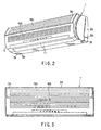
- an air cleaner 12 is disposed on the front surface of the upper portion of the front heat exchanger section 5a such that the air cleaner 12 is disposed significantly adjacently to the front heat exchanger section 5a through the securing means K.
- the upper portion of the front panel 20 projects in the widthwise direction thereof so that a projection 2a is formed.
- a first suction opening 15a is formed in the projection 2a.
- a second suction opening 15b is formed below the projection 2a.
- the air cleaner 12 incorporates an electric dust collector 13 disposed adjacently to the front heat exchanger section 5a; a deodorizing filter 14 disposed on the side of the electric dust collector 13; and a case body 50 for accommodating the electric dust collector 13 and the deodorizing filter 14.
- the electric dust collector 13 and the deodorizing filter 14 are disposed in parallel with each other and integrally accommodated in the case body 50.
- the electric dust collector 13 has a known structure incorporating a dust collecting filter and an electric discharge portion.
- the dust collecting filter and the deodorizing filter 14 are made to be detachable so as to be cleaned if necessary.
- the electric discharge portion constituted by a steel wire or a gold wire may be detachable from the case body 50 if necessary.
- the air cleaner 12 having the above-mentioned structure forwards projects over the front heat exchanger section 5a, the width of the air cleaner 12 being the same as that of the front heat exchanger section 5a.
- FIGS. 1A and 1B show a structure for joining the air cleaner 12 and the indoor heat exchanger 5 to the rear plate 4 by dint of the securing means K.
- the securing means K is constituted by a securing plate 21 which is a metal and plate-like member and which is formed by bending, for example, a steel plate; and a plurality of fixing screws 22a to 22c which are fixing members.
- the air cleaner 12 and the indoor heat exchanger 5 are integrally connected and secured to the securing plate 21. Moreover, the indoor heat exchanger 5 and the air cleaner 12 are joined and secured to the rear plate 4 through the securing plate 21.
- the securing plate 21 is disposed above the indoor heat exchanger 5. That is, the securing plate 21 is disposed from the upper portion of the front surface of the front heat exchanger section 5a, which constitutes the indoor heat exchanger 5, to the upper portion of the back side of the sub-heat-exchanger section 5c through the top end of the rear heat exchanger section 5b.
- the securing plate 21 is bent to be formed along end plates T disposed at the two ends of each of the heat exchanger sections 5a to 5c.
- the end plate T of the front heat exchanger section 5a and the securing plate 21 are joined and secured to each other by the fixing screw 22a.
- the fixing screw 22a is inserted from a diagonally upward portion.
- the rear plate 4 has an upward portion 23 inclined diagonally.
- An end 21a of the bent portion of the securing plate 21 which is placed on the end plate T on the back side of the sub-heat-exchanger section 5c is bent so that the end 21a of the bent portion is placed on the upper surface of the upward portion 23.
- the end 21a of the bent portion of the securing plate 21 and the rear plate 4 are joined and secured to each other by the fixing screw 22b.
- the fixing screw 22b is inserted from a diagonally upward position, similarly to the fixing screw 22a.
- the indoor heat exchanger 5 has the structure that the front heat exchanger section 5a and the rear heat exchanger section 5b form the inverted V-shape, a space S is necessarily formed on the back of the rear heat exchanger section 5b.
- the space S can be used as a working space for inserting/removing the fixing screw 22b between the securing plate 21 and the upward portion 23.
- an end of the securing plate 21 adjacent to the front heat exchanger section 5a is bent so as to be brought into contact with a joining flange 25 formed integrally with the air cleaner 12.
- the fixing screw 22c is used to join and secure the joining flange 25 and the end 21b of the bent portion of the securing plate 21 to each other.
- the joining flange 25 is stood erect in a substantially perpendicular direction.
- the end 21b of the bent portion of the securing plate 21 arranged to be brought into contact with the joining flange 25 is bent perpendicularly. Therefore, the fixing screw 22c for joining and securing the joining flange 25 and the end 21b of the bent portion of the securing plate 21 is inserted in a substantially horizontal direction.
- the air cleaner 12 and the indoor heat exchanger 5 are integrally connected to each other by the securing means K incorporating the securing plate 21 and the fixing screws 22a to 22c. Moreover, the air cleaner 12 and the indoor heat exchanger 5 are joined and secured to the rear plate 4 through the securing plate 21.
- the lower portion of the air cleaner 12 is positioned in close contact with the end plate T of the front heat exchanger section 5a and joined and secured to the same by a fixing screw 22d. Since the front heat exchanger section 5a has the above-mentioned shape, the fixing screw 22d is inserted in a substantially horizontal direction. As a result, each fixing screw 22d for joining and securing the upper and lower portions of the air cleaner 12 are inserted horizontally.
- claw portions 51 projecting over the case body 50 toward the front heat exchanger section 5a disposed on the rear of the case body 50 are integrally formed at another end of the air cleaner 12 in the lengthwise direction. That is, the claw portions 51 are formed at positions opposite to the direction into which the screws for securing the securing plate 21 are inserted.
- Each of the claw portions 51 has somewhat elasticity so as to be interposed and secured when the claw portions 51 are pushed from a forward position into a position between the two vertical heat exchange pipes P.
- Air introduced through the first suction opening 15a is introduced into the air cleaner 12. That is, air allowed to pass through the deodorizing filter 14 is deodorized by the deodorizing filter 14. On the other hand, fine and floating dust in air allowed to pass through the electric dust collector 13 are electrically charged in the electric charge portion so as to be captured and gathered. As a result, cleaned air is introduced into the front heat exchanger section 5a constituting the indoor heat exchanger 5 so that heat exchange is performed.
- Air sucked through the second suction opening 15b is directly introduced into the front heat exchanger section 5a so that heat exchange is performed. Air sucked through the suction opening 3a is introduced into the sub-heat-exchanger section 5c and the rear heat exchanger section 5b so that heat exchange is performed.
- Air subjected to heat exchange in the heat exchanger sections 5a to 5c is guided from the cross-flow fan 8 to the draft duct 9, and then allowed to pass through the blowout opening 10 so as to be blown out into the room which must be conditioned. Air subjected to heat exchange is circulated in the above-mentioned passage so as to be introduced into the air cleaner 12 and the indoor heat exchanger 5. Thus, air can be cleaned and conditioned as required.
- the securing means K incorporating the securing plate 21 and the fixing screws 22a to 22c integrally connect and secure both of the indoor heat exchanger 5 and the air cleaner 12 to the rear plate 4, the number of required elements can be reduced. Moreover, adequate intervals among the indoor heat exchanger 5, the air cleaner 12 and the rear plate 4 can be maintained.
- the securing plate 21 is the metal plate, satisfactory strength can be realized. If an iron plate is employed, the cost of the element can be reduced. Moreover, satisfactory durability and strength can be realized.
- the securing plate 21 Since the securing plate 21 is disposed above the indoor heat exchanger 5, drain water generated in the indoor heat exchanger 5 does not reach the securing plate 21. Therefore, generation of rust on the securing plate 21 can be prevented.
- the fixing screw 22c between the securing plate 21 and the air cleaner 12 is inserted in the substantially horizontal direction. Therefore, even if an upper working space is insufficiently small because the indoor unit is joined to the surface of a portion of a wall adjacent to the ceiling of a room which must be conditioned, removal of the air cleaner 12 from the main body 1 or joining of the same to the main body 1 can easily be performed when maintenance is performed.
- Both of the upper portion and the lower portion of the air cleaner 12 are secured to the front heat exchanger section 5a with the fixing screws 22d.
- the air cleaner 12 is secured with screws at two positions, that is the upper and lower positions. Therefore, the air cleaner 12 can firmly be joined and secured. Since the fixing screws 22c and 22d are inserted in the substantially horizontal direction, the operation for attaching/detaching the air cleaner 12 can easily be performed when maintenance is performed.
- the other end of the air cleaner 12 is arranged such that the claw portions 51 are simply inserted into a position between the heat exchange pipes P of the front heat exchanger section 5a so as to be secured. Therefore, when the fixing screw 22d which secures the end of the air cleaner 12 is removed after which the case body 50 is pulled forwards, the claw portions 51 are removed from the heat exchange pipe P. Thus, complete removal of the air cleaner 12 can significantly easily be performed.
- both of the fixing screw 22a between the end plate T of the front heat exchanger section 5a and the securing plate 21 and the fixing screw 22b between the upward portion 23 of the rear plate 4 and the securing plate 21 are inserted in the diagonally upward direction, that is, the same direction. Therefore, attachment/detachment of the securing plate 21 can easily be performed when maintenance is performed.
- the indoor heat exchanger 5 is formed into the inverted V-shape and the space S between the rear heat exchanger section 5b and the rear plate 4 is used to secure the securing plate 21 and the upward portion 23 of the rear plate 4 with the screws. Therefore, a large working space can be maintained when maintenance or the like is performed. Thus, the space S can effectively be used.
- An embodiment of the present invention has the following characteristics in addition to the securing means K.
- an opening 30 for piping is formed at each of right and left ends of the front panel 20, the right and left ends being corners between the side surface and the bottom surface of the front panel 20.
- a panel bushing 31 is received in the opening 30 for piping so that the opening 30 for piping is closed.
- FIG. 6 shows a detailed structure of the panel bushing 31.
- the panel bushing 31 is made of the same material as that of the front panel 20. Also the color and thickness of the panel bushing 31 are the same as those of the front panel 20.
- the panel bushing 31 has an L-shape.
- Slits 32 which can be knocked out if necessary, are provided for each surface.
- a hooking claw 33 projects over the leading end of each surface.
- guide members 34 are integrally formed on the two sides of the hooking claw 33.
- Each of the hooking claws 33 and the guide members 34 are detachable with respect to the ends of the piping opening 30 of the front panel 20. Therefore, the panel bushing 31 can be removed from the front panel 20, if necessary.
- sub-pipes and electric wires are drawn out from either of the right portion or the left portion of the main body 1.
- either of the sub-pipe or the electric wire may be drawn out from either of the side portion and the other element may be drawn out from the other side portion.
- the panel bushings 31 are provided for both of the right end and the left end of the front panel 20 such that removal is permitted if necessary.
- the openings 30 for piping can be opened to permit either of the right-hand piping and wiring structure and the left-hand piping and wiring structure.
- a structure for preventing looseness which is caused from a repulsion of the sub-pipe H in the indoor unit may be employed.
- the rear plate 4 is joined to an anchoring plate 35 which is previously joined to the surface of a wall of a room which must be conditioned.
- a space Sa is formed between the anchoring plate 35 and a rear portion of the lower portion of the rear plate 4.
- the sub-pipe H extending from the indoor heat exchanger, a drain hose D extending from the front drain pan 6 or an electric wire (not shown) are accommodated in parallel with one another in the space Sa.
- the outer surface of the sub-pipe H is cooled and thus the outer surface is easily frosted. Since low temperature drain water flows through the drain hose D, the outer surface of the drain hose D can easily be cooled and frosted.
- a heat insulating member 36 arranged to be bonded to the outer surface of the rear plate 4 is interposed among the sub-pipe H, the drain hose D and the rear plate 4.
- the sub-pipe H and the drain hose D are accommodated in the space Sa in the above-mentioned state, the sub-pipe H and the drain hose D are accommodated in an undesirably small space. Since the sub-pipe H is a metal pipe and the anchoring plate 35 is joined and secured to a surface W of a wall of a room which must be conditioned, repulsion of the sub-pipe H is concentrated to the lower portion of the rear plate 4. That is, the lower end of the rear plate 4 is separated from the anchoring plate 35 in the above-mentioned state. That is, looseness takes place.
- the lower end of the anchoring plate 35 is forwards bent and as well as bent rearwards in a diagonal direction so that a support flange 37 is formed.
- the lower end of the rear plate 4 is extended rearwards so that the space Sa for accommodating the sub-pipe H and the drain hose D is closed.
- An end of the extended portion is bent so that a bent member 38 which is in close contact with the support flange 37 is formed.
- the bent member 38 and the support flange 37 are connected and secured to each other by a fixing screw 22. Therefore, the fixing screw 22 firmly secures the lower end of the rear plate 4 to the lower end of the anchoring plate 35. Therefore, even if repulsion is generated from the sub-pipe H which is accommodated in the space Sa, looseness of the lower end of the rear plate 4 can be prevented.
- the lower end of the front panel 20 is extended until the lower end is brought into contact with the surface W of the wall of the room to shield the fixing screw 22.
Landscapes
- Engineering & Computer Science (AREA)
- Chemical & Material Sciences (AREA)
- Combustion & Propulsion (AREA)
- Mechanical Engineering (AREA)
- General Engineering & Computer Science (AREA)
- Physics & Mathematics (AREA)
- Thermal Sciences (AREA)
- Air Filters, Heat-Exchange Apparatuses, And Housings Of Air-Conditioning Units (AREA)
Claims (7)
- Klimaanlage, aufweisend einen Hauptkörper (1) einer Klimaanlage mit einer rückwärtigen Platte (4), einen Wärmetauscher (5), der im Hauptkörper (1) der Klimaanlage aufgenommen ist, einen Luftreiniger (12), der auf einer vorderen Oberfläche eines oberen Bereichs des Wärmetauschers (5) angeordnet ist, so dass er in dem Hauptkörper (1) der Klimaanlage aufgenommen ist, und Befestigungsmittel (21, 22a-c) zum ganzheitlichen Verbinden und Befestigen des Wärmetauschers (5) und des Luftreinigers (12) aneinander und Verbinden und Befestigen des Wärmetauschers (5) und des Luftreinigers (12) an der rückwärtigen Platte (4), dadurch gekennzeichnet, dass das Befestigungsmittel eine Befestigungsplatte (21), die ein metallenes plattenartiges Element ist, und ein Verbindungselement (22a-c) umfasst, um den Wärmetauscher (5) und den Luftreiniger (12) mit der Befestigungsplatte (21) zu verbinden und daran zu befestigen und um die Befestigungsplatte (21) mit der rückwärtigen Platte (4) zu verbinden und daran zu befestigen.
- Klimaanlage nach Anspruch 1, dadurch gekennzeichnet, dass der Wärmetauscher (5) einen oberen Abschnitt aufweist, der nach hinten geneigt ist, und
das Verbindungselement eine erste Befestigungsschraube (22c) aufweist, wobei die erste Befestigungsschraube (22c) und eine zweite Befestigungsschraube (22d) so angeordnet sind, dass sie in zwei vertikale Enden des Luftreinigers (12) im Wesentlichen parallel zueinander eingeschoben werden können, um den Luftreiniger (12) zu verbinden und zu befestigen. - Klimaanlage nach Anspruch 1, dadurch gekennzeichnet, dass das Befestigungsmittel oberhalb des Wärmetauschers angeordnet ist.
- Klimaanlage nach Anspruch 1, dadurch gekennzeichnet, dass ein oberer Bereich mindestens eines Bereichs des Wärmetauschers (5), in dem der Luftreiniger (12) angeordnet ist, nach hinten geneigt ist und
das Verbindungselement zum Verbinden und Befestigen des Luftreinigers (12) an der Befestigungsplatte (21) in einer im Wesentlichen horizontalen Richtung angeordnet ist. - Klimaanlage nach Anspruch 3, dadurch gekennzeichnet, dass der Wärmetauscher (5) eine umgekehrte V-Form aufweist, die durch einen vorderen Wärmetauscherabschnitt (5a) und einen rückwärtigen Wärmetauscherabschnitt (5b) gebildet wird, und
ein Zwischenraum im oberen Bereich auf der Rückseite des rückwärtigen Wärmetauschers (5b) verwendet wird, wenn das Befestigungsmittel den Wärmetauscher (5) und den Luftreiniger (12) mit der rückwärtigen Platte (4) verbindet und daran befestigt. - Klimaanlage nach Anspruch 5, dadurch gekennzeichnet, dass der Wärmetauscher (5) eine Anzahl an Finnen (F), die parallel zueinander angeordnet sind, und eine Endplatte (T) aufweist, die mindestens einen Bereich umfasst, der diagonal nach oben geneigt ist und der an jedem der beiden Enden der Anzahl an Finnen (F) vorhanden ist,die rückwärtige Platte (4) einen oberen Bereich aufweist, der diagonal nach oben geneigt ist,das Verbindungselement Befestigungsschrauben aufweist unddie Befestigungsschrauben (22a-22c) die Befestigungsplatte (21) und die Endplatte (T) des Wärmetauschers (5) von einer diagonal oberen Position aus verbinden und befestigen und die Befestigungsplatte (21) und den oberen Bereich der rückwärtigen Platte (4) von einer diagonal oberen Position aus sichern und befestigen.
- Klimaanlage nach Anspruch 4, dadurch gekennzeichnet, dass der Wärmetauscher (5) eine Anzahl an Finnen (F), die parallel zueinander angeordnet sind, und eine Endplatte (T) aufweist, die für jedes der beiden Enden der Anzahl an Finnen (F) vorhanden ist,
ein oberer Bereich des Luftreinigers (12) mit der Verbindungsplatte (21) verbunden und daran befestigt ist, wobei das Verbindungselement eine erste Befestigungsschraube (22c) aufweist, wobei ein unterer Bereich des Luftreinigers (12) mit der Endplatte (T) des Wärmetauschers (5) mit einer zweiten Befestigungsschraube (22d) verbunden und daran befestigt ist, und die Befestigungsschrauben (22c, 22d) zum Verbinden und Befestigen der oberen und unteren Bereiche des Luftreinigers (12) in horizontaler Richtung angeordnet sind.
Applications Claiming Priority (3)
| Application Number | Priority Date | Filing Date | Title |
|---|---|---|---|
| JP23511997 | 1997-08-29 | ||
| JP23511997A JP3676547B2 (ja) | 1997-08-29 | 1997-08-29 | 空気調和機 |
| PCT/JP1998/003810 WO1999011983A1 (en) | 1997-08-29 | 1998-08-27 | Air conditioner |
Publications (2)
| Publication Number | Publication Date |
|---|---|
| EP0938637A1 EP0938637A1 (de) | 1999-09-01 |
| EP0938637B1 true EP0938637B1 (de) | 2003-01-02 |
Family
ID=16981344
Family Applications (1)
| Application Number | Title | Priority Date | Filing Date |
|---|---|---|---|
| EP98940574A Expired - Lifetime EP0938637B1 (de) | 1997-08-29 | 1998-08-27 | Klimaanlage |
Country Status (5)
| Country | Link |
|---|---|
| EP (1) | EP0938637B1 (de) |
| JP (1) | JP3676547B2 (de) |
| KR (1) | KR100316455B1 (de) |
| CN (1) | CN1143089C (de) |
| WO (1) | WO1999011983A1 (de) |
Cited By (1)
| Publication number | Priority date | Publication date | Assignee | Title |
|---|---|---|---|---|
| EP1795821A4 (de) * | 2004-09-13 | 2010-05-19 | Daikin Ind Ltd | Innenraumeinheit einer klimaanlage |
Families Citing this family (10)
| Publication number | Priority date | Publication date | Assignee | Title |
|---|---|---|---|---|
| TW449654B (en) * | 1999-08-25 | 2001-08-11 | Fujitsu General Ltd | Air conditioner |
| JP4010327B2 (ja) * | 2005-10-31 | 2007-11-21 | ダイキン工業株式会社 | 空気調和機の室内機 |
| JP4527659B2 (ja) * | 2005-12-28 | 2010-08-18 | 三菱電機株式会社 | 空気調和機 |
| JP5316500B2 (ja) * | 2010-09-03 | 2013-10-16 | ダイキン工業株式会社 | 空気調和機の室内機 |
| CN203489362U (zh) * | 2012-06-25 | 2014-03-19 | 三菱电机株式会社 | 空调机 |
| JP6195433B2 (ja) * | 2012-10-05 | 2017-09-13 | 三菱重工サーマルシステムズ株式会社 | 空気調和機の室内ユニット |
| KR102296771B1 (ko) * | 2017-03-31 | 2021-09-02 | 엘지전자 주식회사 | 공기 조화기의 실내기 |
| CN107461905B (zh) * | 2017-07-25 | 2021-01-05 | 青岛海尔空调电子有限公司 | 用于空调器的箱盖安装结构 |
| WO2020203987A1 (ja) * | 2019-04-05 | 2020-10-08 | ダイキン工業株式会社 | 空気調和機の室内機 |
| CN113339931B (zh) * | 2021-04-26 | 2024-06-11 | 佛山市科蓝环保科技股份有限公司 | 一种空气净化器外壳及其一体加工成型的方法 |
Family Cites Families (4)
| Publication number | Priority date | Publication date | Assignee | Title |
|---|---|---|---|---|
| JPH0694011B2 (ja) * | 1988-12-20 | 1994-11-24 | 株式会社東芝 | 空気清浄装置 |
| JP2846664B2 (ja) | 1989-07-26 | 1999-01-13 | 三洋電機株式会社 | 空気調和機 |
| JPH03236525A (ja) * | 1990-02-14 | 1991-10-22 | Toshiba Corp | 空気清浄機能付き空気調和機 |
| JP3155775B2 (ja) * | 1991-07-19 | 2001-04-16 | 東芝キヤリア株式会社 | 電気集塵機 |
-
1997
- 1997-08-29 JP JP23511997A patent/JP3676547B2/ja not_active Expired - Fee Related
-
1998
- 1998-08-27 WO PCT/JP1998/003810 patent/WO1999011983A1/en not_active Ceased
- 1998-08-27 CN CNB988016168A patent/CN1143089C/zh not_active Expired - Fee Related
- 1998-08-27 EP EP98940574A patent/EP0938637B1/de not_active Expired - Lifetime
- 1998-08-27 KR KR1019997003705A patent/KR100316455B1/ko not_active Expired - Fee Related
Cited By (2)
| Publication number | Priority date | Publication date | Assignee | Title |
|---|---|---|---|---|
| EP1795821A4 (de) * | 2004-09-13 | 2010-05-19 | Daikin Ind Ltd | Innenraumeinheit einer klimaanlage |
| US7895857B2 (en) | 2004-09-13 | 2011-03-01 | Daikin Industies, Ltd. | Indoor unit of an air conditioner |
Also Published As
| Publication number | Publication date |
|---|---|
| CN1143089C (zh) | 2004-03-24 |
| EP0938637A1 (de) | 1999-09-01 |
| CN1242832A (zh) | 2000-01-26 |
| KR100316455B1 (ko) | 2001-12-13 |
| JP3676547B2 (ja) | 2005-07-27 |
| KR20000068851A (ko) | 2000-11-25 |
| JPH1183154A (ja) | 1999-03-26 |
| WO1999011983A1 (en) | 1999-03-11 |
Similar Documents
| Publication | Publication Date | Title |
|---|---|---|
| EP1248048B1 (de) | Klimaanlage | |
| CA2279464C (en) | Air filter inlet and positioning guide for an air conditioner | |
| EP0938637B1 (de) | Klimaanlage | |
| US6223547B1 (en) | Air filter guides for an air conditioner | |
| JP2002213766A (ja) | 空気調和機 | |
| KR102819866B1 (ko) | 공기조화기 | |
| JP3609997B2 (ja) | エアフィルタ | |
| JP3367814B2 (ja) | 空気調和機 | |
| JP2000018703A (ja) | 空気調和機 | |
| JP3931617B2 (ja) | 空気調和機 | |
| JP3842889B2 (ja) | 空気調和機の壁掛式室内ユニット | |
| CN1884926B (zh) | 空调机 | |
| KR200299992Y1 (ko) | 룸에어컨의 필터 장착 구조 | |
| CN214307337U (zh) | 一种空调室内机及空调 | |
| KR200161983Y1 (ko) | 분리형 공기조화기의 실내기 | |
| KR200299996Y1 (ko) | 룸 에어컨의 필터 구조 | |
| JP2983747B2 (ja) | 冷房機 | |
| KR200146109Y1 (ko) | 벽걸이형 공기조화기용 실내기의 열교환기 고정장치 | |
| KR100496706B1 (ko) | 공기조화기 | |
| KR101264778B1 (ko) | 공기조화기 | |
| KR19990036355U (ko) | 공기조화기의 보조흡입그릴장치 | |
| KR200159032Y1 (ko) | 벽걸이형 공기조화기용 실내기의 파워코드 고정장치 | |
| KR200173451Y1 (ko) | 벽걸이형공기조화기용실내기의배수접시고정장치 | |
| KR100220741B1 (ko) | 공기 조화기의 전기 집진기 설치 구조 | |
| KR200173447Y1 (ko) | 벽걸이형공기조화기용실내기의스페이서고정장치 |
Legal Events
| Date | Code | Title | Description |
|---|---|---|---|
| PUAI | Public reference made under article 153(3) epc to a published international application that has entered the european phase |
Free format text: ORIGINAL CODE: 0009012 |
|
| 17P | Request for examination filed |
Effective date: 19990519 |
|
| AK | Designated contracting states |
Kind code of ref document: A1 Designated state(s): GB IT |
|
| 17Q | First examination report despatched |
Effective date: 20010629 |
|
| GRAG | Despatch of communication of intention to grant |
Free format text: ORIGINAL CODE: EPIDOS AGRA |
|
| GRAG | Despatch of communication of intention to grant |
Free format text: ORIGINAL CODE: EPIDOS AGRA |
|
| GRAH | Despatch of communication of intention to grant a patent |
Free format text: ORIGINAL CODE: EPIDOS IGRA |
|
| GRAH | Despatch of communication of intention to grant a patent |
Free format text: ORIGINAL CODE: EPIDOS IGRA |
|
| GRAA | (expected) grant |
Free format text: ORIGINAL CODE: 0009210 |
|
| AK | Designated contracting states |
Kind code of ref document: B1 Designated state(s): GB IT |
|
| REG | Reference to a national code |
Ref country code: GB Ref legal event code: FG4D Free format text: 20030102 |
|
| PLBE | No opposition filed within time limit |
Free format text: ORIGINAL CODE: 0009261 |
|
| STAA | Information on the status of an ep patent application or granted ep patent |
Free format text: STATUS: NO OPPOSITION FILED WITHIN TIME LIMIT |
|
| 26N | No opposition filed |
Effective date: 20031003 |
|
| PGFP | Annual fee paid to national office [announced via postgrant information from national office to epo] |
Ref country code: GB Payment date: 20060823 Year of fee payment: 9 |
|
| PGFP | Annual fee paid to national office [announced via postgrant information from national office to epo] |
Ref country code: IT Payment date: 20070829 Year of fee payment: 10 |
|
| GBPC | Gb: european patent ceased through non-payment of renewal fee |
Effective date: 20070827 |
|
| PG25 | Lapsed in a contracting state [announced via postgrant information from national office to epo] |
Ref country code: GB Free format text: LAPSE BECAUSE OF NON-PAYMENT OF DUE FEES Effective date: 20070827 |
|
| PG25 | Lapsed in a contracting state [announced via postgrant information from national office to epo] |
Ref country code: IT Free format text: LAPSE BECAUSE OF NON-PAYMENT OF DUE FEES Effective date: 20080827 |