EP0938863A2 - Ustensile de nettoyage, tissu de nettoyage et méthode de nettoyage - Google Patents
Ustensile de nettoyage, tissu de nettoyage et méthode de nettoyage Download PDFInfo
- Publication number
- EP0938863A2 EP0938863A2 EP99660038A EP99660038A EP0938863A2 EP 0938863 A2 EP0938863 A2 EP 0938863A2 EP 99660038 A EP99660038 A EP 99660038A EP 99660038 A EP99660038 A EP 99660038A EP 0938863 A2 EP0938863 A2 EP 0938863A2
- Authority
- EP
- European Patent Office
- Prior art keywords
- cleaning
- cloth
- elongated
- cleaning cloth
- cleaning device
- Prior art date
- Legal status (The legal status is an assumption and is not a legal conclusion. Google has not performed a legal analysis and makes no representation as to the accuracy of the status listed.)
- Granted
Links
Images


Classifications
-
- A—HUMAN NECESSITIES
- A47—FURNITURE; DOMESTIC ARTICLES OR APPLIANCES; COFFEE MILLS; SPICE MILLS; SUCTION CLEANERS IN GENERAL
- A47L—DOMESTIC WASHING OR CLEANING; SUCTION CLEANERS IN GENERAL
- A47L13/00—Implements for cleaning floors, carpets, furniture, walls, or wall coverings
- A47L13/10—Scrubbing; Scouring; Cleaning; Polishing
- A47L13/20—Mops
- A47L13/24—Frames for mops; Mop heads
- A47L13/254—Plate frames
- A47L13/256—Plate frames for mops made of cloth
Definitions
- the present invention relates to a cleaning device for cleaning surfaces, such as floors, walls, windows, doors, tables, roofs, etc.
- the invention relates further to a cleaning cloth for use in connection with a cleaning device.
- the invention relates also to a method of cleaning.
- a widely used prior art solution in cleaning surfaces is to use a mop supported by a supporting framework or similar support portion of a cleaning device.
- the mop is fixedly attached, i.e. arranged in a non-movable relation to the framework during sweeping of e.g. a floor surface.
- the mop can be made of suitable material, such as cotton, felt, or artificial fibres.
- Various solutions for the sweeping mops and for the attachment thereof are known e.g. from US patents Nos. 3,029,454, 3,711,886, 4,715,081 and 4,914,778 or from FI patents Nos. 68514 and 88670 and FI patent applications Nos. 955346 and 961107.
- the size and form of the mop cloth corresponds substantially the size and shape of the supporting framework.
- Said mop can also be provided with "yarns" or the like extending from the edges of the mop cloth.
- US patent 5,542,143 in turn discloses a cleaning device in which a water absorbing member is movably assembled in relation to the body portion of the device.
- a circularly cleaning swab structure is mainly composed of a grip stem, a casing and an annular water-absorbing member, wherein the casing is connected at the lower end of the grip stem and defines an interior close water-containing room.
- the water-absorbing member is disposed around outer periphery of the casing and formed with inner engaging teeth for engaging with corresponding teeth of a rotary wheel rotatably disposed on an outer lateral side of the casing.
- a top portion of the water-absorbing member is inserted within a clearance defined between the casing and a upper cover of the casing while a bottom portion of the water-absorbing member is located under a bottom of the casing for contacting the ground.
- the arrangement is such that after swabbing the ground, the contaminated bottom portion of the water-absorbing member can be one-way circularly driven into the interior of the casing to be soaked into a detergent or a liquid and squeezed.
- the prior art arrangements have some disadvantages.
- the non-movable solution do not allow an efficient use of the entire surface area of the mop cloth for the cleaning, but they are arranged to sweep only by the lower or bottom side thereof. Due to the fact that the mop becomes dirty from the lower surface during the sweeping it has to be frequently removed from the supporting framework and washed, or then it has to be replaced by a clean mop. This causes breaks to the actual sweeping operation, or a need to use more than one mop for the sweeping.
- the washing devices or arrangements and/or amount of replacement mops increases the total costs of the cleaning work, and makes the overall control and management of the required cleaning equipment and material more complicated.
- a problem relies also in the fact that in connection with prior art solutions several different cleaning means, such as separate dust sweeping arrangements, washing cloths and drying devices, are required.
- the transportation and carrying of various separate cleaning means makes the cleaning work more difficult.
- the separate devices are expensive to purchase and increase further the above mentioned problems related to the control and management of the cleaning equipment.
- US patent 5,542,143 discloses a movable annular water absorbing member, it does not provide any appropriate means for providing an increased sweeping surface, but provides only a narrow sweeping surface area.
- the device and the water absorbing member thereof can be used only for the purpose of washing surfaces.
- a further object of the present invention is to provide a method and arrangement in which the cleaning cloth means need to be changed less frequently as is the case with the prior art mop clothes.
- a further object of the present invention is to provide a method and arrangement in which the available sweeping surface area of the mop is substantially larger than in the known solutions.
- a further object of the present invention is to provide a cleaning device for multipurpose use.
- An additional object is an apparatus and a method by means of which the washing and subsequent sweeping can be accomplished by a single device.
- a further object of the present invention is to provide a cleaning device in which the sweeping cloth is attached in a new manner relative to the frame of the device.
- a cleaning device comprising a stem portion and an elongated support portion connected to the stem portion for supporting a cleaning cloth, the direction of the elongation being normal to the direction of the main cleaning movement.
- the cleaning cloth forms an endless cleaning cloth loop arranged to be threaded to surround the elongated portion through an end opening thereof, and the cleaning cloth loop is rotatable around the elongated portion in a direction of rotation normal to the direction of the elongation.
- the cleaning device may further comprise means for holding the cleaning cloth in its position in engagement with the body portion.
- Said holding means may consist of a biased spring element attached to the support portion. The arrangement is then such that the cleaning cloth loop can be moved relative to the support portion only in case the spring element is in its opened position.
- the stem portion is preferably attached to the spring element, wherein the spring element is arranged to be opened by means of the stem portion.
- the elongated support portion consist of a bar attached from the other end thereof to a body portion of the cleaning device and extending substantially parallel with the body portion.
- the bar can be of hollow construction and provided with a longitudinally extending slot for receiving a cloth holding bulb into the bar.
- a cleaning device comprises two sweeping blades, the blades extending in parallel with the support portion, wherein the sweeping edge of the first blade is arranged to sweep in a first direction of cleaning movement and the sweeping edge of the second blade is arranged to sweep in a second direction of cleaning movement.
- the bar may extend between the two blades.
- the invention provides a cleaning cloth forming an endless loop having an opening at least in the other end thereof and arranged to be supported by an elongated support portion of a cleaning device provided with an stem portion.
- the cleaning cloth loop is arranged to be rotated around the elongated support portion in a direction of rotation normal to the elongated direction of the support portion.
- the invention provides a method of cleaning by a cleaning device comprising a stem portion and elongated means for supporting a looped cleaning cloth, wherein the looped cleaning cloth is threaded around the elongated means for supporting the looped cleaning cloth through an opening in the end thereof.
- the method comprises steps of rotating the looped cleaning cloth around the elongated means in a direction of rotation normal to the elongated direction of the elongated means and holding the looped cleaning cloth against the elongated means when the movement of the cloth is not desired.
- Remarkable advantages are obtained by means of the present invention. These include, for instance, a possibility to reduce the amount of different kinds of cleaning clothes or fabrics and also the amount of cleaning cloth changes. These have a positive effect on the costs of the cleaning work.
- it is possible to reduce the amount of different kind of equipment needed in the cleaning since the same cleaning device can be used both for the washing and the subsequent drying or finishing sweeping. Since the same cleaning device can be used for several different work stages, it is possible to easily combine / interlace the work stages, whereby the overall duration of the cleaning work can be shortened.
- the invented cleaning device provides many-sided properties and can be used for instance as a means for cleaning floors or a window cleaner.
- cleaning refers widely to all such operations in which surfaces are swept, washed, polished or otherwise treated for the purposes of cleaning, polishing, protecting etc.
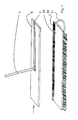
- Figure 1a discloses one elongated cleaning cloth support or holder frame 10 of cleaning device in accordance with the invention.
- a corresponding cleaning device is disclosed in figure 2 as seen from the left end thereof and provided with a looped cleaning cloth or fabric 9.
- the support comprises a body portion 6 provided with slots 12 which receive special sweeping blades or lips 7.
- the body portion 6 can be made e.g. from steel, aluminium, plastics or the like material suitable for this purpose.
- the sweeping blades 7 can be made e.g. from rubber, plastic or foamed plastic, or then they can be formed by means of suitable brushes.
- the sweeping blades 7 can be provided, if desired, with sharp sweeping or drying edges 17.
- the blades are threaded into their position within the slots 12 of the body portion 6 from the other end of the body portion 6 in a per se known manner. It is noted herein that it is possible to have only one blade instead of two blades, and that the blade or lip 7 is not the essential part of the invention, but that the invention can also be implemented without any blades, as will be described later.
- a spring element 4 has been attached by screws 5 on top of the body portion 6.
- the spring element 4 is biased such that it slightly bears against the upper surface of the body 6. It can be lifted off from the body surface, i.e. is movable relative to the body portion 6 in a manner illustrated by the two-headed arrow.
- the spring element 4 can be made from a spring steel level rod, as is the case in figures 1a and 2, or e.g. from a suitably formed spring wire structure.
- Various suitable spring elements for providing the biased holding of the cleaning cloth which can be utilised in the invention are well known by the skilled person, and will thus not be explained in more detail.
- An attachment pivot structure 2 of the stem portion 1 is mounted on the upper side of the free end of the spring element 4 by means of screws 3.
- the stem 1 is shown only partially, but the skilled person understands that it can be of any suitable length, such as between 0,5 to 1,5 meters long.
- the stem 1 and the pivot structure 2 enabling a pivoting attachment of the stem 1 to the body portion 6 can be of any known type, e.g. any of the solutions disclosed in the above referred prior art publications.
- Figure 1b corresponds otherwise figure 1a, but discloses an embodiment in which the elongated cleaning cloth support 10 is of an essentially long structure. In such case it may occur that the biasing force of the spring element 4 is not sufficient enough. In such case the spring element 4 can be locked from the free end thereof to the body 6 by means of a clamp or locking device 14.
- the clamp can be of any appropriate type providing releasable locking.
- Figure 2 discloses an embodiment in which a cleaning cloth 9 has been threaded to cover the body portion 6.
- the cleaning cloth 9 is annular, i.e. has a shape of an endless loop, and is arranged to be threaded around a support portion of the cleaning device support frame 10 through an opening in the other side edge of the loop.
- the material of the cleaning cloth 9 can consist of any appropriate material used for cleaning cloths in general, such as clothes made from cotton, terry, felt, microfibers, artificial fibers, woven linen, etc. It is also possible to turn the looped cloth 9 around, i.e. inside up, so that utilisation of both sides of the loop is enabled.
- the sweeping cloth 9 is threaded to surround the supporting body portion 6 through the other end opening thereof and is placed to lie under the spring element 4 so as to be held in its desired position by means of the spring element. Therefore the cloth 9 remains steadily in its position during the cleaning procedures.
- the spring element 4 is lifted off from the body surface, e.g. by means of lifting the stem 1 as illustrated by the arrows in figures 1a and 1b.
- the looped cleaning cloth 9 is adapted to be attached to the cleaning device by threading the looped cloth around a bar means 8 extending below the body portion 6 from the other end 11 thereof.
- the bar means 8 can be fixed to an end plate 11 provided in the other end of the body 6.
- a difference to the solution of figure 2 is that now it is possible to use the blade 7, and more precisely the sharp edge 17, for sweeping or drying the surface when this is desired.
- the blades 7 provide bearing support for the cleaning cloth as it is pushed against the surface to be cleaned.
- the cloth 9 has to be removed around the body portion 6.
- FIGs 4a and 4b illustrate the use of the figure 3 arrangement.
- the other of the blades 7 is used to bear the cloth 9 against the surface (not shown) whereas the other blade remains free.
- This other blade can be utilised for precleaning of the surface, for example for cleaning away stones etc. small particles or rubbish which otherwise would enter into the cleaning cloth 9.
- the cloth 9 is swung around the body portion 6, whereby it is possible to use the other of the blades 7 for e.g. drying purposes.
- This solution provides advantage e.g. when washing windows, since only one device is needed which can be used both for the washing (by means of the replaceable / rotatable cloth 9) and for drying by mean of the blade 7.
- the bar means 8 and the slot between at least the other of the blades 7 is arranged to be substantially narrow, or even such that the blade 7 bears against the bar means 8. This provides a corresponding holding effect as what is achieved by means of the spring element 4.
- the bar means 8 may also be provided with a slot or opening 21 extending over the entire length thereof, whereby the bar means 8 form a C-shaped structure.
- a cleaning cloth 19 can be threaded into this kind of structure, said cleaning cloth being provided with a special retaining bulb 20, such as a narrow rod etc. sewed within the cleaning cloth.
- the bulb 20 is threaded inside the bar means 8 such that it becomes retained by the bar means.
- Figure 6 discloses a solution in which the cleaning device is provided with a cleaning cloth 9A and/or 9B which does not form a loop.
- Figures 1 to 6 disclose an elongated cleaning cloth support 10 which is provided with two blades 7 which in turn are provided with drying tips or edges 17.
- these blades can be utilised in the actual cleaning operation, as they can be used as elements bearing the cloth against the surface to be cleaned.
- the left hand side blade 7 bears the cloth against the surface while the device is moved to the right.
- the remaining part of the cloth follows the support device, and it can absorb / dry any water left behind on the surface while the device is forwarded.
- Figure 7 discloses one additional embodiment.
- the body portion 6 is provided to have a substantially flat structure.
- a cleaning cloth 29 used in this has a looped shape, but now such that the other end thereof is closed.
- the open end of the cloth is threaded through the opening 30, as disclosed by arrow, to surround the body frame 6.
- a flap or loop 31 can be used when drawing the cloth loop around the body 6.
- a spring element 4 is released so that it may bear against the body portion 6 and retain the cloth in its position. It is possible to provide the flap portion 31 with suitable means for attachment and the surface of the end of the cloth 29 with appropriate counterparts so that the flap portion can also be utilised in closing the end opening 30 and in holding the cleaning cloth 29 around the support frame 6.
- the cleaning device in accordance with the present invention can be intended for sweeping floor or roof surfaces or similar, in which case the stem portion is provided by means of a subtantially long pivoted stem, or then a hand held cleaning device in which the stem portion is provided by means of a substantially short stem with no pivoting parts or similar short hand grip, for cleaning e.g. windows or table surfaces.
- the invention provides an apparatus and a method by which a significant improvement can be achieved in cleaning work. It should be noted that the foregoing examples of the embodiments of the invention are not intended to restrict the scope of the invention to the specific forms presented above but the present invention is meant rather to cover all modifications, similarities and alternatives which are included in the spirit and scope of the present invention, as defined by the appended claims.
Landscapes
- Cleaning Implements For Floors, Carpets, Furniture, Walls, And The Like (AREA)
- Treatment Of Fiber Materials (AREA)
- Control Of Washing Machine And Dryer (AREA)
- Inking, Control Or Cleaning Of Printing Machines (AREA)
- Silver Salt Photography Or Processing Solution Therefor (AREA)
- Measurement And Recording Of Electrical Phenomena And Electrical Characteristics Of The Living Body (AREA)
- Golf Clubs (AREA)
Applications Claiming Priority (2)
| Application Number | Priority Date | Filing Date | Title |
|---|---|---|---|
| FI980453A FI108397B (fi) | 1998-02-27 | 1998-02-27 | Siivousliina ja siivouslaite sekõ menetelmõ siivouksessa |
| FI980453 | 1998-02-27 |
Publications (3)
| Publication Number | Publication Date |
|---|---|
| EP0938863A2 true EP0938863A2 (fr) | 1999-09-01 |
| EP0938863A3 EP0938863A3 (fr) | 2001-04-18 |
| EP0938863B1 EP0938863B1 (fr) | 2007-04-11 |
Family
ID=8551055
Family Applications (1)
| Application Number | Title | Priority Date | Filing Date |
|---|---|---|---|
| EP99660038A Expired - Lifetime EP0938863B1 (fr) | 1998-02-27 | 1999-02-25 | Ustensile de nettoyage, tissu de nettoyage et méthode de nettoyage |
Country Status (4)
| Country | Link |
|---|---|
| EP (1) | EP0938863B1 (fr) |
| AT (1) | ATE359019T1 (fr) |
| DE (1) | DE69935746T2 (fr) |
| FI (1) | FI108397B (fr) |
Cited By (4)
| Publication number | Priority date | Publication date | Assignee | Title |
|---|---|---|---|---|
| WO2006067014A1 (fr) * | 2004-12-22 | 2006-06-29 | BSH Bosch und Siemens Hausgeräte GmbH | Dispositif de type serpilliere humide a support plat |
| WO2006097154A1 (fr) * | 2005-03-16 | 2006-09-21 | Carl Freudenberg Kg | Garniture d'essuyage |
| WO2006097093A1 (fr) * | 2005-03-18 | 2006-09-21 | Peter Sieger | Procede pour faire fonctionner une tete de nettoyage de surface, et tete de nettoyage de surface servant a la mise en oeuvre de ce procede |
| CN100444775C (zh) * | 2006-09-25 | 2008-12-24 | 张卫 | 多功能拖把 |
Families Citing this family (1)
| Publication number | Priority date | Publication date | Assignee | Title |
|---|---|---|---|---|
| DE102015010021A1 (de) * | 2015-08-06 | 2017-02-09 | Carl Freudenberg Kg | Fußboden-Reinigungsgerät |
Family Cites Families (3)
| Publication number | Priority date | Publication date | Assignee | Title |
|---|---|---|---|---|
| US1946321A (en) * | 1933-08-09 | 1934-02-06 | Hester W Hunter | Cleaning device |
| CH263480A (de) * | 1946-12-14 | 1949-08-31 | Rosenberger Frei Anna | Zum Auftragen von Bodenwichse bestimmtes Gerät. |
| US5477582A (en) * | 1994-05-10 | 1995-12-26 | Azuma Industrial Co., Ltd. | Mop sheet holder, and mop sheet therefor |
-
1998
- 1998-02-27 FI FI980453A patent/FI108397B/fi not_active IP Right Cessation
-
1999
- 1999-02-25 AT AT99660038T patent/ATE359019T1/de not_active IP Right Cessation
- 1999-02-25 EP EP99660038A patent/EP0938863B1/fr not_active Expired - Lifetime
- 1999-02-25 DE DE69935746T patent/DE69935746T2/de not_active Expired - Lifetime
Cited By (9)
| Publication number | Priority date | Publication date | Assignee | Title |
|---|---|---|---|---|
| WO2006067014A1 (fr) * | 2004-12-22 | 2006-06-29 | BSH Bosch und Siemens Hausgeräte GmbH | Dispositif de type serpilliere humide a support plat |
| CN100571599C (zh) * | 2004-12-22 | 2009-12-23 | Bsh博施及西门子家用器具有限公司 | 配有平面保持器的湿式擦拭器 |
| WO2006097154A1 (fr) * | 2005-03-16 | 2006-09-21 | Carl Freudenberg Kg | Garniture d'essuyage |
| EP1704808A1 (fr) * | 2005-03-16 | 2006-09-27 | Carl Freudenberg KG | Garniture de balai |
| CN100593999C (zh) * | 2005-03-16 | 2010-03-17 | 卡尔弗罗伊登柏格两合公司 | 带有擦拭覆层的擦拭系统 |
| US9198555B2 (en) | 2005-03-16 | 2015-12-01 | Carl Freudenberg Kg | Mop cover |
| NO337748B1 (no) * | 2005-03-16 | 2016-06-13 | Freudenberg Carl Kg | Moppovertrekk |
| WO2006097093A1 (fr) * | 2005-03-18 | 2006-09-21 | Peter Sieger | Procede pour faire fonctionner une tete de nettoyage de surface, et tete de nettoyage de surface servant a la mise en oeuvre de ce procede |
| CN100444775C (zh) * | 2006-09-25 | 2008-12-24 | 张卫 | 多功能拖把 |
Also Published As
| Publication number | Publication date |
|---|---|
| EP0938863B1 (fr) | 2007-04-11 |
| DE69935746D1 (de) | 2007-05-24 |
| EP0938863A3 (fr) | 2001-04-18 |
| ATE359019T1 (de) | 2007-05-15 |
| DE69935746T2 (de) | 2008-01-17 |
| FI980453L (fi) | 1999-08-28 |
| FI108397B (fi) | 2002-01-31 |
| FI980453A0 (fi) | 1998-02-27 |
Similar Documents
| Publication | Publication Date | Title |
|---|---|---|
| CN210493962U (zh) | 一种扫拖一体机的拖地清洁机构 | |
| US4945599A (en) | Cap system for sponge mops | |
| US5655250A (en) | Floor cleaning implement | |
| JP2009513259A (ja) | 清掃用具 | |
| KR20140145714A (ko) | 걸레 회전형 청소장치 | |
| EP0938863B1 (fr) | Ustensile de nettoyage, tissu de nettoyage et méthode de nettoyage | |
| CN108175346B (zh) | 立刮折甩清洁工具 | |
| US20110173768A1 (en) | Reversed Angled Squeegee | |
| CN103696209B (zh) | 一种挤压脱水装置 | |
| PT808601E (pt) | Equipamento de limpeza, em particular para esfregar de modo húmido e molhado | |
| EP2941164B1 (fr) | Procédé permettant de nettoyer une surface et accessoire de nettoyage | |
| KR20140033983A (ko) | 안정하게 탈부착되는 고무 블레이드를 구비한 유리창 청소기구 | |
| KR102019107B1 (ko) | 물걸레 청소기 | |
| KR200487622Y1 (ko) | 탈수 및 지지용 헤드를 구비한 패드형 대걸레 | |
| US5313683A (en) | Household cleaning implement | |
| CN211093832U (zh) | 一种平板拖把 | |
| US20070240270A1 (en) | Device for Cleaning Floors and Similar Surfaces | |
| JP3071400B2 (ja) | 箒に着合して用いる払掃具 | |
| CN111329414A (zh) | 一种地面摩擦动力开环拖地带收卷式拖把 | |
| CN211022494U (zh) | 一种吸水吸尘拖把 | |
| CN223041480U (zh) | 一种平板拖把用拖布、平板拖把和拖把桶 | |
| CN212118069U (zh) | 一种地面摩擦动力开环拖地带收卷式拖把 | |
| CN116369799B (zh) | 一种多功能地毯清洗装置 | |
| CN222693324U (zh) | 清洁桶 | |
| FI87981C (fi) | Avtorkningsanordning |
Legal Events
| Date | Code | Title | Description |
|---|---|---|---|
| PUAI | Public reference made under article 153(3) epc to a published international application that has entered the european phase |
Free format text: ORIGINAL CODE: 0009012 |
|
| 17P | Request for examination filed |
Effective date: 19990304 |
|
| AK | Designated contracting states |
Kind code of ref document: A2 Designated state(s): AT BE CH DE DK ES FI FR GB GR IE IT LI LU MC NL PT SE |
|
| AX | Request for extension of the european patent |
Free format text: AL;LT;LV;MK;RO;SI |
|
| PUAL | Search report despatched |
Free format text: ORIGINAL CODE: 0009013 |
|
| AK | Designated contracting states |
Kind code of ref document: A3 Designated state(s): AT BE CH CY DE DK ES FI FR GB GR IE IT LI LU MC NL PT SE |
|
| AX | Request for extension of the european patent |
Free format text: AL;LT;LV;MK;RO;SI |
|
| AKX | Designation fees paid |
Free format text: AT BE CH DE DK ES FI FR GB GR IE IT LI LU MC NL PT SE |
|
| 17Q | First examination report despatched |
Effective date: 20020321 |
|
| GRAP | Despatch of communication of intention to grant a patent |
Free format text: ORIGINAL CODE: EPIDOSNIGR1 |
|
| RAP1 | Party data changed (applicant data changed or rights of an application transferred) |
Owner name: SAPPAX OY |
|
| RIN1 | Information on inventor provided before grant (corrected) |
Inventor name: HEINONEN, AARO |
|
| RBV | Designated contracting states (corrected) |
Designated state(s): AT BE CH CY DE DK ES FI FR GB GR IE IT LI LU MC NL PT SE |
|
| GRAS | Grant fee paid |
Free format text: ORIGINAL CODE: EPIDOSNIGR3 |
|
| GRAA | (expected) grant |
Free format text: ORIGINAL CODE: 0009210 |
|
| AK | Designated contracting states |
Kind code of ref document: B1 Designated state(s): AT BE CH CY DE DK ES FI FR GB GR IE IT LI LU MC NL PT SE |
|
| PG25 | Lapsed in a contracting state [announced via postgrant information from national office to epo] |
Ref country code: LI Free format text: LAPSE BECAUSE OF FAILURE TO SUBMIT A TRANSLATION OF THE DESCRIPTION OR TO PAY THE FEE WITHIN THE PRESCRIBED TIME-LIMIT Effective date: 20070411 Ref country code: FI Free format text: LAPSE BECAUSE OF FAILURE TO SUBMIT A TRANSLATION OF THE DESCRIPTION OR TO PAY THE FEE WITHIN THE PRESCRIBED TIME-LIMIT Effective date: 20070411 Ref country code: CH Free format text: LAPSE BECAUSE OF FAILURE TO SUBMIT A TRANSLATION OF THE DESCRIPTION OR TO PAY THE FEE WITHIN THE PRESCRIBED TIME-LIMIT Effective date: 20070411 |
|
| REG | Reference to a national code |
Ref country code: GB Ref legal event code: FG4D |
|
| REG | Reference to a national code |
Ref country code: SE Ref legal event code: TRGR |
|
| REG | Reference to a national code |
Ref country code: CH Ref legal event code: EP |
|
| REG | Reference to a national code |
Ref country code: IE Ref legal event code: FG4D |
|
| REF | Corresponds to: |
Ref document number: 69935746 Country of ref document: DE Date of ref document: 20070524 Kind code of ref document: P |
|
| PG25 | Lapsed in a contracting state [announced via postgrant information from national office to epo] |
Ref country code: ES Free format text: LAPSE BECAUSE OF FAILURE TO SUBMIT A TRANSLATION OF THE DESCRIPTION OR TO PAY THE FEE WITHIN THE PRESCRIBED TIME-LIMIT Effective date: 20070722 |
|
| PG25 | Lapsed in a contracting state [announced via postgrant information from national office to epo] |
Ref country code: PT Free format text: LAPSE BECAUSE OF FAILURE TO SUBMIT A TRANSLATION OF THE DESCRIPTION OR TO PAY THE FEE WITHIN THE PRESCRIBED TIME-LIMIT Effective date: 20070911 |
|
| NLV1 | Nl: lapsed or annulled due to failure to fulfill the requirements of art. 29p and 29m of the patents act | ||
| REG | Reference to a national code |
Ref country code: CH Ref legal event code: PL |
|
| PG25 | Lapsed in a contracting state [announced via postgrant information from national office to epo] |
Ref country code: AT Free format text: LAPSE BECAUSE OF FAILURE TO SUBMIT A TRANSLATION OF THE DESCRIPTION OR TO PAY THE FEE WITHIN THE PRESCRIBED TIME-LIMIT Effective date: 20070411 |
|
| EN | Fr: translation not filed | ||
| PG25 | Lapsed in a contracting state [announced via postgrant information from national office to epo] |
Ref country code: BE Free format text: LAPSE BECAUSE OF FAILURE TO SUBMIT A TRANSLATION OF THE DESCRIPTION OR TO PAY THE FEE WITHIN THE PRESCRIBED TIME-LIMIT Effective date: 20070411 |
|
| PG25 | Lapsed in a contracting state [announced via postgrant information from national office to epo] |
Ref country code: NL Free format text: LAPSE BECAUSE OF FAILURE TO SUBMIT A TRANSLATION OF THE DESCRIPTION OR TO PAY THE FEE WITHIN THE PRESCRIBED TIME-LIMIT Effective date: 20070411 Ref country code: DK Free format text: LAPSE BECAUSE OF FAILURE TO SUBMIT A TRANSLATION OF THE DESCRIPTION OR TO PAY THE FEE WITHIN THE PRESCRIBED TIME-LIMIT Effective date: 20070411 |
|
| PLBE | No opposition filed within time limit |
Free format text: ORIGINAL CODE: 0009261 |
|
| STAA | Information on the status of an ep patent application or granted ep patent |
Free format text: STATUS: NO OPPOSITION FILED WITHIN TIME LIMIT |
|
| 26N | No opposition filed |
Effective date: 20080114 |
|
| PG25 | Lapsed in a contracting state [announced via postgrant information from national office to epo] |
Ref country code: IT Free format text: LAPSE BECAUSE OF FAILURE TO SUBMIT A TRANSLATION OF THE DESCRIPTION OR TO PAY THE FEE WITHIN THE PRESCRIBED TIME-LIMIT Effective date: 20070411 Ref country code: GR Free format text: LAPSE BECAUSE OF FAILURE TO SUBMIT A TRANSLATION OF THE DESCRIPTION OR TO PAY THE FEE WITHIN THE PRESCRIBED TIME-LIMIT Effective date: 20070712 Ref country code: FR Free format text: LAPSE BECAUSE OF FAILURE TO SUBMIT A TRANSLATION OF THE DESCRIPTION OR TO PAY THE FEE WITHIN THE PRESCRIBED TIME-LIMIT Effective date: 20071207 |
|
| GBPC | Gb: european patent ceased through non-payment of renewal fee |
Effective date: 20080225 |
|
| PG25 | Lapsed in a contracting state [announced via postgrant information from national office to epo] |
Ref country code: MC Free format text: LAPSE BECAUSE OF NON-PAYMENT OF DUE FEES Effective date: 20080228 |
|
| PG25 | Lapsed in a contracting state [announced via postgrant information from national office to epo] |
Ref country code: FR Free format text: LAPSE BECAUSE OF FAILURE TO SUBMIT A TRANSLATION OF THE DESCRIPTION OR TO PAY THE FEE WITHIN THE PRESCRIBED TIME-LIMIT Effective date: 20070411 |
|
| PG25 | Lapsed in a contracting state [announced via postgrant information from national office to epo] |
Ref country code: IE Free format text: LAPSE BECAUSE OF NON-PAYMENT OF DUE FEES Effective date: 20080225 |
|
| PG25 | Lapsed in a contracting state [announced via postgrant information from national office to epo] |
Ref country code: GB Free format text: LAPSE BECAUSE OF NON-PAYMENT OF DUE FEES Effective date: 20080225 |
|
| PG25 | Lapsed in a contracting state [announced via postgrant information from national office to epo] |
Ref country code: CY Free format text: LAPSE BECAUSE OF FAILURE TO SUBMIT A TRANSLATION OF THE DESCRIPTION OR TO PAY THE FEE WITHIN THE PRESCRIBED TIME-LIMIT Effective date: 20070411 |
|
| PG25 | Lapsed in a contracting state [announced via postgrant information from national office to epo] |
Ref country code: LU Free format text: LAPSE BECAUSE OF NON-PAYMENT OF DUE FEES Effective date: 20080225 |
|
| PGFP | Annual fee paid to national office [announced via postgrant information from national office to epo] |
Ref country code: DE Payment date: 20170210 Year of fee payment: 19 |
|
| PGFP | Annual fee paid to national office [announced via postgrant information from national office to epo] |
Ref country code: SE Payment date: 20180206 Year of fee payment: 20 |
|
| REG | Reference to a national code |
Ref country code: DE Ref legal event code: R119 Ref document number: 69935746 Country of ref document: DE |
|
| PG25 | Lapsed in a contracting state [announced via postgrant information from national office to epo] |
Ref country code: DE Free format text: LAPSE BECAUSE OF NON-PAYMENT OF DUE FEES Effective date: 20180901 |
|
| REG | Reference to a national code |
Ref country code: SE Ref legal event code: EUG |