EP0938953A2 - Magazin für ein Druckluftnagelgerät - Google Patents
Magazin für ein Druckluftnagelgerät Download PDFInfo
- Publication number
- EP0938953A2 EP0938953A2 EP99102794A EP99102794A EP0938953A2 EP 0938953 A2 EP0938953 A2 EP 0938953A2 EP 99102794 A EP99102794 A EP 99102794A EP 99102794 A EP99102794 A EP 99102794A EP 0938953 A2 EP0938953 A2 EP 0938953A2
- Authority
- EP
- European Patent Office
- Prior art keywords
- magazine
- compressed
- guiding channel
- firing tool
- access flap
- Prior art date
- Legal status (The legal status is an assumption and is not a legal conclusion. Google has not performed a legal analysis and makes no representation as to the accuracy of the status listed.)
- Withdrawn
Links
Images



Classifications
-
- B—PERFORMING OPERATIONS; TRANSPORTING
- B25—HAND TOOLS; PORTABLE POWER-DRIVEN TOOLS; MANIPULATORS
- B25C—HAND-HELD NAILING OR STAPLING TOOLS; MANUALLY OPERATED PORTABLE STAPLING TOOLS
- B25C5/00—Manually operated portable stapling tools; Hand-held power-operated stapling tools; Staple feeding devices therefor
- B25C5/16—Staple-feeding devices, e.g. with feeding means, supports for staples or accessories concerning feeding devices
- B25C5/1637—Supports for the staples being fed
- B25C5/1641—Supports for the staples being fed allowing the feeding of a variety of elements
- B25C5/1658—Supports for the staples being fed allowing the feeding of a variety of elements of different sizes of staples
-
- B—PERFORMING OPERATIONS; TRANSPORTING
- B25—HAND TOOLS; PORTABLE POWER-DRIVEN TOOLS; MANIPULATORS
- B25C—HAND-HELD NAILING OR STAPLING TOOLS; MANUALLY OPERATED PORTABLE STAPLING TOOLS
- B25C1/00—Hand-held nailing tools; Nail feeding devices
- B25C1/001—Nail feeding devices
- B25C1/005—Nail feeding devices for rows of contiguous nails
Definitions
- the present invention relates to a magazine for a compressed-air nail firing tool.
- Compressed-air nail firing tools are constituted by a body comprising a cylindrical head, in which the hammer body slides, and a handle which protrudes from said head.
- a firing channel is aligned in a downward region with the cylindrical head, and a nail guiding channel, belonging to a magazine, enters said firing channel.
- the nails to be fired are made to advance in the guiding channel by a pusher and are individually positioned in the firing channel, from which they are ejected by the hammer body by way of a stem which can slide in said channel and acts axially on the nails.
- the nails to be inserted in the magazine are joined in packs by interposing a suitable adhesive.
- fastening elements of shapes suitable to be fired by a firing tool which will be called hereinafter, generically, fasteners have different lengths according to requirements, and for each length the guiding channel must have dimensions which are suitable to support the fasteners during their advancement. Solutions have been proposed which use magazines in which the guiding channel has a plurality of longitudinal slots which are arranged at different levels and are adapted to guide the fasteners to be used.
- the presence of said plurality of slots determines a certain play in the fastener guiding channel; accordingly, especially when the pack of fasteners is constituted by a plurality of separate units, the pressure applied by the pusher often causes the overlap of two or more units inside the guiding channel, consequently jamming the tool.
- the aim of the present invention is to solve the above-cited drawbacks of conventional devices, i.e., to provide a device which allows quicker and less awkward access to the guiding channel and the same time prevents as much as possible any overlap of the packs of nails.
- an object of the present invention is to provide a structure which is simple, relatively easy to provide in practice, safe in use, effective in operation and relatively low in cost.
- a compressed-air nail firing tool which comprises a fastener guiding channel delimited laterally by a pair of flat and parallel walls, characterized in that one of said walls is fixed to the body of the firing tool, while the other wall is constituted by an access flap which is hinged to the fixed wall about a longitudinal axis, so as to allow lateral opening of the fastener guiding channel over at least a significant part of its length, means being further provided for retaining the access flap in the position for closing the fastener guiding channel.
- the reference numeral 1 generally designates the body of the compressed-air nail firing tool, comprising a cylindrical head 2 whereto a handle 3 is rigidly coupled; said handle has, at its end, a coupling sleeve 4 for connection to a source of compressed air.
- a firing tube 5 protrudes from the head 2 and is axially crossed by a channel 6 for firing the nails 7.
- the fasteners 7 form packs which are contained in a magazine which is generally designated by the reference numeral 8.
- the magazine 8 comprises a box-like element which is composed of a fixed wall 9, a movable wall 10, hereinafter termed access flap, and an additional wall portion 11, which is fixed to the wall 9 flush to the access flap 10 and covers the part of the wall 9 that is not covered by the access flap 10.
- the portion 11, together with the fixed wall 9, delimits a compartment for containing the pusher, described hereinafter, when the magazine is in the loading position.
- the access flap 10 is hinged to the fixed wall 9 at the edge that lies furthest from the handle 3 about the axis A. Hinging is provided by means of coaxial pins 12 and 13 which are rotatably inserted in bushes 14 and 15, rigidly coupled to the portion 11 and to the end of the fixed wall 9 which is proximate to the firing tube 5.
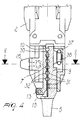
- the access flap 10 has, at the end that lies adjacent to the firing tube 5, an external protrusion 16 whereto a body 19 is fixed by means of screws 17 and 18; said body 19 has an L-shaped configuration, with a wall which is co-planar to the access flap and a front wall which is perpendicular to the access flap 10 and is adapted to close the firing channel to the rear.
- a recess 20 is formed in the protrusion 16 and a raised portion 21, rigidly coupled to the body 19, is accommodated in said recess.
- a hole 22 is formed in the raised portion 21 (see Figure 5) and a pin 23 is guided therein; a lug 25 protrudes externally from said pin through a slot 24 of the raised portion and acts as a button for actuating the pin 23.
- the pin 23 is pushed outward, through the front wall of the body 19 at right angles to the access flap 10, by a spring 26 so that when the access flap is in the closure position the pin 23 can engage, by means of a projection 27, in a hole 28 formed in the firing tube 5.
- a pin 29 which acts as contrast element prevents the pin 23 from escaping, when the access flap is open, from the hole 22 under the thrust of the spring 26.
- the channel 30 for guiding the fasteners 7 is formed between the fixed wall 9 and the access flap 10; in the illustrated example, said fasteners are constituted by T-shaped nails.
- Longitudinal parallel slots 31 and, respectively, 32 are formed both in the wall 9 and in the access flap 10, so that in the closed position of the magazine 8, i.e., when the access flap 10 is adjacent to the wall 9, the slots 31 lie exactly opposite the slots 32; said slots 31 and 32 are meant to accommodate the head of the fasteners 7 according to their length.
- the advancement of the fasteners 7 in the channel 30 is determined by the pusher 33, which in the position for loading the nail firing tool is accommodated in a seat formed at the end of the magazine that lies furthest from the tube 5, between the portion 11 and the fixed wall 9.
- An actuation lever 34 is rigidly coupled to the pusher 33, and a slot 35 is formed in said lever.
- a retractable pin 36 protrudes from the portion 11 and is loaded by a spring which is not shown in the drawing.
- the access flap 10 When the nail firing tool is in the operating configuration, the access flap 10 is closed and the pusher 33, with the lever 34 disengaged from the pin 36, is actuated toward the firing tube 5 by a spring 37 which winds around a pulley 38 rotatably supported in the fixed wall 9 proximate to the firing tube 5.
- the spring 37 lies within a chamber 39 which is formed laterally with respect to the fixed wall 9 by a covering plate 39a.
- One of the ends of the spring is fixed to the pusher 33, while the opposite end is fixed to the fixed wall 9 proximate to the portion 11.
- the pusher 33 causes the fasteners 7 to advance along the guiding channel 30 toward the firing tube 5, so that the first one of said fasteners arranges itself in position inside the firing channel 6, ready to be ejected by the hammer blade.
- Closing the access flap 10 requires no additional operations, since conveniently in the firing tube, at the level of the pin 23, a ramp 40 is provided which, during the closure of the access flap, initially facilitates the retraction of the pin 23 into the hole 22 of the raised portion 21 and the subsequent engagement of the projection 27 in the hole 28 of the firing tube 5.
- a ramp 40 is provided which, during the closure of the access flap, initially facilitates the retraction of the pin 23 into the hole 22 of the raised portion 21 and the subsequent engagement of the projection 27 in the hole 28 of the firing tube 5.
- the pusher 33 due to the tension of the spring 37, causes the advancement of the fasteners 7 toward the firing channel 6.
- the projection 27 of the pivot 23 has a chamfer 41 which, when said projection 27 is inserted in the respective hole of the tube, generates a force component which is adapted to retain the access flap 10 so that it rests against the fixed wall 9, thus reducing the transverse play of the fasteners.
- the access flap 10 can be hinged to the side of the magazine that is adjacent to the handle instead of to the opposite side. All the details may also be replaced with other technically equivalent ones.
Landscapes
- Engineering & Computer Science (AREA)
- Mechanical Engineering (AREA)
- Portable Nailing Machines And Staplers (AREA)
Applications Claiming Priority (2)
| Application Number | Priority Date | Filing Date | Title |
|---|---|---|---|
| IT1998BO000023U IT244715Y1 (it) | 1998-02-27 | 1998-02-27 | Caricatore per pistola chiodatrice ad aria compressa . |
| ITBO980023U | 1998-02-27 |
Publications (2)
| Publication Number | Publication Date |
|---|---|
| EP0938953A2 true EP0938953A2 (de) | 1999-09-01 |
| EP0938953A3 EP0938953A3 (de) | 2000-07-12 |
Family
ID=11342769
Family Applications (1)
| Application Number | Title | Priority Date | Filing Date |
|---|---|---|---|
| EP99102794A Withdrawn EP0938953A3 (de) | 1998-02-27 | 1999-02-24 | Magazin für ein Druckluftnagelgerät |
Country Status (3)
| Country | Link |
|---|---|
| US (1) | US6092711A (de) |
| EP (1) | EP0938953A3 (de) |
| IT (1) | IT244715Y1 (de) |
Families Citing this family (17)
| Publication number | Priority date | Publication date | Assignee | Title |
|---|---|---|---|---|
| EP1033209B1 (de) * | 1999-03-04 | 2007-05-30 | Max Co., Ltd. | Mechanismus des Magazins für eine Nagelmaschine |
| US6913180B2 (en) * | 2001-07-16 | 2005-07-05 | George A. Schuster | Nail gun |
| FR2831231B1 (fr) * | 2001-10-18 | 2004-06-11 | Prospection & Inventions | Bande d element de fixation et chargeur pour une telle bande pour appareil d entrainement de tels elements de fixation |
| US6715657B2 (en) * | 2002-04-29 | 2004-04-06 | Mu-Yu Chen | Magazine for use in nail stapler |
| US20050001007A1 (en) * | 2003-05-29 | 2005-01-06 | Butzen Robert W. | Pneumatic nailer |
| JP4569252B2 (ja) * | 2004-10-08 | 2010-10-27 | マックス株式会社 | 動力駆動釘打機 |
| USD560108S1 (en) | 2005-07-19 | 2008-01-22 | Milwaukee Electric Tool Corporation | Power tool, such as a nailer |
| US20070075112A1 (en) * | 2005-10-04 | 2007-04-05 | Porth Chris H | Nose assembly for a fastener driving tool |
| US20080006673A1 (en) * | 2005-12-28 | 2008-01-10 | Chou Chi C | Fastener feeding device for stapler |
| KR100722208B1 (ko) * | 2006-01-06 | 2007-05-29 | 치쳉 초우 | 스테플러 |
| TW200823018A (en) * | 2006-11-30 | 2008-06-01 | Samson Power Tool Co Ltd | Nozzle assembly for nail-roll type nailer |
| US20080190987A1 (en) * | 2007-02-14 | 2008-08-14 | Po-Feng Huang | Driver Guiding Set for Power Nail Gun |
| US20100084452A1 (en) * | 2008-10-08 | 2010-04-08 | Yi-Kuan Lee | Combination of strike rod and barrel for nail guns |
| US8083116B2 (en) * | 2009-10-14 | 2011-12-27 | De Poan Pneumatic Corp. | Braking and driving mechanism for nail gun |
| TW201219170A (en) * | 2010-11-15 | 2012-05-16 | quan-fu Zheng | comprising an insertion slot that switchably receives therein various stitching plates that define at opposite ends thereof stitching notches and a receiving slot receiving therein a clamping piece for holding the stitching plate |
| US9993912B2 (en) * | 2015-09-30 | 2018-06-12 | Samson Power Tool Co. Ltd. | Nail pushing device for nail gun |
| WO2021195188A1 (en) | 2020-03-25 | 2021-09-30 | Milwaukee Electric Tool Corporation | Powered fastener driver |
Family Cites Families (9)
| Publication number | Priority date | Publication date | Assignee | Title |
|---|---|---|---|---|
| US3834602A (en) * | 1973-01-26 | 1974-09-10 | Fastener Corp | Fastener driving tool |
| DK133284A (da) * | 1983-03-11 | 1984-09-12 | Signode Corp | Soeminddrivningsapparat og soemmagasineringsenhed |
| DE3426173A1 (de) * | 1984-07-16 | 1986-01-23 | Hilti Ag, Schaan | Eintreibgeraet fuer befestigungselemente, wie naegel, klammern und dergleichen |
| US4815647A (en) * | 1986-11-10 | 1989-03-28 | Chou Joseph S Y | Multiple-function magazine for tee nails to be used with a nailing gun |
| US4801062A (en) * | 1987-06-18 | 1989-01-31 | Duo-Fast Corporation | Side load magazine for a fastener driving tool |
| US5368213A (en) * | 1993-04-29 | 1994-11-29 | Senco Products, Inc. | Magazine for a pneumatic fastener driving tool |
| AU667162B2 (en) * | 1993-05-13 | 1996-03-07 | Stanley-Bostitch, Inc. | Fastener driving device particularly suited for use as a roofing nailer |
| US5813588A (en) * | 1996-10-09 | 1998-09-29 | Lin; George | Magazine assembly for fastener driving tools |
| US5873509A (en) * | 1998-04-20 | 1999-02-23 | Liao; Walter | Magazine structure for a power stapler |
-
1998
- 1998-02-27 IT IT1998BO000023U patent/IT244715Y1/it active
-
1999
- 1999-02-24 EP EP99102794A patent/EP0938953A3/de not_active Withdrawn
- 1999-02-25 US US09/257,478 patent/US6092711A/en not_active Expired - Fee Related
Also Published As
| Publication number | Publication date |
|---|---|
| EP0938953A3 (de) | 2000-07-12 |
| ITBO980023U1 (it) | 1999-08-27 |
| IT244715Y1 (it) | 2002-03-14 |
| US6092711A (en) | 2000-07-25 |
Similar Documents
| Publication | Publication Date | Title |
|---|---|---|
| US6092711A (en) | Magazine for compressed-air nail firing tool | |
| EP1454716B1 (de) | Pneumatisches Nagelgerät zum Befestigen von Elementen | |
| JP2640988B2 (ja) | 釘打機における釘の空打防止装置 | |
| US2174219A (en) | Stapling pliers | |
| US5522533A (en) | Magazine for use with fastener driving tool | |
| EP0828587B1 (de) | Zuführvorrichtung für ein befestigungsmitteleintreibgerät | |
| CA1112115A (en) | Apparatus for driving fasteners | |
| JPH04365567A (ja) | 釘打機におけるプッシャ装置 | |
| US4801062A (en) | Side load magazine for a fastener driving tool | |
| JPH02177951A (ja) | 手術用ステープラー | |
| JP2001293667A (ja) | 釘打機のノーズ部に対する釘の案内構造 | |
| ITBO980005A1 (it) | Fissatrice ad aria compressa. | |
| EP0634251B1 (de) | Vorrichtung zum leichten Entfernen von verklemmten Heftklammern | |
| US4903880A (en) | Side load magazine for a fastener driving tool | |
| CA2863691A1 (en) | Staples feeder assembly with concealed slider for pneumatic fastener magazine | |
| IE41492B1 (en) | Explosive-powered fastener-driving tool | |
| US4432484A (en) | Tool for driving metal fasteners in a frame and setting its rear closing panel | |
| JP4579520B2 (ja) | 安定部材を備えたマガジン組立体 | |
| US6938813B1 (en) | Nail stapler nozzle | |
| US6880738B2 (en) | Propellant charge magazine for a setting tool | |
| US8356738B2 (en) | Staple feeding apparatus for spring powered staplers | |
| JP3419537B2 (ja) | 釘打機のマガジン | |
| JP3724545B2 (ja) | 釘打機の除釘装置 | |
| JPH10193280A (ja) | 固着具打込機の給送装置 | |
| EP4389352A1 (de) | Eintreibwerkzeug |
Legal Events
| Date | Code | Title | Description |
|---|---|---|---|
| PUAI | Public reference made under article 153(3) epc to a published international application that has entered the european phase |
Free format text: ORIGINAL CODE: 0009012 |
|
| AK | Designated contracting states |
Kind code of ref document: A2 Designated state(s): AT BE CH CY DE DK ES FI FR GB GR IE IT LI LU MC NL PT SE |
|
| AX | Request for extension of the european patent |
Free format text: AL;LT;LV;MK;RO;SI |
|
| PUAL | Search report despatched |
Free format text: ORIGINAL CODE: 0009013 |
|
| AK | Designated contracting states |
Kind code of ref document: A3 Designated state(s): AT BE CH CY DE DK ES FI FR GB GR IE IT LI LU MC NL PT SE |
|
| AX | Request for extension of the european patent |
Free format text: AL;LT;LV;MK;RO;SI |
|
| AKX | Designation fees paid | ||
| STAA | Information on the status of an ep patent application or granted ep patent |
Free format text: STATUS: THE APPLICATION IS DEEMED TO BE WITHDRAWN |
|
| 18D | Application deemed to be withdrawn |
Effective date: 20010113 |
|
| REG | Reference to a national code |
Ref country code: DE Ref legal event code: 8566 |