EP0938989A2 - Befestigung eines Sensors - Google Patents
Befestigung eines Sensors Download PDFInfo
- Publication number
- EP0938989A2 EP0938989A2 EP98122972A EP98122972A EP0938989A2 EP 0938989 A2 EP0938989 A2 EP 0938989A2 EP 98122972 A EP98122972 A EP 98122972A EP 98122972 A EP98122972 A EP 98122972A EP 0938989 A2 EP0938989 A2 EP 0938989A2
- Authority
- EP
- European Patent Office
- Prior art keywords
- sensor
- component
- reaction component
- container
- piping
- Prior art date
- Legal status (The legal status is an assumption and is not a legal conclusion. Google has not performed a legal analysis and makes no representation as to the accuracy of the status listed.)
- Granted
Links
Images
Classifications
-
- B—PERFORMING OPERATIONS; TRANSPORTING
- B60—VEHICLES IN GENERAL
- B60H—ARRANGEMENTS OF HEATING, COOLING, VENTILATING OR OTHER AIR-TREATING DEVICES SPECIALLY ADAPTED FOR PASSENGER OR GOODS SPACES OF VEHICLES
- B60H1/00—Heating, cooling or ventilating devices
- B60H1/00507—Details, e.g. mounting arrangements, desaeration devices
-
- F—MECHANICAL ENGINEERING; LIGHTING; HEATING; WEAPONS; BLASTING
- F25—REFRIGERATION OR COOLING; COMBINED HEATING AND REFRIGERATION SYSTEMS; HEAT PUMP SYSTEMS; MANUFACTURE OR STORAGE OF ICE; LIQUEFACTION SOLIDIFICATION OF GASES
- F25B—REFRIGERATION MACHINES, PLANTS OR SYSTEMS; COMBINED HEATING AND REFRIGERATION SYSTEMS; HEAT PUMP SYSTEMS
- F25B41/00—Fluid-circulation arrangements
- F25B41/40—Fluid line arrangements
-
- F—MECHANICAL ENGINEERING; LIGHTING; HEATING; WEAPONS; BLASTING
- F25—REFRIGERATION OR COOLING; COMBINED HEATING AND REFRIGERATION SYSTEMS; HEAT PUMP SYSTEMS; MANUFACTURE OR STORAGE OF ICE; LIQUEFACTION SOLIDIFICATION OF GASES
- F25B—REFRIGERATION MACHINES, PLANTS OR SYSTEMS; COMBINED HEATING AND REFRIGERATION SYSTEMS; HEAT PUMP SYSTEMS
- F25B43/00—Arrangements for separating or purifying gases or liquids; Arrangements for vaporising the residuum of liquid refrigerant, e.g. by heat
- F25B43/006—Accumulators
-
- G—PHYSICS
- G01—MEASURING; TESTING
- G01D—MEASURING NOT SPECIALLY ADAPTED FOR A SPECIFIC VARIABLE; ARRANGEMENTS FOR MEASURING TWO OR MORE VARIABLES NOT COVERED IN A SINGLE OTHER SUBCLASS; TARIFF METERING APPARATUS; MEASURING OR TESTING NOT OTHERWISE PROVIDED FOR
- G01D11/00—Component parts of measuring arrangements not specially adapted for a specific variable
- G01D11/24—Housings ; Casings for instruments
-
- G—PHYSICS
- G01—MEASURING; TESTING
- G01K—MEASURING TEMPERATURE; MEASURING QUANTITY OF HEAT; THERMALLY-SENSITIVE ELEMENTS NOT OTHERWISE PROVIDED FOR
- G01K1/00—Details of thermometers not specially adapted for particular types of thermometer
- G01K1/14—Supports; Fastening devices; Arrangements for mounting thermometers in particular locations
-
- F—MECHANICAL ENGINEERING; LIGHTING; HEATING; WEAPONS; BLASTING
- F25—REFRIGERATION OR COOLING; COMBINED HEATING AND REFRIGERATION SYSTEMS; HEAT PUMP SYSTEMS; MANUFACTURE OR STORAGE OF ICE; LIQUEFACTION SOLIDIFICATION OF GASES
- F25B—REFRIGERATION MACHINES, PLANTS OR SYSTEMS; COMBINED HEATING AND REFRIGERATION SYSTEMS; HEAT PUMP SYSTEMS
- F25B2700/00—Sensing or detecting of parameters; Sensors therefor
- F25B2700/04—Refrigerant level
Definitions
- the present invention relates to a sensor fixture according to the preamble part of claim 1.
- (Fig.) sensors for air conditioning systems are designed with a foot part, made of metal, which receives the reaction component of the sensor and serves to fix the sensor at its operating location.
- the reaction component incorporated into said foot part is positioned and sealed; e.g., by crimping.
- Said foot part is formed with manipulating means, e.g. a hexagonal part, and with a fixture element; e.g., a threaded projection, by means of which said sensor is fixed in the piping- or container-component.
- manipulating means e.g. a hexagonal part
- a fixture element e.g., a threaded projection
- two sensors are shown in a condenser of a air conditioning system.
- One of the sensors is a pressure pick-up or pressure switch threaded with a threaded protrusion of its foot part into a threaded bore of a closure lid of a collection channel of a condenser, said closure lid having a channel for the cooling agent or the pressure transmission, respectively.
- the other of said sensors is a level sensor, the probe of which is received in a foot part which penetrates the bottom portion of the condenser and reaches into said collecting channel and which is fixed by means of an external thread engaging in a threaded bore of said bottom portion.
- both sensors are only shown and described schematically, so that the detail designs of both sensors remain unclear.
- reaction component of the sensor is directly secured in the piping- or container-component, i.e. without using a reaction component receiving foot part, mounting space and weight can be saved.
- the production of the sensor is simplified and less costly. It may, with rational effort, only be necessary to structurally prepare the reaction component for the direct fixation in the piping- or container-component, and also to design the piping-and container- component in such a constructional way that the reaction component of the sensor can be directly affixed therein.
- a predetermined rotary operating position can be realized as well.
- a holding socket is provided which is pre-designed for the direct fixation of the reaction component only.
- the connecting section of the reaction component is attached such that the cooling agent can actuate or contact the reaction component directly within the holding socket.
- a sealing element is interposed between the reaction component and the holding socket.
- the reaction component is respectively fixed in one predetermined rotary position, so that its terminals are already oriented for easy connection with a cable connector.
- connection means can be used in order to fix the reaction component directly and in a predetermined rotary position at the piping- or container-component.
- a crimped connection With a crimped connection, the necessary holding effect and sealing effect are achieved by crimping a crimping edge or discrete crimping projections and by a positive and forceful holding.
- the necessary positive and forceful holding can be easily achieved as well as the desired rotary positioning.
- An additional or alternative glued or welded connection can secure the reaction component very reliably; hermetically sealed and durable.
- parts of the connecting means are already formed at the reaction component, such that no foot part is needed to fix the reaction component at the piping- or container-component.
- the piping- or container- component can be constituted by such elements of an air conditioning system which conventionally served to carry one or several sensors by means of their foot parts.
- the function component itself already constitutes the sensor which can be a single stage or a multistage pressure switch or a pressure measuring device, a thermostat or temperature measuring device, a level measuring or switching device, a flow rate metering or registering device, or a combination sensor containing, e.g., more than one pressure switch or measuring device or temperature switching or measuring device.
- a simple fixation of the reaction component is possible in the holding socket, wherein the crimping edge of the holding socket grips over the supporting shoulder of the connecting section so that the connecting section is positively and forcefully fixed within the holding socket, preferably in a predetermined rotary position.
- additional positioning means could be provided.
- the bayonet-connection serves to fix the reaction component and to determine the rotary operation position.
- the connection can be designed such that it allows a single rotary position only.
- annular groove for inserting a sealing ring is formed within the holding socket according to claim 10.
- the sealing ring is located on the outer periphery of the reaction component connection portion.
- the piping- or container- component is made of metal, preferably light metal, allowing a durable crimping connection.
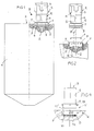
- a sensor fixture B exemplifies in Figs. 1 and 2 in a vehicle air conditioning system (not shown) how, e.g., a pressure switch responding to the pressure of the cooling agent is fixed to a container 1.
- Said pressure switch generally is a sensor S consisting, in this case, only of a reaction component R which directly is attached in sensor fixture B to a piping- or container- component K containing a cooling agent.
- Component K is provided, e.g. in its topside or in a lid provided there, with a holding socket F into which the reaction component R engages with a connecting section 5.
- Said connecting section 5 is the end part of a, e.g.
- connection section 5 is thickened in relation to neck part 4 and is designed with a supporting shoulder 6. An inwardly displaced crimping edge 7 or part of holding socket F grips over said shoulder 6.
- Reaction component R can be fixed in a predetermined rotary operation position in relation to holding socket F.
- a sealing element D is inserted below reaction component R.
- a channel 2 for the cooling agent terminates inside said sealing element D such that the lower side of the connecting section 5 is in direct contact with the cooling agent within holding socket F.
- a connecting means V between the reaction component R and the component K in this case, a crimped connection is used.
- the connecting section 5 could be constituted by gluing or welding.
- the holding socket F in component K is a blind bore recess 11 having a slightly larger diameter than the connecting section 5 of the reaction component R. Said recess 11 can be made by drilling or turning.
- a circular, upwardly-open groove 10 is formed for sealing element D.
- Channel 2 terminates essentially in the center of holding socket F.
- the crimping edge 7 can be continuous in circumferential direction and protrudes beyond the topside of component K. Alternatively, instead of a continuous crimping edge, separate crimping projections 7' could be provided.
- an O-ring constituting said sealing element D Prior to inserting the reaction component R into the holding socket F, an O-ring constituting said sealing element D is inserted into groove 10. As soon as the connecting section 5 of the reaction component R is inserted into the holding socket, the upright crimping edge 7 is crimped by means of a suitable tool (not shown).
- the reaction component R can contain, as usual, at least one sensing member G which is exposed freely position at the lower side of connecting section 5 in order to come in contact with the cooling agent.
- sensing member G can be covered by a diaphragm 8 which is clamped in the shown embodiment by means of a ring flange 9 to connecting section 5.
- the reaction component R is directly fixed to the topside of the container; e.g., a dryer- or accumulator- container of an air conditioning system.
- a container e.g., a dryer- or accumulator- container of an air conditioning system.
- a container could be equipped with a separate lid- or bottom- part which contains the at least one holding socket F. Said lid- or bottom- part can be attached to the container in a conventional manner.
- said component K also could be a so-called connection-fitting, securable to the top of an cooling agent container or a piping, respectively, thus serving as a carrier for the reaction component R.
- Component K instead could be a condenser-housing part or closure lid, a dryer cartridge or dryer cartridge insert, or a compressor housing or closure lid.
- Component K can be made of metal, preferably light metal, and could be disk-shaped.
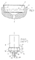
- modified holding socket F is shown in enlarged scale. It is formed by turning, drilling, milling or pressing with a dimension allowing for the insertion of the connecting section 5 of reaction component R with radial clearance prior to forcing crimping edge 7 inwardly in order to position and hold reaction component R sealed by sealing element D. Said sealing element here is positioned between the wall of recess 11 and is compressed radially.
- the projecting crimping edge 7 could be omitted.
- the shown sensor fixture B having directly secured connecting section 5 in the holding socket F significantly reduces mounting depth as well as mounting space conventionally occupied in diametrical direction when compared with the relatively bulky known foot part (see Fig. 5).
- a bayonet-connection is used as connecting means V.
- the connecting portion 5 of the reaction component R is equipped with stud-like bayonet-engagement elements 13 apt to be fitted into the wall of recess 11' of holding socket F.
- the correctly engaged bayonet-connection presses reaction component R with pre-load outer sealing element D inserted into annular groove 10.
- a projecting edge 7, as shown in Fig. 3, can be provided to save mounting depth. This is, however, not necessary.
- a predetermined rotary operation position of reaction component can be achieved.
- said bayonet connection is designed such that it allows exclusively one rotary position.
- a predetermined rotary position of reaction component can be desirable for automatized assembly steps, e.g., when connecting a cable connector with a predetermined orientation to terminals of the sensor.
- Fig. 5 represents a conventional sensor fixture.
- the sensor S is provided with a foot part 20 having a hexagonal section 21 and a threaded projection 18.
- Foot part 20 is normally made from metal.
- the reaction component R of the sensor is positioned and secured within foot part 20, e.g. by potting or crimping at 15. Channel 19 extends through threaded projection 18 towards reaction component R. Insert has to be prefabricated with reaction component R.
- Below foot part 20, O-ring 22 is provided below foot part 20, O-ring 22 is provided. Inside foot part 20 an additional sealing element O is needed.
- Component K has to have threaded bore 23 and supply channel 24.
- Foot part 20 occupies considerable mounting height and also relatively large space aside threaded bore 23. In addition, the considerable weight of foot part 20 is undesirable. In the interior of foot part 20 a further sealing element is needed.
Landscapes
- Engineering & Computer Science (AREA)
- Physics & Mathematics (AREA)
- Mechanical Engineering (AREA)
- Thermal Sciences (AREA)
- General Engineering & Computer Science (AREA)
- General Physics & Mathematics (AREA)
- Chemical & Material Sciences (AREA)
- Analytical Chemistry (AREA)
- Power Engineering (AREA)
- Measuring Fluid Pressure (AREA)
- Air-Conditioning For Vehicles (AREA)
- Geophysics And Detection Of Objects (AREA)
- Adjustment Of The Magnetic Head Position Track Following On Tapes (AREA)
Applications Claiming Priority (2)
| Application Number | Priority Date | Filing Date | Title |
|---|---|---|---|
| DE29803388U | 1998-02-26 | ||
| DE29803388U DE29803388U1 (de) | 1998-02-26 | 1998-02-26 | Sensorbefestigung |
Publications (3)
| Publication Number | Publication Date |
|---|---|
| EP0938989A2 true EP0938989A2 (de) | 1999-09-01 |
| EP0938989A3 EP0938989A3 (de) | 2001-09-05 |
| EP0938989B1 EP0938989B1 (de) | 2004-07-07 |
Family
ID=8053252
Family Applications (1)
| Application Number | Title | Priority Date | Filing Date |
|---|---|---|---|
| EP98122972A Expired - Lifetime EP0938989B1 (de) | 1998-02-26 | 1998-12-03 | Befestigung eines Sensors |
Country Status (3)
| Country | Link |
|---|---|
| EP (1) | EP0938989B1 (de) |
| DE (2) | DE29803388U1 (de) |
| ES (1) | ES2223103T3 (de) |
Cited By (1)
| Publication number | Priority date | Publication date | Assignee | Title |
|---|---|---|---|---|
| CN106274363A (zh) * | 2016-08-29 | 2017-01-04 | 博耐尔汽车电气系统有限公司 | 一种新型的风道传感器的改进结构 |
Families Citing this family (4)
| Publication number | Priority date | Publication date | Assignee | Title |
|---|---|---|---|---|
| DE102012112737A1 (de) * | 2012-12-20 | 2014-04-03 | Conti Temic Microelectronic Gmbh | Sensoranordnung und Verfahren zur Herstellung einer Sensoranordnung |
| DE102015012507B4 (de) | 2015-09-24 | 2020-10-08 | Audi Ag | Verfahren zur Montage einer Sensorbaugruppe an einem ein kältemittelführenden Bauteil sowie Sensorbaugruppe und kältemittelführendes Bauteil jeweils zur Durchführung des Verfahrens |
| DE102015012500B4 (de) | 2015-09-24 | 2019-02-07 | Audi Ag | Blockverbinderanordnung zum Anschließen einer Sensorbaugruppe an ein kältemittelführendes Bauteil |
| CN109986930B (zh) * | 2019-05-07 | 2024-02-02 | 安徽安凯汽车股份有限公司 | 一种便于拆卸维修的纯电动客车用水暖加热器 |
Citations (1)
| Publication number | Priority date | Publication date | Assignee | Title |
|---|---|---|---|---|
| DE4319293A1 (de) | 1993-06-10 | 1994-12-15 | Behr Gmbh & Co | Klimaanlage für ein Fahrzeug |
Family Cites Families (6)
| Publication number | Priority date | Publication date | Assignee | Title |
|---|---|---|---|---|
| GB1220842A (en) * | 1968-05-24 | 1971-01-27 | Thermo Electric Dev Manchester | Thermo-couple holder |
| US4217765A (en) * | 1979-06-04 | 1980-08-19 | Atlantic Richfield Company | Heat exchanger-accumulator |
| NL9000744A (nl) * | 1990-03-29 | 1991-10-16 | Weinand Antonius Maria Stapelb | Geoptimaliseerd thermostatisch expansieventiel en een daarvan voorziene koelmachine. |
| EP0539944A3 (en) * | 1991-10-31 | 1993-08-04 | Eaton Corporation | Expansion valve and temperature sensing assembly therefor |
| FR2686690B1 (fr) * | 1992-01-28 | 1994-04-29 | Jaeger | Systeme de capteur comprenant un plongeur destine a etre place dans l'alesage d'un support. |
| FR2723202B1 (fr) * | 1994-07-28 | 1996-10-25 | Magneti Marelli France Sa | Capteur de grandeur physique, notamment un capteurde temperature |
-
1998
- 1998-02-26 DE DE29803388U patent/DE29803388U1/de not_active Expired - Lifetime
- 1998-12-03 ES ES98122972T patent/ES2223103T3/es not_active Expired - Lifetime
- 1998-12-03 EP EP98122972A patent/EP0938989B1/de not_active Expired - Lifetime
- 1998-12-03 DE DE69824946T patent/DE69824946T2/de not_active Expired - Fee Related
Patent Citations (1)
| Publication number | Priority date | Publication date | Assignee | Title |
|---|---|---|---|---|
| DE4319293A1 (de) | 1993-06-10 | 1994-12-15 | Behr Gmbh & Co | Klimaanlage für ein Fahrzeug |
Cited By (1)
| Publication number | Priority date | Publication date | Assignee | Title |
|---|---|---|---|---|
| CN106274363A (zh) * | 2016-08-29 | 2017-01-04 | 博耐尔汽车电气系统有限公司 | 一种新型的风道传感器的改进结构 |
Also Published As
| Publication number | Publication date |
|---|---|
| DE69824946T2 (de) | 2005-08-25 |
| EP0938989B1 (de) | 2004-07-07 |
| DE29803388U1 (de) | 1998-05-14 |
| ES2223103T3 (es) | 2005-02-16 |
| DE69824946D1 (de) | 2004-08-12 |
| EP0938989A3 (de) | 2001-09-05 |
Similar Documents
| Publication | Publication Date | Title |
|---|---|---|
| US7281421B2 (en) | Package for a tire pressure sensor assembly | |
| US7017403B2 (en) | Vehicle wheel comprising a tire and an assembly consisting of a valve a device for measuring the tire pressure and a spring for holding said device in the tire | |
| US6227055B1 (en) | Pressure sensor assembly with direct backside sensing | |
| US6619129B2 (en) | Three-piece pressure sensor with high pressure stainless steel sensing element | |
| US7454965B2 (en) | Method and apparatus for mounting a tire pressure monitoring device | |
| US4954677A (en) | Tire pressure sensor for motor vehicles | |
| US5774047A (en) | Tire pressure sensing system including improved switch and location indicator | |
| US7886589B2 (en) | Electronic unit for measuring operating parameters of a vehicle wheel | |
| US4435983A (en) | Handle stem for a bicycle | |
| US20020189335A1 (en) | Sensor mounting structure and semiconductor pressure sensor for motor vehicles | |
| JPH10272919A (ja) | コンデンサのコレクタープロフィール部材用の挿入部材 | |
| EP1024034A2 (de) | Gehäuse für Drucksensor | |
| US6557406B2 (en) | Device for measuring the tire pressure in a pneumatic tire of a vehicle | |
| EP1096241A1 (de) | Integrierter Druck- und Temperatursensor für Fluide unter hohem Druck | |
| EP1335195B1 (de) | Einsatz gespritzte Einheit eines Druckwandlers mit einem Druckgefäss | |
| US20110079337A1 (en) | Tire Valve Fixing Element | |
| EP0938989B1 (de) | Befestigung eines Sensors | |
| US5977496A (en) | Switch sensor with internal shear pin design | |
| US6050147A (en) | Pressure sensor assembly | |
| US6006610A (en) | Arrangement of a sensor housing on a wall | |
| US7336162B2 (en) | Double mold shot pull to seat universal TPMS sensor | |
| US5424874A (en) | Mechanism for fitting lens to an extension | |
| US5957269A (en) | Watertight structure of mounting portion | |
| US20240123775A1 (en) | Tire monitoring apparatus, system, and methods | |
| JPS6238433Y2 (de) |
Legal Events
| Date | Code | Title | Description |
|---|---|---|---|
| PUAI | Public reference made under article 153(3) epc to a published international application that has entered the european phase |
Free format text: ORIGINAL CODE: 0009012 |
|
| AK | Designated contracting states |
Kind code of ref document: A2 Designated state(s): AT BE CH CY DE DK ES FI FR GB GR IE IT LI LU MC NL PT SE |
|
| AX | Request for extension of the european patent |
Free format text: AL;LT;LV;MK;RO;SI |
|
| PUAL | Search report despatched |
Free format text: ORIGINAL CODE: 0009013 |
|
| AK | Designated contracting states |
Kind code of ref document: A3 Designated state(s): AT BE CH CY DE DK ES FI FR GB GR IE IT LI LU MC NL PT SE |
|
| AX | Request for extension of the european patent |
Free format text: AL;LT;LV;MK;RO;SI |
|
| 17P | Request for examination filed |
Effective date: 20020207 |
|
| AKX | Designation fees paid |
Free format text: DE ES FR GB IT |
|
| 17Q | First examination report despatched |
Effective date: 20020801 |
|
| RAP1 | Party data changed (applicant data changed or rights of an application transferred) |
Owner name: FINBER S.P.A |
|
| GRAP | Despatch of communication of intention to grant a patent |
Free format text: ORIGINAL CODE: EPIDOSNIGR1 |
|
| GRAS | Grant fee paid |
Free format text: ORIGINAL CODE: EPIDOSNIGR3 |
|
| GRAA | (expected) grant |
Free format text: ORIGINAL CODE: 0009210 |
|
| AK | Designated contracting states |
Kind code of ref document: B1 Designated state(s): DE ES FR GB IT |
|
| REG | Reference to a national code |
Ref country code: GB Ref legal event code: FG4D |
|
| REF | Corresponds to: |
Ref document number: 69824946 Country of ref document: DE Date of ref document: 20040812 Kind code of ref document: P |
|
| REG | Reference to a national code |
Ref country code: ES Ref legal event code: FG2A Ref document number: 2223103 Country of ref document: ES Kind code of ref document: T3 |
|
| ET | Fr: translation filed | ||
| PLBE | No opposition filed within time limit |
Free format text: ORIGINAL CODE: 0009261 |
|
| STAA | Information on the status of an ep patent application or granted ep patent |
Free format text: STATUS: NO OPPOSITION FILED WITHIN TIME LIMIT |
|
| 26N | No opposition filed |
Effective date: 20050408 |
|
| PGFP | Annual fee paid to national office [announced via postgrant information from national office to epo] |
Ref country code: ES Payment date: 20081215 Year of fee payment: 11 |
|
| PGFP | Annual fee paid to national office [announced via postgrant information from national office to epo] |
Ref country code: IT Payment date: 20081219 Year of fee payment: 11 |
|
| PGFP | Annual fee paid to national office [announced via postgrant information from national office to epo] |
Ref country code: FR Payment date: 20081211 Year of fee payment: 11 |
|
| PGFP | Annual fee paid to national office [announced via postgrant information from national office to epo] |
Ref country code: DE Payment date: 20090129 Year of fee payment: 11 |
|
| PGFP | Annual fee paid to national office [announced via postgrant information from national office to epo] |
Ref country code: GB Payment date: 20081217 Year of fee payment: 11 |
|
| GBPC | Gb: european patent ceased through non-payment of renewal fee |
Effective date: 20091203 |
|
| REG | Reference to a national code |
Ref country code: FR Ref legal event code: ST Effective date: 20100831 |
|
| PG25 | Lapsed in a contracting state [announced via postgrant information from national office to epo] |
Ref country code: FR Free format text: LAPSE BECAUSE OF NON-PAYMENT OF DUE FEES Effective date: 20091231 |
|
| PG25 | Lapsed in a contracting state [announced via postgrant information from national office to epo] |
Ref country code: DE Free format text: LAPSE BECAUSE OF NON-PAYMENT OF DUE FEES Effective date: 20100701 |
|
| PG25 | Lapsed in a contracting state [announced via postgrant information from national office to epo] |
Ref country code: GB Free format text: LAPSE BECAUSE OF NON-PAYMENT OF DUE FEES Effective date: 20091203 |
|
| PG25 | Lapsed in a contracting state [announced via postgrant information from national office to epo] |
Ref country code: IT Free format text: LAPSE BECAUSE OF NON-PAYMENT OF DUE FEES Effective date: 20091203 |
|
| REG | Reference to a national code |
Ref country code: ES Ref legal event code: FD2A Effective date: 20110404 |
|
| PG25 | Lapsed in a contracting state [announced via postgrant information from national office to epo] |
Ref country code: ES Free format text: LAPSE BECAUSE OF NON-PAYMENT OF DUE FEES Effective date: 20110322 |
|
| PG25 | Lapsed in a contracting state [announced via postgrant information from national office to epo] |
Ref country code: ES Free format text: LAPSE BECAUSE OF NON-PAYMENT OF DUE FEES Effective date: 20091204 |