EP0938992B1 - A motor vehicle body - Google Patents
A motor vehicle body Download PDFInfo
- Publication number
- EP0938992B1 EP0938992B1 EP19990103582 EP99103582A EP0938992B1 EP 0938992 B1 EP0938992 B1 EP 0938992B1 EP 19990103582 EP19990103582 EP 19990103582 EP 99103582 A EP99103582 A EP 99103582A EP 0938992 B1 EP0938992 B1 EP 0938992B1
- Authority
- EP
- European Patent Office
- Prior art keywords
- channel
- longitudinal
- body according
- longitudinal beam
- guide
- Prior art date
- Legal status (The legal status is an assumption and is not a legal conclusion. Google has not performed a legal analysis and makes no representation as to the accuracy of the status listed.)
- Expired - Lifetime
Links
- 230000008878 coupling Effects 0.000 claims description 3
- 238000010168 coupling process Methods 0.000 claims description 3
- 238000005859 coupling reaction Methods 0.000 claims description 3
- 238000005096 rolling process Methods 0.000 claims description 2
- 230000001154 acute effect Effects 0.000 claims 1
- 238000004519 manufacturing process Methods 0.000 description 6
- 239000000470 constituent Substances 0.000 description 1
- 238000005520 cutting process Methods 0.000 description 1
- 230000008030 elimination Effects 0.000 description 1
- 238000003379 elimination reaction Methods 0.000 description 1
- 229910052751 metal Inorganic materials 0.000 description 1
- 230000004048 modification Effects 0.000 description 1
- 238000012986 modification Methods 0.000 description 1
- 238000005192 partition Methods 0.000 description 1
- 238000003825 pressing Methods 0.000 description 1
- 230000009467 reduction Effects 0.000 description 1
- 238000007789 sealing Methods 0.000 description 1
- 238000003466 welding Methods 0.000 description 1
Images
Classifications
-
- B—PERFORMING OPERATIONS; TRANSPORTING
- B60—VEHICLES IN GENERAL
- B60J—WINDOWS, WINDSCREENS, NON-FIXED ROOFS, DOORS, OR SIMILAR DEVICES FOR VEHICLES; REMOVABLE EXTERNAL PROTECTIVE COVERINGS SPECIALLY ADAPTED FOR VEHICLES
- B60J5/00—Doors
- B60J5/10—Doors arranged at the vehicle rear
- B60J5/12—Doors arranged at the vehicle rear slidable; foldable
-
- E—FIXED CONSTRUCTIONS
- E05—LOCKS; KEYS; WINDOW OR DOOR FITTINGS; SAFES
- E05D—HINGES OR SUSPENSION DEVICES FOR DOORS, WINDOWS OR WINGS
- E05D15/00—Suspension arrangements for wings
- E05D15/06—Suspension arrangements for wings for wings sliding horizontally more or less in their own plane
- E05D15/0621—Details, e.g. suspension or supporting guides
- E05D15/0626—Details, e.g. suspension or supporting guides for wings suspended at the top
- E05D15/063—Details, e.g. suspension or supporting guides for wings suspended at the top on wheels with fixed axis
-
- E—FIXED CONSTRUCTIONS
- E05—LOCKS; KEYS; WINDOW OR DOOR FITTINGS; SAFES
- E05Y—INDEXING SCHEME ASSOCIATED WITH SUBCLASSES E05D AND E05F, RELATING TO CONSTRUCTION ELEMENTS, ELECTRIC CONTROL, POWER SUPPLY, POWER SIGNAL OR TRANSMISSION, USER INTERFACES, MOUNTING OR COUPLING, DETAILS, ACCESSORIES, AUXILIARY OPERATIONS NOT OTHERWISE PROVIDED FOR, APPLICATION THEREOF
- E05Y2900/00—Application of doors, windows, wings or fittings thereof
- E05Y2900/50—Application of doors, windows, wings or fittings thereof for vehicles
- E05Y2900/53—Type of wing
- E05Y2900/531—Doors
Definitions
- the present invention concerns a motor vehicle body according to the preamble of claim 1.
- a motor vehicle body of this kind is disclosed in US 4 544 198 A.
- Motor vehicles and, in particular, commercial vehicles are currently known which include one or more rectilinear longitudinal guides, to which slidable support elements are coupled such as, for example, runners both for the slidable side doors of the motor vehicle itself, or for bodies for gripping products and/or articles to be transported.
- slidable side doors to which the following description specifically refers without loss of generality thereby, there is an upper attachment guide having a support function and to which is slidingly coupled a runner that is firmly connected to an associated side door.
- the upper attachment guide is generally formed from an elongate body shaped to define a race for the rolling bodies of the associated runner, and having an attachment portion which is securely fixed, preferably by welding, to the lateral surface of a respective portion of the body.
- the manufacture of the elongate body and its subsequent connection to the body is relatively difficult and, in any case, involves relatively high manufacturing and assembly costs which, in many cases, are further increased due to the fact that the elongate body must necessarily be concealed and, in any case, isolated as it generally has one or more cutting edges.
- the elongate guide bodies once connected to the body, project from the body itself into the luggage compartment of the motor vehicle and are therefore relatively bulky and, usually, difficult for the users of the motor vehicle to tolerate.
- the object of the present invention is to manufacture a motor vehicle body which enables the problems described above to be overcome simply and economically.
- a motor vehicle body including at least one longitudinal guide for a movable element which can be displaced longitudinally with respect to the body, characterised in that it includes at least one shaped longitudinal beam, and in that the said longitudinal guide is formed directly on the said longitudinal beam and is defined by an intermediate longitudinal portion of the longitudinal beam itself.
- the longitudinal beam is hollow and the said longitudinal guide extends into the longitudinal beam itself.
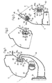
- the reference number 1 generally indicates a motor vehicle body including a plurality of pillars (not shown) and a roof 5 firmly connected to the pillars.
- the body 1 further includes two upper longitudinal beams 6, only one of which is shown in Figure 1, which beams, in the particular example described, laterally delimit the roof 5.
- Each beam 6 is formed from two profiled metal elements 7 and 8, manufactured by profiling, of which the first element 7 is located on the outside and remains partly in view in the finished motor vehicle, while the second element 8 is inside the motor vehicle in a position facing the corresponding second element 8 of the other beam 6.
- the outer first element 7 includes a horizontal first longitudinal flange 18 and a second longitudinal flange 19, which flanges are firmly connected to respective longitudinal flanges 21 and 22 of the second element 8 to form a shaped, box-like beam 6.
- the first element 7 together with a pair of the pillars mentioned above (not shown), defines a lateral aperture 23 which is closed by a sliding door 24 that is movable in a longitudinal direction orthogonal to the plane of Figure 1 towards and away from a closure position in which the door 24 is in abutment against a known sealing gasket 25 fitted to the flanges 19 and 22.
- an intermediate portion 26 of the second element 8, between the flanges 21 and 22, defines a longitudinal C-shape channel 28 having an aperture 28a facing the aperture 28a of the corresponding second element 8 of the other beam 6.
- the channel 28 is delimited by a substantially vertical base wall 29, two side walls 31 that face each other and are parallel and orthogonal to the wall 29, and two ribs 32.
- the ribs 32 converge, starting from the respective walls 31 in positions facing and spaced from the wall 29, to define respective retaining undercuts.
- the channel 28 defines a rectilinear portion of a longitudinal guide for a runner 33 for supporting the door 24.
- the runner 33 includes two or more wheels 34 housed in the channel 28 and which turn about respective axes 35 in contact with the lower wall 31 which therefore forms the race for the wheels 34 themselves.
- the beams 6 support a plurality of transversely movable bars 36, only one of which is partly illustrated in Figure 2, which, in use, enable various products or articles to be suspended or hooked on.
- each profiled second element 8 defines an associated longitudinal channel 37 which is delimited, in particular, by a vertical base wall 38, a flat, horizontal lower wall 39, an upper wall 41 and a rib 42 similar to the rib 32, and defines, together with the wall 39, an inlet opening 37a facing the aperture 37a of the channel 37 formed on the other beam 6.
- Each bar 36 has respective opposite end portions 43 on each of which it is rotatably coupled, in an axially fixed position, an associated wheel or roller 44 housed in the associated channel 37 in order to turn, in use, in contact with the wall 39 and enable the associated bar 36 to move parallel to itself within the body 1.
- the embodiment illustrated in Figure 3 concerns a body 45 which differs from the body 1 in some constructional details, and whose constituent parts are indicated, wherever possible, using the same reference numbers as the corresponding parts of the body 1.
- the intermediate portion 26 of one or both of the profiled second elements 8 defines a related longitudinal dovetailed channel 49 delimited by a base wall 51 and two side walls 52.
- the side walls 52 define an inlet opening 49a of the channel 49 facing the other profiled second element 8, and converge towards each other and towards the aperture 49a itself.
- each element gripping 50 includes a slider portion 53 which extends into the channel 49, and a gripper portion 54.
- the section of the portion 53 complements that of the channel 49 and, in particular, includes two projections 56 which slide in contact with the walls 52 of the channel 49, and are connected to each other by respective partition walls 57.
- the body 45 supports a roof 58 which is raised with respect to the beams 6, and coupled thereto.
- the roof 58 is coupled to the beam 6 by means of respective slidable dovetailed couplings, each of which includes an associated longitudinal dovetailed channel 59, similar to the channel 49, defined by an outer intermediate portion of the related profiled first element 7, and having an inlet opening 59a facing the outside.
- Each channel 59 forms a sliding guide for a plurality of attachment elements 60, only one of which is visible in Figure 3, firmly attached to the roof 58 and having associated slider portions 61 similar to the portions 53.
- the roof 58 is then locked in a longitudinal position by a releasable and controllable locking device, known and not shown.
- the constructional characteristics of the beams 6 avoid the use of elongate guide elements welded to the body.
- This essentially means that the beams 6 are formed from profiled bodies which, due to the fact that they are profiled, have, with respect to corresponding parts obtained by pressing, portions and/or walls with undercuts, and therefore define sliding guides for a plurality of runners or sliders normally used on motor vehicles, including part of a guide for a side door of the motor vehicle.
- the beams 6 can include a different number of profiled elements, and the profiled elements 7, 8 themselves can have shapes and geometries that are different from those described by way of example.
- the channels 28, 37, 49 and 59 can have shapes and geometries that are different from those described, and can be formed in different zones of the profiled elements 7 and 8.
- different runners or sliders from those described can be coupled with the channels 28, 37, 49 and 59, for example, to support attachment elements performing different functions from those indicated.
Landscapes
- Engineering & Computer Science (AREA)
- Mechanical Engineering (AREA)
- Power-Operated Mechanisms For Wings (AREA)
- Support Devices For Sliding Doors (AREA)
Applications Claiming Priority (2)
| Application Number | Priority Date | Filing Date | Title |
|---|---|---|---|
| ITTO980031 IT245800Y1 (it) | 1998-02-27 | 1998-02-27 | Telaio di un veicolo |
| ITTO980031U | 1998-02-27 |
Publications (3)
| Publication Number | Publication Date |
|---|---|
| EP0938992A2 EP0938992A2 (en) | 1999-09-01 |
| EP0938992A3 EP0938992A3 (en) | 2000-05-17 |
| EP0938992B1 true EP0938992B1 (en) | 2003-06-11 |
Family
ID=11416294
Family Applications (1)
| Application Number | Title | Priority Date | Filing Date |
|---|---|---|---|
| EP19990103582 Expired - Lifetime EP0938992B1 (en) | 1998-02-27 | 1999-02-24 | A motor vehicle body |
Country Status (4)
| Country | Link |
|---|---|
| EP (1) | EP0938992B1 (it) |
| DE (1) | DE69908676T2 (it) |
| ES (1) | ES2200420T3 (it) |
| IT (1) | IT245800Y1 (it) |
Families Citing this family (1)
| Publication number | Priority date | Publication date | Assignee | Title |
|---|---|---|---|---|
| KR101382777B1 (ko) * | 2013-02-15 | 2014-04-17 | 기아자동차주식회사 | 차량용 슬라이딩 도어의 로워레일 구조 |
Family Cites Families (5)
| Publication number | Priority date | Publication date | Assignee | Title |
|---|---|---|---|---|
| GB2080743B (en) * | 1980-07-17 | 1984-07-25 | Nissan Motor | Guide rail for a vehicle sliding door |
| JPS5915179A (ja) * | 1982-07-16 | 1984-01-26 | 日産自動車株式会社 | 自動車のスライドドア装置 |
| US4991905A (en) * | 1988-08-29 | 1991-02-12 | Suzuki Motor Company Limited | Vehicle construction of automobile provided with slide door |
| DE19714678C5 (de) * | 1997-04-09 | 2007-10-18 | Sommer-Fahrzeugbau Gmbh & Co | Schieberunge |
| DE29709542U1 (de) * | 1997-06-02 | 1998-10-01 | Ed. Scharwächter GmbH + Co Fahrzeugtechnik, 94491 Hengersberg | Fahrzeugaufbau |
-
1998
- 1998-02-27 IT ITTO980031 patent/IT245800Y1/it active
-
1999
- 1999-02-24 EP EP19990103582 patent/EP0938992B1/en not_active Expired - Lifetime
- 1999-02-24 DE DE1999608676 patent/DE69908676T2/de not_active Expired - Lifetime
- 1999-02-24 ES ES99103582T patent/ES2200420T3/es not_active Expired - Lifetime
Also Published As
| Publication number | Publication date |
|---|---|
| EP0938992A3 (en) | 2000-05-17 |
| ES2200420T3 (es) | 2004-03-01 |
| ITTO980031U1 (it) | 1999-08-27 |
| DE69908676D1 (de) | 2003-07-17 |
| IT245800Y1 (it) | 2002-03-26 |
| EP0938992A2 (en) | 1999-09-01 |
| DE69908676T2 (de) | 2004-05-13 |
Similar Documents
| Publication | Publication Date | Title |
|---|---|---|
| JP5010117B2 (ja) | 自動車用アルミ押出中空パネル及びその製造方法 | |
| US5024480A (en) | Bodywork for automobiles | |
| CN108136884A (zh) | 用于车门的齐平的玻璃装置,及对应的门、机动车、制造方法及密封装置 | |
| US20100293863A1 (en) | Extruded vehicle door sash | |
| US6030020A (en) | Seal or trim member including design for eliminating distortion at corners | |
| EP0938992B1 (en) | A motor vehicle body | |
| US20160185189A1 (en) | Glass pane having a profiled joint and trim, trim and production method for the glass pane | |
| US10053900B2 (en) | Center track design for a sliding door | |
| US20150174993A1 (en) | Vehicle door structure | |
| US20140292018A1 (en) | Seat rail for a vehicle seat of a motor vehicle and retaining arrangement of a retaining element of a vehicle seat on a seat rail | |
| US6595573B1 (en) | Bow configuration | |
| US20170136965A1 (en) | Bridging component and edge trim strip as well as system made from them | |
| US20210155084A1 (en) | Automobile having retractable rear quarter windows | |
| EP1090789A2 (en) | Guide for movable coverings and movable covering comprising said guide | |
| EP0885778B1 (en) | Sealing corner | |
| US10773650B2 (en) | Passenger motor vehicle luggage compartment cover | |
| US20090295194A1 (en) | Door frame for vehicle | |
| JPS604813Y2 (ja) | 自動車のスライド屋根 | |
| US3031223A (en) | Vehicle body with forward sliding windshield and side window structure | |
| EP1705327A3 (en) | Suspension guide for sliding doors | |
| GB2312460A (en) | Sealing, trimming or guiding strip for a vehicle | |
| CZ283930B6 (cs) | Vyklápěcí zařízení pro posuvné bočnice a střešní kryty | |
| EP2708690B1 (en) | Interior handle for opening the door of a motor vehicle | |
| JP3440039B2 (ja) | シートスライド装置のレール体構造 | |
| JPH0134892Y2 (it) |
Legal Events
| Date | Code | Title | Description |
|---|---|---|---|
| PUAI | Public reference made under article 153(3) epc to a published international application that has entered the european phase |
Free format text: ORIGINAL CODE: 0009012 |
|
| AK | Designated contracting states |
Kind code of ref document: A2 Designated state(s): DE ES FR GB IT SE |
|
| AX | Request for extension of the european patent |
Free format text: AL;LT;LV;MK;RO;SI |
|
| PUAL | Search report despatched |
Free format text: ORIGINAL CODE: 0009013 |
|
| AK | Designated contracting states |
Kind code of ref document: A3 Designated state(s): AT BE CH CY DE DK ES FI FR GB GR IE IT LI LU MC NL PT SE |
|
| AX | Request for extension of the european patent |
Free format text: AL;LT;LV;MK;RO;SI |
|
| RIC1 | Information provided on ipc code assigned before grant |
Free format text: 7B 60J 5/12 A, 7B 60J 5/06 B |
|
| 17P | Request for examination filed |
Effective date: 20000912 |
|
| AKX | Designation fees paid |
Free format text: DE ES FR GB IT SE |
|
| GRAH | Despatch of communication of intention to grant a patent |
Free format text: ORIGINAL CODE: EPIDOS IGRA |
|
| GRAH | Despatch of communication of intention to grant a patent |
Free format text: ORIGINAL CODE: EPIDOS IGRA |
|
| GRAA | (expected) grant |
Free format text: ORIGINAL CODE: 0009210 |
|
| AK | Designated contracting states |
Designated state(s): DE ES FR GB IT SE |
|
| REG | Reference to a national code |
Ref country code: GB Ref legal event code: FG4D |
|
| REF | Corresponds to: |
Ref document number: 69908676 Country of ref document: DE Date of ref document: 20030717 Kind code of ref document: P |
|
| REG | Reference to a national code |
Ref country code: SE Ref legal event code: TRGR |
|
| REG | Reference to a national code |
Ref country code: ES Ref legal event code: FG2A Ref document number: 2200420 Country of ref document: ES Kind code of ref document: T3 |
|
| ET | Fr: translation filed | ||
| PLBE | No opposition filed within time limit |
Free format text: ORIGINAL CODE: 0009261 |
|
| STAA | Information on the status of an ep patent application or granted ep patent |
Free format text: STATUS: NO OPPOSITION FILED WITHIN TIME LIMIT |
|
| 26N | No opposition filed |
Effective date: 20040312 |
|
| PGFP | Annual fee paid to national office [announced via postgrant information from national office to epo] |
Ref country code: ES Payment date: 20050209 Year of fee payment: 7 |
|
| PGFP | Annual fee paid to national office [announced via postgrant information from national office to epo] |
Ref country code: DE Payment date: 20060224 Year of fee payment: 8 |
|
| PGFP | Annual fee paid to national office [announced via postgrant information from national office to epo] |
Ref country code: FR Payment date: 20060227 Year of fee payment: 8 |
|
| PGFP | Annual fee paid to national office [announced via postgrant information from national office to epo] |
Ref country code: IT Payment date: 20060228 Year of fee payment: 8 |
|
| PG25 | Lapsed in a contracting state [announced via postgrant information from national office to epo] |
Ref country code: SE Free format text: LAPSE BECAUSE OF NON-PAYMENT OF DUE FEES Effective date: 20070225 |
|
| EUG | Se: european patent has lapsed | ||
| GBPC | Gb: european patent ceased through non-payment of renewal fee |
Effective date: 20070224 |
|
| REG | Reference to a national code |
Ref country code: FR Ref legal event code: ST Effective date: 20071030 |
|
| PG25 | Lapsed in a contracting state [announced via postgrant information from national office to epo] |
Ref country code: DE Free format text: LAPSE BECAUSE OF NON-PAYMENT OF DUE FEES Effective date: 20070901 |
|
| PGFP | Annual fee paid to national office [announced via postgrant information from national office to epo] |
Ref country code: SE Payment date: 20060202 Year of fee payment: 8 |
|
| PG25 | Lapsed in a contracting state [announced via postgrant information from national office to epo] |
Ref country code: GB Free format text: LAPSE BECAUSE OF NON-PAYMENT OF DUE FEES Effective date: 20070224 Ref country code: FR Free format text: LAPSE BECAUSE OF NON-PAYMENT OF DUE FEES Effective date: 20070228 |
|
| REG | Reference to a national code |
Ref country code: ES Ref legal event code: FD2A Effective date: 20070226 |
|
| PG25 | Lapsed in a contracting state [announced via postgrant information from national office to epo] |
Ref country code: ES Free format text: LAPSE BECAUSE OF NON-PAYMENT OF DUE FEES Effective date: 20070226 |
|
| PGFP | Annual fee paid to national office [announced via postgrant information from national office to epo] |
Ref country code: GB Payment date: 20060206 Year of fee payment: 8 |
|
| PG25 | Lapsed in a contracting state [announced via postgrant information from national office to epo] |
Ref country code: IT Free format text: LAPSE BECAUSE OF NON-PAYMENT OF DUE FEES Effective date: 20070224 |