EP0939006A2 - Befestigungseinheit einer Tragevorrichtung auf dem Dach eines Kraftfahrzeuges und Dach mit solcher Einheit - Google Patents
Befestigungseinheit einer Tragevorrichtung auf dem Dach eines Kraftfahrzeuges und Dach mit solcher Einheit Download PDFInfo
- Publication number
- EP0939006A2 EP0939006A2 EP99103581A EP99103581A EP0939006A2 EP 0939006 A2 EP0939006 A2 EP 0939006A2 EP 99103581 A EP99103581 A EP 99103581A EP 99103581 A EP99103581 A EP 99103581A EP 0939006 A2 EP0939006 A2 EP 0939006A2
- Authority
- EP
- European Patent Office
- Prior art keywords
- roof
- longitudinal
- support device
- guide
- carried
- Prior art date
- Legal status (The legal status is an assumption and is not a legal conclusion. Google has not performed a legal analysis and makes no representation as to the accuracy of the status listed.)
- Ceased
Links
- 230000002441 reversible effect Effects 0.000 claims description 2
- 230000000295 complement effect Effects 0.000 description 2
- 230000000712 assembly Effects 0.000 description 1
- 238000000429 assembly Methods 0.000 description 1
- 230000008878 coupling Effects 0.000 description 1
- 238000010168 coupling process Methods 0.000 description 1
- 238000005859 coupling reaction Methods 0.000 description 1
- 230000004048 modification Effects 0.000 description 1
- 238000012986 modification Methods 0.000 description 1
Images

Classifications
-
- B—PERFORMING OPERATIONS; TRANSPORTING
- B60—VEHICLES IN GENERAL
- B60R—VEHICLES, VEHICLE FITTINGS, OR VEHICLE PARTS, NOT OTHERWISE PROVIDED FOR
- B60R9/00—Supplementary fittings on vehicle exterior for carrying loads, e.g. luggage, sports gear or the like
- B60R9/04—Carriers associated with vehicle roof
Definitions
- the present invention concerns a unit for attaching a support device to the roof of a motor vehicle.
- the present invention concerns a unit for attaching a luggage rack to the roof of a motor vehicle, and the following description refers explicitly to this embodiment without loss of generality thereby.
- luggage racks are usually attached to the roof of the motor vehicle using connection units comprising a plurality of support elements disposed on various portions of the roof, and the same number of anchorage devices which hold the support elements against the roof.
- the anchorage devices usually comprise respective anchorage brackets which are attached to retaining portions of the roof, and associated nut and screw assemblies for tightening the anchorage brackets.
- connection units described above are unsatisfactory in that they are, particularly for inexpert persons, difficult to assemble and dismantle which, in many cases, damages the paintwork of the roof and/or the sides.
- the luggage rack Once the luggage rack has been fitted, it can, in many cases be difficult to reach, so that the loading and unloading of objects in general, and of heavy or bulky objects in particular, which are usually awkward, difficult to achieve, especially when the luggage racks are fitted to the roofs of high motor vehicles such as, for example, commercial or single-volume motor vehicles.
- the object of the present invention is to provide a unit for attaching a support device to the roof of a motor vehicle, which enables the disadvantages described above to be overcome simply and economically.
- a unit for attaching a support device to the roof of a motor vehicle including at least two longitudinal beams; the unit being characterised in that it includes guide means associated with the said longitudinal beams; first connection means carried by the said guide means and which are coupled positively to second connection means carried by the said beams; and slide means carried by the said support device and slidingly coupled to the said guide means to move between a retracted position in which the said support device is superimposed over the said guide means and, in use over the roof of the motor vehicle, and an extended position in which the said support device projects at least partly from the said guide means and, in use, from the said roof.
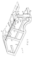
- the reference numeral 1 generally indicates a motor vehicle body including two sides, each of which comprises, in turn, a front pillar 2, two central pillars 3 and a rear pillar 4 connected to a lower beam 5 and an upper longitudinal beam 6.
- the rear pillar 4 is also connected to two rear crosspieces 7 and 8, with which it defines, together with a further pillar 4, an opening 9 which is closed by a hinged door 10.
- Each upper longitudinal beam 6 laterally delimits a roof 12 of the motor vehicle, and includes an outer profiled element 14 formed preferably by profiling and which remains partly in view in the finished motor vehicle, and an inner profiled element 24 firmly connected in known manner to the profiled element 14.
- a support device 15 is associated with the beams 6, for example, a closed container as illustrated in Figure 1 or, alternatively, a common open luggage rack.
- each profiled element 14 has an outer curved portion 16 which remains in view in the finished motor vehicle, an inner portion 17 having a flange 17a bent substantially at a right angle towards the other beam 6 and connected to a closure panel 12a of the roof 12, and a shaped intermediate portion 18 which upwardly delimits the associated beam 6.
- the upper portion 18 is so shaped as to define a longitudinal projection 19 formed integrally with the remaining part of the profiled element 6 and having a dovetail shape in cross section.
- the projection 19 includes two facing side walls 21 that converge towards each other and the profiled element 24, and a substantially flat intermediate wall 22 ( Figure 3), and is closed by a pair of plugs 19a each positively coupled in known way to an axial end portion of the projection 19 itself.
- connection unit 23 which includes, for each beam 6, an associated elongate body 25 which extends over the associated beam 6 and has a longitudinal channel 26 on the part facing the associated beam 6 itself.
- Each channel 26 has a transverse section complementary to the transverse section of the associated projection 19, and is engaged in an axially slidable manner by the associated projection 19 to define a sliding dovetailed coupling.
- Each body 25 includes a wall 27 which extends between the beams 6 in a position facing and spaced from the portion 17 with which it defines a cavity 27a, and terminates at a flange 28 bent at a right angle overlying a perimetral portion of the panel 12a.
- Each body 25 is attached to the associated profiled element 14 by means of associated screws 29, only one of which is visible in Figures 2 and 3, the shanks of which extend through respective holes formed in the wall 27 and engage respective threaded nuts or housings 31 which extend into the cavity 27a and are firmly connected to the portion 17 by means of brackets 32 which are also housed in the cavity 27a.
- the channel 26 has a cross section that is not perfectly complementary to that of the projection 19 so that there is transverse play, that is, parallel to the axis of the screws 29, and the body 25 is firmly connected to the beam 6 by a plurality of blind rivets extending through the projection 19 orthogonal to the screws 29.
- each body 25 also has a further longitudinal channel 34 which, in the particular example described, has an inverted T-shape in cross section, and forms the sliding guide for an associated slider which, in this particular case, is defined by a pair of runners 35 firmly connected to a structure of the device 15.
- Each runner 35 is axially slidable in the associated channel 34 under the thrust of an operator so as to enable the operator to move the device 15, in use, between a retracted position in which the device 15 lies in a position over the roof 12, and an extended position in which the support device 15 projects, partially cantilevered, rearwardly beyond the roof 12 and the bodies 25.
- the device 15 is lockable in both the aforesaid positions by means of reversible retaining members 36 ( Figure 1), known and not described in detail, associated with the bodies 25.
- the bodies 25 have no channels 34, and are connected to each other by a pair of cross-pieces.
- Each cross-piece defines an associated guide to which is slidingly coupled an associated slider which is slidingly connected to the device 15.
- the guide and slider assembly thus formed enables the device 15 to move transversely of the beams 6 to and from an extended position in which the device 15 projects laterally cantilevered beyond one of the associated beams 6.
- the device 25 can be moved towards and from its extended position in which it can easily be reached for loading and unloading operations by means of simple steps located at the rear of the motor vehicle, or directly attached to the device 15 itself, thus removing the risk of damaging the paintwork on the roof 12 or other parts of the motor vehicle body. Not only this, but if the device 15 is moved to a position projecting from a perimetral edge of the roof, it can be directly superimposed or brought alongside a bench or loading platform which is raised with respect to the surface on which the motor vehicle stands.
- the device 15 has at least one base panel and is in its extended position, it has the further function of providing a shelter, for example, from the rain, during loading/unloading operations through the rear door 10 or a side door.
- the device 15 can be removed from the roof 12 simply by sliding the runners 35 out from the bodies 25, which latter can be left mounted on the roof 12 without giving rise to aesthetic problems for the motor vehicle.
- the subsequent remounting of the device 15 is not particularly difficult, even for inexperienced people, particularly due to the fact that it can be effected very easily upon bringing the vehicle alongside a raised surface.
- the bodies 25 can have shapes and geometries different from those described and illustrated, for example, in order to adapt to different beams from those described; different guides from the guides 34 described can be provided and the different runners 35 carried by the support device 15.
Landscapes
- Engineering & Computer Science (AREA)
- Mechanical Engineering (AREA)
- Fittings On The Vehicle Exterior For Carrying Loads, And Devices For Holding Or Mounting Articles (AREA)
- Body Structure For Vehicles (AREA)
Applications Claiming Priority (2)
| Application Number | Priority Date | Filing Date | Title |
|---|---|---|---|
| ITTO980164 | 1998-02-27 | ||
| ITTO980164 IT1302078B1 (it) | 1998-02-27 | 1998-02-27 | Gruppo per l'accoppiamento di un dispositivo di supporto ad un tettodi un veicolo e tetto portante tale gruppo. |
Publications (2)
| Publication Number | Publication Date |
|---|---|
| EP0939006A2 true EP0939006A2 (de) | 1999-09-01 |
| EP0939006A3 EP0939006A3 (de) | 2000-05-31 |
Family
ID=11416498
Family Applications (1)
| Application Number | Title | Priority Date | Filing Date |
|---|---|---|---|
| EP99103581A Ceased EP0939006A3 (de) | 1998-02-27 | 1999-02-24 | Befestigungseinheit einer Tragevorrichtung auf dem Dach eines Kraftfahrzeuges und Dach mit solcher Einheit |
Country Status (2)
| Country | Link |
|---|---|
| EP (1) | EP0939006A3 (de) |
| IT (1) | IT1302078B1 (de) |
Cited By (3)
| Publication number | Priority date | Publication date | Assignee | Title |
|---|---|---|---|---|
| EP1153797A3 (de) * | 2000-05-09 | 2003-09-03 | Jac Products, Inc. | Fahrzeug- Dachprofilteilbefestigungsadapter |
| EP1527953A1 (de) * | 2003-11-03 | 2005-05-04 | Jac Products, Inc. | Bewegbarer Dachcontainer für Fahrzeug |
| CN108407726A (zh) * | 2017-02-07 | 2018-08-17 | 福特全球技术公司 | 具有一体式车顶架和附件附连组件的车顶结构 |
Citations (1)
| Publication number | Priority date | Publication date | Assignee | Title |
|---|---|---|---|---|
| DE3626479A1 (de) * | 1986-08-05 | 1988-02-18 | Jetbag Gmbh | Dachtraeger fuer dachrinnenlose kraftfahrzeuge |
Family Cites Families (3)
| Publication number | Priority date | Publication date | Assignee | Title |
|---|---|---|---|---|
| DE2712297A1 (de) * | 1977-03-21 | 1978-09-28 | Leo Th Prof Dr Re Zitzlsperger | Dachgepaecktraeger fuer fahrzeuge |
| FR2690117B1 (fr) * | 1992-04-17 | 1994-05-27 | Renault | Dispositif de fixation d'un support de porte-bagages sur le toit d'une carrosserie de vehicule automobile. |
| DE29602977U1 (de) * | 1996-02-20 | 1996-04-04 | Fabritius, Hans J., 48167 Münster | Autodachträger für Fahrräder |
-
1998
- 1998-02-27 IT ITTO980164 patent/IT1302078B1/it active IP Right Grant
-
1999
- 1999-02-24 EP EP99103581A patent/EP0939006A3/de not_active Ceased
Patent Citations (1)
| Publication number | Priority date | Publication date | Assignee | Title |
|---|---|---|---|---|
| DE3626479A1 (de) * | 1986-08-05 | 1988-02-18 | Jetbag Gmbh | Dachtraeger fuer dachrinnenlose kraftfahrzeuge |
Cited By (4)
| Publication number | Priority date | Publication date | Assignee | Title |
|---|---|---|---|---|
| EP1153797A3 (de) * | 2000-05-09 | 2003-09-03 | Jac Products, Inc. | Fahrzeug- Dachprofilteilbefestigungsadapter |
| EP1527953A1 (de) * | 2003-11-03 | 2005-05-04 | Jac Products, Inc. | Bewegbarer Dachcontainer für Fahrzeug |
| CN108407726A (zh) * | 2017-02-07 | 2018-08-17 | 福特全球技术公司 | 具有一体式车顶架和附件附连组件的车顶结构 |
| CN108407726B (zh) * | 2017-02-07 | 2023-08-08 | 福特全球技术公司 | 具有一体式车顶架和附件附连组件的车顶结构 |
Also Published As
| Publication number | Publication date |
|---|---|
| ITTO980164A1 (it) | 1999-08-27 |
| IT1302078B1 (it) | 2000-07-20 |
| EP0939006A3 (de) | 2000-05-31 |
Similar Documents
| Publication | Publication Date | Title |
|---|---|---|
| US11999309B2 (en) | Retractable step and side bar assembly for raised vehicle | |
| US5135274A (en) | Storage bumper and drawer | |
| US9789922B2 (en) | Modified door opening of a motorized vehicle for accommodating a ramp system and method thereof | |
| AU721168B2 (en) | Vehicle racking system | |
| US11623582B2 (en) | Hinge mount system for utility vehicle | |
| US10703286B2 (en) | Vehicle body structure | |
| DE102018131250B3 (de) | Verstauung der Kofferraumabdeckung im Frunk | |
| US20190275952A1 (en) | Hinge mount system for utility vehicle | |
| US20140183235A1 (en) | Roof rack leg | |
| JPH0757588B2 (ja) | 自動車の物品支持具および物品拘束クロスバーの可調整取付具 | |
| US20070039985A1 (en) | Roof rack concept for passenger vehicles, incorporating reconfigurable, multipurpose storage roof for improved aerodynamics and aesthetics | |
| US10406983B1 (en) | Vehicle body structure | |
| US11479068B2 (en) | Trailer coupling having a receiving sleeve | |
| EP0939006A2 (de) | Befestigungseinheit einer Tragevorrichtung auf dem Dach eines Kraftfahrzeuges und Dach mit solcher Einheit | |
| AU637983B2 (en) | Self-locking door trim for flush glass | |
| US10150420B2 (en) | Doors off storage | |
| US10632928B2 (en) | Vehicle body structure | |
| CZ280426B6 (cs) | Krycí uzávěr příčného nosníku střešního nosiče zavazadel | |
| EP1067000A3 (de) | Verstellbares Verdeck für ein Kraftfahrzeug | |
| EP1842727A1 (de) | Bewegliche Querstange | |
| JP2004168299A (ja) | 自動車のための取外し可能なルーフ | |
| US11299097B1 (en) | Deployable step | |
| US10046707B2 (en) | Door blocker for a vehicle | |
| EP1854664A2 (de) | T-förmige Befestigungsschiene und dazugehöriges Befestigungselement | |
| DE102010025213A1 (de) | Schutzvorrichtung für einen Fahrzeuginnenraum |
Legal Events
| Date | Code | Title | Description |
|---|---|---|---|
| PUAI | Public reference made under article 153(3) epc to a published international application that has entered the european phase |
Free format text: ORIGINAL CODE: 0009012 |
|
| AK | Designated contracting states |
Kind code of ref document: A2 Designated state(s): DE ES FR GB IT SE |
|
| AX | Request for extension of the european patent |
Free format text: AL;LT;LV;MK;RO;SI |
|
| PUAL | Search report despatched |
Free format text: ORIGINAL CODE: 0009013 |
|
| AK | Designated contracting states |
Kind code of ref document: A3 Designated state(s): AT BE CH CY DE DK ES FI FR GB GR IE IT LI LU MC NL PT SE |
|
| AX | Request for extension of the european patent |
Free format text: AL;LT;LV;MK;RO;SI |
|
| 17P | Request for examination filed |
Effective date: 20000912 |
|
| AKX | Designation fees paid |
Free format text: DE ES FR GB IT SE |
|
| 17Q | First examination report despatched |
Effective date: 20020717 |
|
| STAA | Information on the status of an ep patent application or granted ep patent |
Free format text: STATUS: THE APPLICATION HAS BEEN REFUSED |
|
| 18R | Application refused |
Effective date: 20030524 |