EP0939032B1 - Antriebs- und Lagerungsvorrichtung für die Verdrillscheiben der Umschnüreinrichtung von Abfall-Ballenpressen - Google Patents
Antriebs- und Lagerungsvorrichtung für die Verdrillscheiben der Umschnüreinrichtung von Abfall-Ballenpressen Download PDFInfo
- Publication number
- EP0939032B1 EP0939032B1 EP99102988A EP99102988A EP0939032B1 EP 0939032 B1 EP0939032 B1 EP 0939032B1 EP 99102988 A EP99102988 A EP 99102988A EP 99102988 A EP99102988 A EP 99102988A EP 0939032 B1 EP0939032 B1 EP 0939032B1
- Authority
- EP
- European Patent Office
- Prior art keywords
- drive
- twisting
- wheels
- wheel
- mounting device
- Prior art date
- Legal status (The legal status is an assumption and is not a legal conclusion. Google has not performed a legal analysis and makes no representation as to the accuracy of the status listed.)
- Expired - Lifetime
Links
- 239000000725 suspension Substances 0.000 title 1
- 230000005540 biological transmission Effects 0.000 claims description 4
- 239000002699 waste material Substances 0.000 claims description 3
- 238000003860 storage Methods 0.000 description 4
- 230000008901 benefit Effects 0.000 description 2
- 238000003825 pressing Methods 0.000 description 2
- 230000035508 accumulation Effects 0.000 description 1
- 238000009825 accumulation Methods 0.000 description 1
- 230000015572 biosynthetic process Effects 0.000 description 1
- 230000015556 catabolic process Effects 0.000 description 1
- 238000010276 construction Methods 0.000 description 1
- 238000005520 cutting process Methods 0.000 description 1
- 230000006378 damage Effects 0.000 description 1
- 238000011161 development Methods 0.000 description 1
- 230000018109 developmental process Effects 0.000 description 1
- 238000009826 distribution Methods 0.000 description 1
- 230000006872 improvement Effects 0.000 description 1
- 230000003993 interaction Effects 0.000 description 1
- 230000007246 mechanism Effects 0.000 description 1
- 210000000056 organ Anatomy 0.000 description 1
- 239000011343 solid material Substances 0.000 description 1
Images




Classifications
-
- B—PERFORMING OPERATIONS; TRANSPORTING
- B65—CONVEYING; PACKING; STORING; HANDLING THIN OR FILAMENTARY MATERIAL
- B65B—MACHINES, APPARATUS OR DEVICES FOR, OR METHODS OF, PACKAGING ARTICLES OR MATERIALS; UNPACKING
- B65B27/00—Bundling particular articles presenting special problems using string, wire, or narrow tape or band; Baling fibrous material, e.g. peat, not otherwise provided for
- B65B27/12—Baling or bundling compressible fibrous material, e.g. peat
-
- B—PERFORMING OPERATIONS; TRANSPORTING
- B65—CONVEYING; PACKING; STORING; HANDLING THIN OR FILAMENTARY MATERIAL
- B65B—MACHINES, APPARATUS OR DEVICES FOR, OR METHODS OF, PACKAGING ARTICLES OR MATERIALS; UNPACKING
- B65B13/00—Bundling articles
- B65B13/18—Details of, or auxiliary devices used in, bundling machines or bundling tools
- B65B13/24—Securing ends of binding material
- B65B13/28—Securing ends of binding material by twisting
-
- Y—GENERAL TAGGING OF NEW TECHNOLOGICAL DEVELOPMENTS; GENERAL TAGGING OF CROSS-SECTIONAL TECHNOLOGIES SPANNING OVER SEVERAL SECTIONS OF THE IPC; TECHNICAL SUBJECTS COVERED BY FORMER USPC CROSS-REFERENCE ART COLLECTIONS [XRACs] AND DIGESTS
- Y10—TECHNICAL SUBJECTS COVERED BY FORMER USPC
- Y10T—TECHNICAL SUBJECTS COVERED BY FORMER US CLASSIFICATION
- Y10T74/00—Machine element or mechanism
- Y10T74/19—Gearing
- Y10T74/19949—Teeth
- Y10T74/19963—Spur
- Y10T74/19972—Spur form
- Y10T74/19977—Antifriction
- Y10T74/19981—Roller
Definitions
- the invention relates to the preamble of Claim 1 to a drive and storage device primarily for a finished bale strapping station on waste balers with horizontal Press plate, in which several with a radial slot drill wheels for binding wire in one Bracket are stored and a common drive means temporarily for the purpose of wire twisting be rotated.
- twisting stations with slotted twist wheels have been known for several decades, and as a common drive on such bikes either revolving, endless drive chains or gear transmission systems used with corresponding external gears interact on the drill wheels.
- the present invention therefore has the task itself made, instead of the known fault-prone gear drives completely new drive and bearing system for the slotted Propose drill wheels, not just what the twine in the slotted twist washers make a significant improvement brings, but above all an extremely robust storage and Drive concept represents that even after a long period of operation and inevitably increased pollution is still working properly.
- rollers 3a a cylindrical Form base body, the lateral surface 3b with the Recesses 4a of the drive wheel 4 form-fitting fits together and its flat faces on both sides 3c as storage and management area in one Serve housing G, the latter 3c between the Housing G forming base and cover plate 6 and 7 the twisting station VD with sliding play on each other facing inner surfaces 6a and 7a are flush.
- the roles and their special design and Arrangement are thus storage and drive elements at the same time, what the previously so prone to failure gear systems with theirs for the wire inlet on the twisting discs 1 recessed in the slots 1c necessary Gears and split bearing bodies in a simple way makes redundant.
- roles 3a improve as can be seen from Fig.
Landscapes
- Engineering & Computer Science (AREA)
- Mechanical Engineering (AREA)
- Basic Packing Technique (AREA)
- Hydraulic Motors (AREA)
- Transmission Devices (AREA)
- Wire Processing (AREA)
- Spinning Or Twisting Of Yarns (AREA)
Description
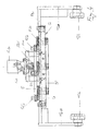
Die Zeichnungen zeigen im einzelnen in der
- Fig. 1
- die Draufsicht auf eine Ballenpresse im Bereich der Verdrillstation mit ausgeschwenkter Verdrilivorrichtung,
- Fig. 2
- das gleiche mit Verdrillvorrichtung in Betriebsstellung,
- Fig. 3
- in vergrößerter Darstellung die Verdrillelemente aus den Fig. 1 und 2 im Querschnitt
- Fig. 4
- ebenfalls vergrößert gegenüber Fig. 1 und 2 die gesamte Verdrillstation in Vorderansicht,
- Fig. 5
- eine Draufsicht auf die Verdrillelemente aus Fig. 4,
- Fig. 6
- eine der Verdrillstationen aus Fig. 5 als Einzelteil (vergrößert) und
- Fig. 7
- das Einzelteil "X" aus Fig. 3 (wiederum vergrößert).
- 1
- Verdrillscheibe
- 1a
- Schlitz
- 2
- Rad (für Anbringung der Verdrillscheibe)
- 2a
- Arm (sternförmig)
- 2b
- freies Arm-Ende
- 3
- Vertikalachse
- 3a
- Rolle (zylindrisch)
- 3b
- Mantelfläche
- 3c
- ebene Stirnseite
- 4
- Antriebsrad (für Pos. 2)
- 4a
- bogenförmige Aussparung
- 4b
- Außenumfang
- 5
- Schubkurbel
- 5'
- Stützkurbel
- 5a
- Drehzapfen, Kurbelzapfen
- 5b
- Antriebsmotor (hydraulisch)
- 6
- Grundplatte
- 6a
- Innenfläche
- 7
- Deckplatte
- 7a
- Innenfläche
- AK
- Antriebskurbel (von Pos. 5b zu 5)
- AN
- Ausnehmung an Pos. V
- AW
- Preßkasten-Außenwand
- BA
- Ballen
- BD
- Bindedraht
- DE
- Bindedraht-EinfUhrbereich
- DK
- Bindedraht-Durchschiebekopf
- DR
- Bindedraht-Rollenführung
- DV
- Bindedraht-Vorratsrolle
- DZ
- Bindedraht-Durchschiebezylinder
- G
- Gehäuse (der Verdrillelemente)
- GM
- Gehäusemittelteil (bzw. Führungsplatte zwischen Pos. 6 und 7)
- HD
- Hydraulik-Anschlußflansch
- KR
- Kopfrolle
- M
- Motorkonsole
- PK
- Preßkasten
- PR
- Preßrichtung
- RL
- Radial-Laufbahn bzw.
Abstützung der Lagerrollen 3a
- SA
- Schwenkarm von VD
- SH
- Schwenkzylinder-Halterung
- SL
- Schwenklager von VD
- SZ
- Schwenkzylinder von VD
- V
- Vollmaterialscheibe (anstelle von Pos. 2a, 2b)
- VD
- Verdrillstation
- VB
- Schwenkarm-Querverbindung
- VE
- Verdrillte Drahtenden
Claims (7)
- Antriebs- und Lagervorrichtung für eine Fertigballen-Umschnürstation vornehmlich an Abfall-Ballenpressen mit horizontal (PR) wirkender Pressplatte, mit einer Verdrillstation (VD), bei welcher mehrere mit einem Radialschlitz (1a) zur Aufnahme des Bindedrahtes (BD) versehene Drillräder (1,2) in einer Halterung (G) gelagert sind und über ein gemeinsames Antriebsmittel (5b, AK) zum Zwecke der Drahtverdrillung zeitweise in Drehung versetzt werden,
gekennzeichnet durch folgende in gegenseitiger Wirkverbindung miteinander stehende Ausgestaltungsmerkmale:a) die Räder (2) tragen geschlitzte Verdrillscheiben (1, 1a) und weisen mehrere, sich sternförmig nach außen erstreckende, Arme (2a) bzw. Lagerstellen auf, an denen bzw. deren freien Enden (2b) jeweils eine um eine senkrecht zur Radebene stehende Achse (3) frei drehbar gelagerte Rolle (3a) sitzt,b) jedem Sternrad (2, 2a) ist in gleicher Horizontalebene ein Antriebsrad (4) mit zu den Rollen (3a) formschlüssig korrespondierenden, bogenförmigen Aussparungen (4a) am Außenumfang (4b) zugeordnet,c) die Antriebsräder (4, 4a) sind zum Zwecke der Binde-Drahtverdrillung über ein motorisch zeitweise in Drehung versetztes, gemeinsames Antriebssystem (5, 5a, 5b) bewegungsgleich miteinander verbunden. - Antriebs- und Lagerungsvorrichtung nach Anspruch 1,
dadurch gekennzeichnet, dass die Rollen (3a) einen zylindrischen Grundkörper bilden, dessen Mantelfläche (3b) mit den Aussparungen (4a) des Antriebsrades (4) formschlüssig zusammenpaßt und dessen beidseitige, ebene Stirnflächen (3c) als Lager- und Führungsfläche in einem Gehäuse (G) dienen. - Antriebs- und Lagerungsvorrichtung nach den Ansprüchen 1 und 2,
dadurch gekennzeichnet, dass die Lager- und Führungsflächen (3c) zwischen der das Gehäuse (G) bildenden Grund- und Deckplatte (6 und 7) der Verdrillstation(VD) mit Gleitspiel an den aneinander zugekehrten Innenflächen (6a und 7a) bündig anliegen. - Antriebs- und Lagervorrichtung für eine Fertigballen-Umschnürstation vornehmlich an Abfall-Ballenpressen mit horizontal (PR) wirkender Pressplatte, mit einer Verdrillstation (VD), bei welcher mehrere mit einem Radialschlitz (1a) zur Aufnahme des Bindedrahtes (BD) versehene Drillräder (1,2) in einer Halterung (G) gelagert sind und über ein gemeinsames Antriebsmittel (5b, AK) zum Zwecke der Drahtverdrillung zeitweise in Drehung versetzt werden,
gekennzeichnet durch folgende in gegenseitiger Wirkverbindung miteinander stehende Ausgestaltungsmerkmale:a) die Räder (2) tragen geschlitzte Verdrillscheiben (1, 1a) und sind als kreisende, an ihren Oberflächen geschlossene Scheibe (V) mit entsprechend sternförmig angeordneten, radialen Ausnehmungen (AN) für die Anbringung von Lager- und Führungsrollen (3 - 3c) ausgebildet,b) jeder Scheibe (V) ist in gleicher Horizontalebene ein Antriebsrad (4) mit zu den Rollen (3a) formschlüssig korrespondierenden, bogenförmigen Aussparungen (4a) am Außenumfang (4b) zugeordnet,c) die Antriebsräder (4, 4a) sind zum Zwecke der Binde-Drahtverdrillung über ein motorisch zeitweise in Drehung versetztes, gemeinsames Antriebssystem (5, 5a, 5b) bewegungsgleich miteinander verbunden. - Antriebs- und Lagerungsvorrichtung nach einem oder mehreren der vorhergehenden Ansprüche,
dadurch gekennzeichnet, dass die gesamte Verdrillstation (VD) schwenkbar an einem Pressengehäuse gelagert ist. - Antriebs- und Lagerungsvorrichtung nach einem oder mehreren der vorhergehenden Ansprüche,
dadurch gekennzeichnet, dass das gemeinsame Antriebssystem für den Gleichlauf und die Positionierung der Antriebsräder (4) durch ein z. B. hydraulisch betätigtes Schubkurbelgetriebe (5, 5a, 5b, 5' ) gebildet wird. - Antriebs- und Lagerungsvorrichtung nach Anspruch 6,
dadurch gekennzeichnet, dass der hydraulische Antriebsmotor (5b) des Schubkurbelsystems (5, 5a) bei ungerader Radzahl (z. B. 3 Stück, 5 Stück usw.) auf dem mittleren Rad (4), bzw. bei einer geraden Zahl von Antriebsrädern (4) nahe der Systemmitte angeordnet ist.
Applications Claiming Priority (2)
| Application Number | Priority Date | Filing Date | Title |
|---|---|---|---|
| DE19808416 | 1998-02-28 | ||
| DE19808416A DE19808416C2 (de) | 1998-02-28 | 1998-02-28 | Antriebs- und Lagerungsvorrichtung für die Verdrillscheiben der Umschnüreinrichtung für Abfälle von Ballenpressen |
Publications (2)
| Publication Number | Publication Date |
|---|---|
| EP0939032A1 EP0939032A1 (de) | 1999-09-01 |
| EP0939032B1 true EP0939032B1 (de) | 2002-10-16 |
Family
ID=7859173
Family Applications (1)
| Application Number | Title | Priority Date | Filing Date |
|---|---|---|---|
| EP99102988A Expired - Lifetime EP0939032B1 (de) | 1998-02-28 | 1999-02-15 | Antriebs- und Lagerungsvorrichtung für die Verdrillscheiben der Umschnüreinrichtung von Abfall-Ballenpressen |
Country Status (5)
| Country | Link |
|---|---|
| US (1) | US6199475B1 (de) |
| EP (1) | EP0939032B1 (de) |
| JP (1) | JPH11278423A (de) |
| AT (1) | ATE226165T1 (de) |
| DE (2) | DE19808416C2 (de) |
Families Citing this family (11)
| Publication number | Priority date | Publication date | Assignee | Title |
|---|---|---|---|---|
| NL1017759C2 (nl) * | 2001-04-02 | 2002-10-10 | Syrcan B V | Werkwijze en inrichting voor het twisten van twee draadeinden. |
| US7389724B2 (en) * | 2004-12-17 | 2008-06-24 | Marathon Equipment Company | Waste baling method and apparatus |
| US7690402B2 (en) * | 2005-09-11 | 2010-04-06 | Machinefabriek Bollegraaf Appingedam B.V. | Method, an implement and a twister for tying together end portions of wire material extending around a bale |
| EP1785351A1 (de) | 2005-11-09 | 2007-05-16 | Machinefabriek Bollegraaf Appingedam B.V. | Verfahren, Vorrichtung und Verdriller um Endteile eines ballenumschlingenden Drahts zusammenzubinden |
| DE202012004276U1 (de) | 2012-05-02 | 2013-08-06 | Hermann Schwelling | Kanalballenpresse |
| DE102012008554A1 (de) | 2012-05-02 | 2013-11-07 | Hermann Schwelling | Kanalballenpresse |
| SMT202400349T1 (it) | 2015-07-22 | 2024-11-15 | Max Co Ltd | Bobina per macchina legatrice |
| DE202018101650U1 (de) * | 2018-03-23 | 2019-06-27 | Rasspe Systemtechnik GmbH | Garnknoteranordnung zum Knoten von Garn und Ballenpressvorrichtung |
| CN112192424B (zh) * | 2020-10-13 | 2021-10-29 | 深圳长城开发精密技术有限公司 | 一种硬盘基片装载游星轮 |
| CN112660474A (zh) * | 2021-01-15 | 2021-04-16 | 柳州钢铁股份有限公司 | 棒材成品打包线头压平装置 |
| CN118832525B (zh) * | 2024-09-23 | 2024-11-22 | 北京特思迪半导体设备有限公司 | 一种游星轮外圈升降闪停装置以及外圈驱动系统 |
Family Cites Families (8)
| Publication number | Priority date | Publication date | Assignee | Title |
|---|---|---|---|---|
| US860536A (en) * | 1906-11-24 | 1907-07-16 | Robert W Ellingham | Roller-pinion. |
| US1040278A (en) * | 1912-01-11 | 1912-10-08 | Roy A Collins | Automatic baling-machine. |
| US3387556A (en) * | 1966-03-25 | 1968-06-11 | Devco Inc | Snare-type wire binding machine |
| SE7708581L (sv) * | 1976-07-28 | 1978-01-29 | Dobson Park Eng | Knytmekanism for staltrad och liknande |
| DE2656457C3 (de) * | 1976-12-14 | 1981-04-16 | Lindemann Maschinenfabrik GmbH, 4000 Düsseldorf | Ballenpresse |
| DE3247147A1 (de) * | 1982-01-25 | 1983-07-28 | Lindemann Maschinenfabrik GmbH, 4000 Düsseldorf | Vorrichtung zum umschnueren von ballen in einer ballenpresse |
| DE3544773A1 (de) * | 1985-12-18 | 1987-06-25 | Lindemann Maschfab Gmbh | Vorrichtung zum umschnueren von ballen |
| US4718336A (en) * | 1986-10-22 | 1988-01-12 | Cives Corp. | Modular automatic bale tier |
-
1998
- 1998-02-28 DE DE19808416A patent/DE19808416C2/de not_active Expired - Fee Related
-
1999
- 1999-02-15 AT AT99102988T patent/ATE226165T1/de not_active IP Right Cessation
- 1999-02-15 EP EP99102988A patent/EP0939032B1/de not_active Expired - Lifetime
- 1999-02-15 DE DE59903070T patent/DE59903070D1/de not_active Expired - Fee Related
- 1999-02-26 JP JP11050830A patent/JPH11278423A/ja active Pending
- 1999-02-26 US US09/259,032 patent/US6199475B1/en not_active Expired - Fee Related
Also Published As
| Publication number | Publication date |
|---|---|
| US6199475B1 (en) | 2001-03-13 |
| DE19808416A1 (de) | 1999-09-23 |
| EP0939032A1 (de) | 1999-09-01 |
| ATE226165T1 (de) | 2002-11-15 |
| DE59903070D1 (de) | 2002-11-21 |
| JPH11278423A (ja) | 1999-10-12 |
| DE19808416C2 (de) | 1999-12-23 |
Similar Documents
| Publication | Publication Date | Title |
|---|---|---|
| DE69607790T2 (de) | Mahlvorrichtung für Mehl | |
| EP0316553B1 (de) | Antrieb für einen Drehteller in einer Etikettiermaschine für Flaschen | |
| DD200850A5 (de) | Uebertragungsvorrichtung fuer staebchenfoermige artikel | |
| DE19808416C2 (de) | Antriebs- und Lagerungsvorrichtung für die Verdrillscheiben der Umschnüreinrichtung für Abfälle von Ballenpressen | |
| DE3801728A1 (de) | Rollenmuehle | |
| DE10044370C1 (de) | Transportrolle | |
| DE69803238T2 (de) | Abrichtmaschine | |
| DE3524601C2 (de) | ||
| DE2908159C2 (de) | ||
| DE2843244A1 (de) | Walzenstrasse mit zwei walzgeruestgruppen in blockform-anordnung | |
| DE2128929B2 (de) | Walzenmühle | |
| DE60009016T2 (de) | Vorrichtung zur mechanischen Reinigung von Draht für die Herstellung von gezogenen Metalldrähten | |
| DE3315033A1 (de) | Aufnahmetrommel fuer gemaehtes erntegut | |
| DE3642741A1 (de) | Exzenterschleifer | |
| DE3206704C2 (de) | Entnahme- und Übergabevorrichtung für Etiketten oder dergl. | |
| DE60118011T2 (de) | Fertingungsstrasse für nahrungsmittelprodukte | |
| DE2602392C2 (de) | Tangentialriemenantrieb für Spinnrotoren | |
| DE3933804C2 (de) | ||
| DE3121583A1 (de) | Abbeermaschine | |
| DD220542A1 (de) | Werkzeugspeicher fuer automatische werkzeugwechseleinrichtng | |
| DE2704684C3 (de) | ||
| DE102007023460B4 (de) | Streckwerk für eine Spinnmaschine | |
| DE19736102C2 (de) | Zweiwalzen-Biegemaschine | |
| EP1256398B1 (de) | Querwalzmaschine | |
| DE69503311T2 (de) | Antriebsvorrichtung für hin- und hergehende Messerkästen mit Kurbeltrieb |
Legal Events
| Date | Code | Title | Description |
|---|---|---|---|
| PUAI | Public reference made under article 153(3) epc to a published international application that has entered the european phase |
Free format text: ORIGINAL CODE: 0009012 |
|
| AK | Designated contracting states |
Kind code of ref document: A1 Designated state(s): AT DE DK ES FR GB SE |
|
| AX | Request for extension of the european patent |
Free format text: AL;LT;LV;MK;RO;SI |
|
| 17P | Request for examination filed |
Effective date: 20000229 |
|
| AKX | Designation fees paid |
Free format text: AT DE DK ES FR GB SE |
|
| RBV | Designated contracting states (corrected) |
Designated state(s): AT DE ES FR GB IT SE |
|
| 17Q | First examination report despatched |
Effective date: 20001103 |
|
| GRAG | Despatch of communication of intention to grant |
Free format text: ORIGINAL CODE: EPIDOS AGRA |
|
| GRAG | Despatch of communication of intention to grant |
Free format text: ORIGINAL CODE: EPIDOS AGRA |
|
| GRAH | Despatch of communication of intention to grant a patent |
Free format text: ORIGINAL CODE: EPIDOS IGRA |
|
| RBV | Designated contracting states (corrected) |
Designated state(s): AT DE DK ES FR GB SE |
|
| GRAH | Despatch of communication of intention to grant a patent |
Free format text: ORIGINAL CODE: EPIDOS IGRA |
|
| GRAA | (expected) grant |
Free format text: ORIGINAL CODE: 0009210 |
|
| AK | Designated contracting states |
Kind code of ref document: B1 Designated state(s): AT DE DK ES FR GB SE |
|
| REF | Corresponds to: |
Ref document number: 226165 Country of ref document: AT Date of ref document: 20021115 Kind code of ref document: T |
|
| REG | Reference to a national code |
Ref country code: GB Ref legal event code: FG4D Free format text: NOT ENGLISH |
|
| GBT | Gb: translation of ep patent filed (gb section 77(6)(a)/1977) |
Effective date: 20021016 |
|
| REF | Corresponds to: |
Ref document number: 59903070 Country of ref document: DE Date of ref document: 20021121 |
|
| PG25 | Lapsed in a contracting state [announced via postgrant information from national office to epo] |
Ref country code: SE Free format text: LAPSE BECAUSE OF FAILURE TO SUBMIT A TRANSLATION OF THE DESCRIPTION OR TO PAY THE FEE WITHIN THE PRESCRIBED TIME-LIMIT Effective date: 20030116 Ref country code: DK Free format text: LAPSE BECAUSE OF FAILURE TO SUBMIT A TRANSLATION OF THE DESCRIPTION OR TO PAY THE FEE WITHIN THE PRESCRIBED TIME-LIMIT Effective date: 20030116 |
|
| ET | Fr: translation filed | ||
| PG25 | Lapsed in a contracting state [announced via postgrant information from national office to epo] |
Ref country code: AT Free format text: LAPSE BECAUSE OF NON-PAYMENT OF DUE FEES Effective date: 20030215 |
|
| PG25 | Lapsed in a contracting state [announced via postgrant information from national office to epo] |
Ref country code: ES Free format text: LAPSE BECAUSE OF FAILURE TO SUBMIT A TRANSLATION OF THE DESCRIPTION OR TO PAY THE FEE WITHIN THE PRESCRIBED TIME-LIMIT Effective date: 20030429 |
|
| PLBE | No opposition filed within time limit |
Free format text: ORIGINAL CODE: 0009261 |
|
| STAA | Information on the status of an ep patent application or granted ep patent |
Free format text: STATUS: NO OPPOSITION FILED WITHIN TIME LIMIT |
|
| 26N | No opposition filed |
Effective date: 20030717 |
|
| PGFP | Annual fee paid to national office [announced via postgrant information from national office to epo] |
Ref country code: DE Payment date: 20090219 Year of fee payment: 11 |
|
| PGFP | Annual fee paid to national office [announced via postgrant information from national office to epo] |
Ref country code: GB Payment date: 20090213 Year of fee payment: 11 |
|
| PGFP | Annual fee paid to national office [announced via postgrant information from national office to epo] |
Ref country code: FR Payment date: 20090220 Year of fee payment: 11 |
|
| GBPC | Gb: european patent ceased through non-payment of renewal fee |
Effective date: 20100215 |
|
| REG | Reference to a national code |
Ref country code: FR Ref legal event code: ST Effective date: 20101029 |
|
| PG25 | Lapsed in a contracting state [announced via postgrant information from national office to epo] |
Ref country code: FR Free format text: LAPSE BECAUSE OF NON-PAYMENT OF DUE FEES Effective date: 20100301 |
|
| PG25 | Lapsed in a contracting state [announced via postgrant information from national office to epo] |
Ref country code: DE Free format text: LAPSE BECAUSE OF NON-PAYMENT OF DUE FEES Effective date: 20100901 |
|
| PG25 | Lapsed in a contracting state [announced via postgrant information from national office to epo] |
Ref country code: GB Free format text: LAPSE BECAUSE OF NON-PAYMENT OF DUE FEES Effective date: 20100215 |