EP0939049A2 - Dispositif pour prélever une feuille d'essai dans un appareil de sortie d'une machine à imprimer des feuilles - Google Patents
Dispositif pour prélever une feuille d'essai dans un appareil de sortie d'une machine à imprimer des feuilles Download PDFInfo
- Publication number
- EP0939049A2 EP0939049A2 EP99102141A EP99102141A EP0939049A2 EP 0939049 A2 EP0939049 A2 EP 0939049A2 EP 99102141 A EP99102141 A EP 99102141A EP 99102141 A EP99102141 A EP 99102141A EP 0939049 A2 EP0939049 A2 EP 0939049A2
- Authority
- EP
- European Patent Office
- Prior art keywords
- sheet
- stop
- stack
- moved
- auxiliary
- Prior art date
- Legal status (The legal status is an assumption and is not a legal conclusion. Google has not performed a legal analysis and makes no representation as to the accuracy of the status listed.)
- Granted
Links
Images

Classifications
-
- B—PERFORMING OPERATIONS; TRANSPORTING
- B65—CONVEYING; PACKING; STORING; HANDLING THIN OR FILAMENTARY MATERIAL
- B65H—HANDLING THIN OR FILAMENTARY MATERIAL, e.g. SHEETS, WEBS, CABLES
- B65H29/00—Delivering or advancing articles from machines; Advancing articles to or into piles
- B65H29/58—Article switches or diverters
- B65H29/585—Article switches or diverters taking samples from the main stream
-
- B—PERFORMING OPERATIONS; TRANSPORTING
- B65—CONVEYING; PACKING; STORING; HANDLING THIN OR FILAMENTARY MATERIAL
- B65H—HANDLING THIN OR FILAMENTARY MATERIAL, e.g. SHEETS, WEBS, CABLES
- B65H29/00—Delivering or advancing articles from machines; Advancing articles to or into piles
- B65H29/02—Delivering or advancing articles from machines; Advancing articles to or into piles by mechanical grippers engaging the leading edge only of the articles
- B65H29/04—Delivering or advancing articles from machines; Advancing articles to or into piles by mechanical grippers engaging the leading edge only of the articles the grippers being carried by endless chains or bands
- B65H29/041—Delivering or advancing articles from machines; Advancing articles to or into piles by mechanical grippers engaging the leading edge only of the articles the grippers being carried by endless chains or bands and introducing into a pile
-
- B—PERFORMING OPERATIONS; TRANSPORTING
- B65—CONVEYING; PACKING; STORING; HANDLING THIN OR FILAMENTARY MATERIAL
- B65H—HANDLING THIN OR FILAMENTARY MATERIAL, e.g. SHEETS, WEBS, CABLES
- B65H2404/00—Parts for transporting or guiding the handled material
- B65H2404/70—Other elements in edge contact with handled material, e.g. registering, orientating, guiding devices
- B65H2404/72—Stops, gauge pins, e.g. stationary
- B65H2404/722—Stops, gauge pins, e.g. stationary movable in operation
-
- B—PERFORMING OPERATIONS; TRANSPORTING
- B65—CONVEYING; PACKING; STORING; HANDLING THIN OR FILAMENTARY MATERIAL
- B65H—HANDLING THIN OR FILAMENTARY MATERIAL, e.g. SHEETS, WEBS, CABLES
- B65H2404/00—Parts for transporting or guiding the handled material
- B65H2404/70—Other elements in edge contact with handled material, e.g. registering, orientating, guiding devices
- B65H2404/72—Stops, gauge pins, e.g. stationary
- B65H2404/725—Stops, gauge pins, e.g. stationary retractable
-
- B—PERFORMING OPERATIONS; TRANSPORTING
- B65—CONVEYING; PACKING; STORING; HANDLING THIN OR FILAMENTARY MATERIAL
- B65H—HANDLING THIN OR FILAMENTARY MATERIAL, e.g. SHEETS, WEBS, CABLES
- B65H2407/00—Means not provided for in groups B65H2220/00 – B65H2406/00 specially adapted for particular purposes
- B65H2407/10—Safety means, e.g. for preventing injuries or illegal operations
-
- B—PERFORMING OPERATIONS; TRANSPORTING
- B65—CONVEYING; PACKING; STORING; HANDLING THIN OR FILAMENTARY MATERIAL
- B65H—HANDLING THIN OR FILAMENTARY MATERIAL, e.g. SHEETS, WEBS, CABLES
- B65H2801/00—Application field
- B65H2801/03—Image reproduction devices
- B65H2801/21—Industrial-size printers, e.g. rotary printing press
Definitions
- the invention relates to a device for taking samples on a delivery of a sheet-fed printing press with a retractable into the sheet delivery path above the sheet stack Bow support and a bow stop for the front edge the sheet, which consists of one attached to the sheet stack Stop position in a sample sheet enabling the removal of test sheets Removal position is movable.
- Devices for taking samples are different Design known. They are used during the Printing company to take test sheets to check the To enable print results.
- an auxiliary stop is used to take out test sheets swung in and on the one preceding the sample sheet Predecessor arch offset, creating the top arch be fixed on the delivery pile.
- blowers blow into the delivery pile and lift the incoming test sheet over the auxiliary stop away.
- the front stops are folded back so that the test sheet no longer reaches this and the kinetic energy of the sample sheet over the leading edge of the stack floor plan is promoted.
- the invention has for its object a device to create sample sheets of the type mentioned at the beginning, which is characterized by a low construction cost and a simple Controllability distinguishes and which is a simple and enables safe sample sheet removal.
- this object is achieved in that the Sheet stop in a second set down from the sheet stack Stop position is movable and the sheet conveyance is so adjustable that the test sheet with his Leading edge to the one set down by the sheet stack Bow stop is promoted and that the bow stop from the second stop position in the removal position is movable.
- the device according to the invention With the device according to the invention, it is without complex Auxiliary devices and complicated controls possible, with the sample sheet in a precisely defined position front edge of the sheet protruding from the front edge of the stack to file without the risk of damaging the There is a leading edge of the sheet. According to the arch stop procedure the sample sheets can then be taken to a removal position grasped at precisely defined point and from the sheet stack be removed. This precisely defined area of intervention can be secured with safety devices so that none There is a risk of injury. Also grasping and removing of test sheets with the help of mechanical devices due to the precisely defined position of the front edge of the test sheet possible.
- the movement of the bow stop into the second stop position can according to the invention by parallel displacement and / or by a rotary movement.
- a Rotary motion can be beneficial if the bow stop two stop surfaces arranged at an angle to each other has, the one stop surface in one at the stop position and the other stop surface in the second parked from the sheet stack Stop position is effective.
- the can mentioned task can also be solved in that a second stop position set off from the sheet stack an auxiliary stop is arranged to which the test sheet can be applied with their front edge when the sheet stop parked behind the auxiliary stop of the sheet stack.
- a second stop position set off from the sheet stack an auxiliary stop is arranged to which the test sheet can be applied with their front edge when the sheet stop parked behind the auxiliary stop of the sheet stack.
- auxiliary stop can be made according to a proposal the invention consist in that the auxiliary stop by a protective device can be moved into the removal position is that in the sheet delivery path in the engagement area for the Sample sheet removal is retractable over the sheet stack.
- Auxiliary stop can be from a rotatably mounted be formed two-armed lever, one of which is a lever arm through the protective device when entering the sheet delivery path is pivoted.
- a sheet stack 1 is shown, which is in a Boom of a sheet printing machine, not shown located and in the usual way by means of a sheet conveyor, for example a chain gripper system in printed sheets can be fed continuously from above.
- the Feeding takes place in such a way that the sheet in the direction indicated by an arrow 2 using Grippers transported over the sheet stack 1 and then on be released at a certain point.
- Supported by Blowers then drop the sheets onto the sheet stack 1, being due to a from the horizontal conveying movement resulting and possibly by braking devices reduced movement impulse with its leading edge knock against a bow stop 3.
- the bow stop 3 is attached to a shaft 4 which is rotatable on a Carriage 5 is mounted.
- the carriage 5 is in a guide 6 horizontal and perpendicular to that through the leading edges the arc formed front stacking surface 7 out and can be moved with the help of a lifting cylinder 8 the bow stop 3 from a first stop position I in to move a second stop position II or vice versa.
- the stop position I which is responsible for the formation of the Sheet stack 1 is determined, the sheet stop 3 to the front stacking surface 7 of the sheet stack 1 is employed.
- the sheet stop is used 3 with the help of the lifting cylinder 8 in the stop position II proceed in which the sheet stop 3 in a distance from the front stacking surface 7.
- the sheet conveyor is set so that the supplied sample sheet 9 is sufficient receives a large movement impulse in the conveying direction so that it with its front edge until it hits the in the Stop position II located sheet stop 3 moves becomes.
- a sheet holder is 10 in the sheet filing path above the sheet stack 1 retracted, which holds back the incoming follow-up sheets. The holding up of the following sheets cannot be done by shown blowing devices are supported.
- the stop position II set off from the sheet stack 1 can also in the embodiment of Figure 1 without a parallel shift simply by rotating the Bow stop 3, in the drawing counterclockwise, reach through a defined angle so that the Construction work for the slide guide and its operation can be omitted.
- the rotation of the arch stop 3 are here however, there are narrow limits, as the rotation also the stop surface tends and its impact loses if the angle of inclination the angle of friction of the Friction pairing of printing material contact surface exceeds. Without measures to increase friction can be achieved with this construction simpler variant, therefore only a smaller projection of the Reach the test sheet.
- the Bow stop 3 two stop surfaces 31, 32, which are parallel are arranged to the shaft axis and an angle of enclose about 110 °.
- the stop surface 31 has one greater distance from the shaft 4 than the stop surface 32.
- the shaft 4 of the bow stop is in contrast to the embodiment 1 rotatable in a fixed bearing stored.
- the sheet stack 1 In the stop position I for the normal storage of sheets the sheet stack 1 is the sheet stop 3 with his Stop surface 31 made to the sheet stack 1.
- the Stop surface 32 closes at the lower end of the Stop surface 31, the through the two stop surfaces 31, 32 formed edge approximately in the same horizontal
- the plane lies like the axis of rotation of the shaft 4.
- the stop surface 32 of this stop position II of the bow stop 3 in one Distance from the front stacking surface 7, so that to the Stop surface 32 abutting test sheet 9 with its front Edge area protrudes beyond the stacking surface 7.
- the follow-up curves are the same as in the previous embodiment held up by driving out a bow holder 10.
- the shaft 4 with the bow stop 3 again counterclockwise by 90 ° into the removal position III rotated, in which the protruding edge area of the sample sheet 9 and the sample sheet 9 removed can be.
- the bow stop 3 turns clockwise turned back to the stop position I and the Bow holder retracted.
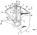
- auxiliary stop 11 which has the shape of a two-armed Has lever and attached to a bracket 12 to the shaft 4 parallel axis 13 pivotally mounted is.
- the auxiliary stop 11 In its stop position shown in the drawing II is the auxiliary stop 11 with its stop surface 14 at a suitable distance parallel to the front stacking surface 7 aligned, the shorter lever arm 111 of the auxiliary stop 11 from a leg spring, not shown pressed against a stop 15 on the carrier 12 becomes.
- the auxiliary stop is opposite the sheet stop 3 11 offset in the axial direction, so that the sheet stop 3 can be pivoted past the auxiliary stop 11.
- a bow holder and protection against tampering serving device 16 which consists of a curved, over the sheet width 17 extends beyond the format, its ends outside the format on supports 18 attached and by means of pins 19 in the boom to one Shaft 4 parallel axis are pivotally mounted.
- the sheet 17 has an opening 20, through which the short lever arm 111 of the auxiliary stop 11 projects.
- the carrier 12 is also in an opening of the Sheet 17 arranged in the circumferential direction extends to pivot movement of the device 16 enable.
- the sheet stop With a normal sheet delivery, the sheet stop is located 3, the auxiliary stop 11 and the device 16 in the in the drawing shown with solid lines Positions. If a sample sheet is to be taken, then first the bow stop 3 by turning the shaft 4 of the sheet stack 1 is parked and on the auxiliary stop 11 over to the dashed position II pivoted. In this position of the sheet stop 3 is the Space between the sheet stack 1 and the auxiliary stop 11 free, so that a now following and with sufficient movement impulse fed sample sheet 9 over the front Stack edge 7 moved out and with its front edge abuts the auxiliary stop 11.
- the arch stop 3 Due to position II the arch stop 3 is here for security reasons Access to the incoming sample sheet (s) not possible because the bow stop 3 has a lot in small Spaced parallel fingers and locks in connection with the device 16 in this position the area of intervention for sampling.
- the Device 16 After placing a sample sheet 9 or more, the Device 16 with the help of a not shown Drive in the removal position shown in dashed lines III pivoted over the sheet stack 1, whereby the subsequent sheet 21 held up by the sheet 17.
Landscapes
- Engineering & Computer Science (AREA)
- Mechanical Engineering (AREA)
- Pile Receivers (AREA)
- Sheets, Magazines, And Separation Thereof (AREA)
- Supply, Installation And Extraction Of Printed Sheets Or Plates (AREA)
- Separation, Sorting, Adjustment, Or Bending Of Sheets To Be Conveyed (AREA)
- Sampling And Sample Adjustment (AREA)
Priority Applications (1)
| Application Number | Priority Date | Filing Date | Title |
|---|---|---|---|
| EP01118391A EP1149791B1 (fr) | 1998-02-27 | 1999-02-03 | Dispositif pour prélever une feuille d'essai dans un appareil de sortie d'une machine à imprimer des feuilles |
Applications Claiming Priority (2)
| Application Number | Priority Date | Filing Date | Title |
|---|---|---|---|
| DE19808310A DE19808310A1 (de) | 1998-02-27 | 1998-02-27 | Vorrichtung zur Probebogenentnahme an einem Ausleger einer Bogendruckmaschine |
| DE19808310 | 1998-02-27 |
Related Child Applications (1)
| Application Number | Title | Priority Date | Filing Date |
|---|---|---|---|
| EP01118391A Division EP1149791B1 (fr) | 1998-02-27 | 1999-02-03 | Dispositif pour prélever une feuille d'essai dans un appareil de sortie d'une machine à imprimer des feuilles |
Publications (3)
| Publication Number | Publication Date |
|---|---|
| EP0939049A2 true EP0939049A2 (fr) | 1999-09-01 |
| EP0939049A3 EP0939049A3 (fr) | 2000-06-28 |
| EP0939049B1 EP0939049B1 (fr) | 2002-04-17 |
Family
ID=7859110
Family Applications (2)
| Application Number | Title | Priority Date | Filing Date |
|---|---|---|---|
| EP99102141A Expired - Lifetime EP0939049B1 (fr) | 1998-02-27 | 1999-02-03 | Dispositif pour prélever une feuille d'essai dans un appareil de sortie d'une machine à imprimer des feuilles |
| EP01118391A Expired - Lifetime EP1149791B1 (fr) | 1998-02-27 | 1999-02-03 | Dispositif pour prélever une feuille d'essai dans un appareil de sortie d'une machine à imprimer des feuilles |
Family Applications After (1)
| Application Number | Title | Priority Date | Filing Date |
|---|---|---|---|
| EP01118391A Expired - Lifetime EP1149791B1 (fr) | 1998-02-27 | 1999-02-03 | Dispositif pour prélever une feuille d'essai dans un appareil de sortie d'une machine à imprimer des feuilles |
Country Status (4)
| Country | Link |
|---|---|
| EP (2) | EP0939049B1 (fr) |
| JP (1) | JP4166895B2 (fr) |
| AT (2) | ATE264260T1 (fr) |
| DE (3) | DE19808310A1 (fr) |
Families Citing this family (8)
| Publication number | Priority date | Publication date | Assignee | Title |
|---|---|---|---|---|
| DE10129894A1 (de) | 2000-07-28 | 2002-05-02 | Heidelberger Druckmasch Ag | Ausleger für eine flächige Bedruckstoffe verarbeitende Maschine, insbesondere eine Druckmaschine |
| DE10244698B4 (de) * | 2002-09-24 | 2011-02-03 | Manroland Ag | Non-Stop-Einrichtung für einen Bogenausleger |
| US7007948B2 (en) | 2003-02-28 | 2006-03-07 | Canon Kabushiki Kaisha | Sheet stacking/aligning apparatus, sheet handling apparatus, and image forming apparatus |
| DE10326622A1 (de) * | 2003-06-13 | 2005-01-05 | Koenig & Bauer Ag | Vorrichtung zur Probebogenentnahme im Ausleger einer bogenverarbeitenden Maschine |
| DE10354673A1 (de) * | 2003-11-22 | 2005-06-16 | Koenig & Bauer Ag | Vorrichtung zum Aussondern von Bogen aus dem Ausleger einer Bogenrotationsdruckmaschine |
| JP2006047451A (ja) | 2004-08-02 | 2006-02-16 | Kawai Musical Instr Mfg Co Ltd | 電子楽器 |
| DE102009046987B4 (de) | 2009-11-23 | 2023-06-01 | Koenig & Bauer Ag | Auslage einer bogenverarbeitenden Maschine mit einem Bogen aufnehmenden Auslagestapel und ein Verfahren zum Stapelwechsel |
| TWI783345B (zh) * | 2020-02-13 | 2022-11-11 | 大陸商博斯特(上海)有限公司 | 用於將板材堆儲存於一轉換機中之裝置及轉換機 |
Family Cites Families (6)
| Publication number | Priority date | Publication date | Assignee | Title |
|---|---|---|---|---|
| DE2900645C3 (de) * | 1979-01-09 | 1981-10-15 | Rotaprint Gmbh, 1000 Berlin | Bogenausleger mit einer Vorrichtung zur Probebogenentnahme |
| DD202850A1 (de) * | 1981-12-03 | 1983-10-05 | Karl Marx | Einrichtung zur bogenablage und probebogenentnahme in bogenauslagen |
| DE4207107C1 (fr) * | 1992-03-06 | 1993-06-09 | Man Roland Druckmaschinen Ag, 6050 Offenbach, De | |
| DE4213032A1 (de) * | 1992-04-21 | 1993-10-28 | Kba Planeta Ag | Einrichtung zur Probebogenentnahme in Auslagen von Druckmaschinen |
| DE9305757U1 (de) * | 1993-04-16 | 1993-08-05 | Kba-Planeta Ag, 01445 Radebeul | Entnahmeeinrichtung für steife Bedruckstoffe |
| DE19808309A1 (de) * | 1998-02-27 | 1999-09-02 | Roland Man Druckmasch | Vorrichtung zur Probebogenentnahme an einem Ausleger einer Bogendruckmaschine |
-
1998
- 1998-02-27 DE DE19808310A patent/DE19808310A1/de not_active Withdrawn
-
1999
- 1999-02-03 AT AT01118391T patent/ATE264260T1/de not_active IP Right Cessation
- 1999-02-03 AT AT99102141T patent/ATE216348T1/de not_active IP Right Cessation
- 1999-02-03 DE DE59909207T patent/DE59909207D1/de not_active Expired - Lifetime
- 1999-02-03 EP EP99102141A patent/EP0939049B1/fr not_active Expired - Lifetime
- 1999-02-03 EP EP01118391A patent/EP1149791B1/fr not_active Expired - Lifetime
- 1999-02-03 DE DE59901232T patent/DE59901232D1/de not_active Expired - Lifetime
- 1999-02-26 JP JP05116099A patent/JP4166895B2/ja not_active Expired - Fee Related
Also Published As
| Publication number | Publication date |
|---|---|
| EP1149791A3 (fr) | 2001-11-07 |
| DE59909207D1 (de) | 2004-05-19 |
| ATE216348T1 (de) | 2002-05-15 |
| DE59901232D1 (de) | 2002-05-23 |
| DE19808310A1 (de) | 1999-09-02 |
| EP1149791B1 (fr) | 2004-04-14 |
| EP1149791A2 (fr) | 2001-10-31 |
| EP0939049A3 (fr) | 2000-06-28 |
| ATE264260T1 (de) | 2004-04-15 |
| JP4166895B2 (ja) | 2008-10-15 |
| JPH11291452A (ja) | 1999-10-26 |
| EP0939049B1 (fr) | 2002-04-17 |
Similar Documents
| Publication | Publication Date | Title |
|---|---|---|
| DE3145491C2 (fr) | ||
| DE2535123B2 (de) | Vorrichtung zum Umwenden von FlachmaterialstUcken KK Tomoku, Otaru, Hokkaido (Japan) | |
| DE2553518A1 (de) | Blattwende- und ablegevorrichtung | |
| DE2633183C2 (de) | Wendevorrichtung an einer von Schön- auf Schön- und Widerdruck umstellbaren Bogenrotationsmaschine | |
| DE2657694C3 (de) | Spulenwechselvorrichtung an einer Offenendspinnmaschine | |
| DE19519374A1 (de) | Vorrichtung zur automatischen Bogenaussonderung im Ausleger einer Bogenrotationsdruckmaschine | |
| DE3603285A1 (de) | Zusammentragmaschine | |
| CH625481A5 (fr) | ||
| DE10319845A1 (de) | Verstellbare Greifvorrichtung für verstellbare Bogenaufnahmetaschen | |
| EP0897890B1 (fr) | Procédé et dispositif pour produire un courant de produits tournés avec une pince de préhension de coin | |
| DE10147134B4 (de) | Stackerriemen mit geschalteten Einzahlkassetten | |
| DE605130C (de) | Vorrichtung zum Aussondern einzelner Bogen in der Auslage von Druckmaschinen o. dgl.von Hand | |
| EP0939049B1 (fr) | Dispositif pour prélever une feuille d'essai dans un appareil de sortie d'une machine à imprimer des feuilles | |
| DE19507370C2 (de) | Bogenausleger für eine Druckmaschine | |
| EP0967164B1 (fr) | Méthode et dispositif pour alimenter des feuilles imprimées et pliées à cheval sur une section d'assemblage | |
| DE102022118978A1 (de) | Auslage und Verfahren zum Betreiben einer Auslage mit einem von einem Stapelhubantrieb vertikal verlagerbaren Stapelträger | |
| DE1115501B (de) | Vorrichtung zur Ablage von Lochkarten | |
| EP0939050B1 (fr) | Dispositif de prélèvement d'échantillon dans un dispositif de sortie d'une machine à imprimer des feuilles | |
| DD296660A5 (de) | Bogenausleger fuer druckmaschinen | |
| DE10309096B3 (de) | Vorrichtung zum Transport eines im wesentlichen bogenförmigen Elementes in einer Druckmaschine | |
| DE10348306B4 (de) | Greifersystem | |
| DE4213032A1 (de) | Einrichtung zur Probebogenentnahme in Auslagen von Druckmaschinen | |
| DE10338598B3 (de) | Vorrichtung zur Ablage von Bögen für eine Druckmaschine | |
| DE2525422A1 (de) | Vorrichtung zum stapeln von zur stapelstelle transportierter bogen aus papier, karton oder folie | |
| DE3839305C2 (fr) |
Legal Events
| Date | Code | Title | Description |
|---|---|---|---|
| PUAI | Public reference made under article 153(3) epc to a published international application that has entered the european phase |
Free format text: ORIGINAL CODE: 0009012 |
|
| AK | Designated contracting states |
Kind code of ref document: A2 Designated state(s): AT CH DE FR GB IT LI |
|
| AX | Request for extension of the european patent |
Free format text: AL;LT;LV;MK;RO;SI |
|
| PUAL | Search report despatched |
Free format text: ORIGINAL CODE: 0009013 |
|
| AK | Designated contracting states |
Kind code of ref document: A3 Designated state(s): AT BE CH CY DE DK ES FI FR GB GR IE IT LI LU MC NL PT SE |
|
| AX | Request for extension of the european patent |
Free format text: AL;LT;LV;MK;RO;SI |
|
| 17P | Request for examination filed |
Effective date: 20000525 |
|
| 17Q | First examination report despatched |
Effective date: 20000915 |
|
| AKX | Designation fees paid |
Free format text: AT CH DE FR GB IT LI |
|
| GRAG | Despatch of communication of intention to grant |
Free format text: ORIGINAL CODE: EPIDOS AGRA |
|
| GRAG | Despatch of communication of intention to grant |
Free format text: ORIGINAL CODE: EPIDOS AGRA |
|
| GRAH | Despatch of communication of intention to grant a patent |
Free format text: ORIGINAL CODE: EPIDOS IGRA |
|
| GRAH | Despatch of communication of intention to grant a patent |
Free format text: ORIGINAL CODE: EPIDOS IGRA |
|
| REG | Reference to a national code |
Ref country code: GB Ref legal event code: IF02 |
|
| GRAA | (expected) grant |
Free format text: ORIGINAL CODE: 0009210 |
|
| AK | Designated contracting states |
Kind code of ref document: B1 Designated state(s): AT CH DE FR GB IT LI |
|
| REF | Corresponds to: |
Ref document number: 216348 Country of ref document: AT Date of ref document: 20020515 Kind code of ref document: T |
|
| REG | Reference to a national code |
Ref country code: CH Ref legal event code: EP |
|
| GBT | Gb: translation of ep patent filed (gb section 77(6)(a)/1977) |
Effective date: 20020417 |
|
| REG | Reference to a national code |
Ref country code: CH Ref legal event code: NV Representative=s name: E. BLUM & CO. PATENTANWAELTE |
|
| REF | Corresponds to: |
Ref document number: 59901232 Country of ref document: DE Date of ref document: 20020523 |
|
| ET | Fr: translation filed | ||
| PGFP | Annual fee paid to national office [announced via postgrant information from national office to epo] |
Ref country code: CH Payment date: 20030121 Year of fee payment: 5 |
|
| PGFP | Annual fee paid to national office [announced via postgrant information from national office to epo] |
Ref country code: GB Payment date: 20030130 Year of fee payment: 5 |
|
| PGFP | Annual fee paid to national office [announced via postgrant information from national office to epo] |
Ref country code: AT Payment date: 20030205 Year of fee payment: 5 |
|
| PGFP | Annual fee paid to national office [announced via postgrant information from national office to epo] |
Ref country code: FR Payment date: 20030206 Year of fee payment: 5 |
|
| PLBE | No opposition filed within time limit |
Free format text: ORIGINAL CODE: 0009261 |
|
| STAA | Information on the status of an ep patent application or granted ep patent |
Free format text: STATUS: NO OPPOSITION FILED WITHIN TIME LIMIT |
|
| 26N | No opposition filed |
Effective date: 20030120 |
|
| PG25 | Lapsed in a contracting state [announced via postgrant information from national office to epo] |
Ref country code: GB Free format text: LAPSE BECAUSE OF NON-PAYMENT OF DUE FEES Effective date: 20040203 Ref country code: AT Free format text: LAPSE BECAUSE OF NON-PAYMENT OF DUE FEES Effective date: 20040203 |
|
| PG25 | Lapsed in a contracting state [announced via postgrant information from national office to epo] |
Ref country code: LI Free format text: LAPSE BECAUSE OF NON-PAYMENT OF DUE FEES Effective date: 20040229 Ref country code: CH Free format text: LAPSE BECAUSE OF NON-PAYMENT OF DUE FEES Effective date: 20040229 |
|
| GBPC | Gb: european patent ceased through non-payment of renewal fee |
Effective date: 20040203 |
|
| REG | Reference to a national code |
Ref country code: CH Ref legal event code: PL |
|
| PG25 | Lapsed in a contracting state [announced via postgrant information from national office to epo] |
Ref country code: FR Free format text: LAPSE BECAUSE OF NON-PAYMENT OF DUE FEES Effective date: 20041029 |
|
| REG | Reference to a national code |
Ref country code: FR Ref legal event code: ST |
|
| PG25 | Lapsed in a contracting state [announced via postgrant information from national office to epo] |
Ref country code: IT Free format text: LAPSE BECAUSE OF NON-PAYMENT OF DUE FEES Effective date: 20050203 |
|
| PGFP | Annual fee paid to national office [announced via postgrant information from national office to epo] |
Ref country code: DE Payment date: 20110218 Year of fee payment: 13 |
|
| REG | Reference to a national code |
Ref country code: DE Ref legal event code: R081 Ref document number: 59901232 Country of ref document: DE Owner name: MANROLAND SHEETFED GMBH, DE Free format text: FORMER OWNER: MANROLAND AG, 63075 OFFENBACH, DE Effective date: 20120510 |
|
| REG | Reference to a national code |
Ref country code: DE Ref legal event code: R119 Ref document number: 59901232 Country of ref document: DE Effective date: 20120901 |
|
| PG25 | Lapsed in a contracting state [announced via postgrant information from national office to epo] |
Ref country code: DE Free format text: LAPSE BECAUSE OF NON-PAYMENT OF DUE FEES Effective date: 20120901 |