EP0939219A2 - Kraftstoffeinspritzventil - Google Patents
Kraftstoffeinspritzventil Download PDFInfo
- Publication number
- EP0939219A2 EP0939219A2 EP98309996A EP98309996A EP0939219A2 EP 0939219 A2 EP0939219 A2 EP 0939219A2 EP 98309996 A EP98309996 A EP 98309996A EP 98309996 A EP98309996 A EP 98309996A EP 0939219 A2 EP0939219 A2 EP 0939219A2
- Authority
- EP
- European Patent Office
- Prior art keywords
- fuel
- chamber
- injector
- housing
- delivery
- Prior art date
- Legal status (The legal status is an assumption and is not a legal conclusion. Google has not performed a legal analysis and makes no representation as to the accuracy of the status listed.)
- Withdrawn
Links
- 239000000446 fuel Substances 0.000 title claims abstract description 56
- 238000001914 filtration Methods 0.000 claims abstract description 22
- 238000002347 injection Methods 0.000 claims description 6
- 239000007924 injection Substances 0.000 claims description 6
- 239000000356 contaminant Substances 0.000 abstract description 7
- 238000005086 pumping Methods 0.000 description 5
- 230000006835 compression Effects 0.000 description 3
- 238000007906 compression Methods 0.000 description 3
- 230000005540 biological transmission Effects 0.000 description 1
- 238000002485 combustion reaction Methods 0.000 description 1
- 230000000694 effects Effects 0.000 description 1
Images
Classifications
-
- F—MECHANICAL ENGINEERING; LIGHTING; HEATING; WEAPONS; BLASTING
- F02—COMBUSTION ENGINES; HOT-GAS OR COMBUSTION-PRODUCT ENGINE PLANTS
- F02M—SUPPLYING COMBUSTION ENGINES IN GENERAL WITH COMBUSTIBLE MIXTURES OR CONSTITUENTS THEREOF
- F02M57/00—Fuel-injectors combined or associated with other devices
- F02M57/02—Injectors structurally combined with fuel-injection pumps
- F02M57/022—Injectors structurally combined with fuel-injection pumps characterised by the pump drive
- F02M57/023—Injectors structurally combined with fuel-injection pumps characterised by the pump drive mechanical
-
- F—MECHANICAL ENGINEERING; LIGHTING; HEATING; WEAPONS; BLASTING
- F02—COMBUSTION ENGINES; HOT-GAS OR COMBUSTION-PRODUCT ENGINE PLANTS
- F02M—SUPPLYING COMBUSTION ENGINES IN GENERAL WITH COMBUSTIBLE MIXTURES OR CONSTITUENTS THEREOF
- F02M57/00—Fuel-injectors combined or associated with other devices
- F02M57/02—Injectors structurally combined with fuel-injection pumps
-
- F—MECHANICAL ENGINEERING; LIGHTING; HEATING; WEAPONS; BLASTING
- F02—COMBUSTION ENGINES; HOT-GAS OR COMBUSTION-PRODUCT ENGINE PLANTS
- F02M—SUPPLYING COMBUSTION ENGINES IN GENERAL WITH COMBUSTIBLE MIXTURES OR CONSTITUENTS THEREOF
- F02M61/00—Fuel-injectors not provided for in groups F02M39/00 - F02M57/00 or F02M67/00
- F02M61/16—Details not provided for in, or of interest apart from, the apparatus of groups F02M61/02 - F02M61/14
- F02M61/165—Filtering elements specially adapted in fuel inlets to injector
Definitions
- This invention relates to a fuel injector, and in particular to a fuel injector incorporating a filter arrangement for use in removing particulate contaminants from a flow of fuel.
- the fuel injector may take the form of a pump injector.
- a fuel injector comprising first and second housing parts, the first housing part being located within a bore formed in the second housing part, the housing parts defining therebetween an inlet chamber, a delivery chamber axially spaced from the inlet chamber and a filtration flow path communicating with both the inlet chamber and the delivery chamber to filter fuel flowing from the inlet chamber to the delivery chamber.
- the inlet chamber, the delivery chamber and the filtration flow path are each conveniently of annular form, the filtration flow path being defined by a clearance between the first and second housing parts.
- the first and second housing parts may comprise the spring housing and the cap nut of the injector housing.
- a filter arrangement can be provided in an injector without significantly increasing the dimensions of the injector.
- the injector includes at least one further inlet chamber, at least one further delivery chamber, and independent filtration flow paths between respective pairs of inlet and delivery chambers.
- Such an arrangement is advantageous in that a greater fuel flow rate is permitted, the annular flow paths acting, in effect, as two or more filters arranged in parallel.
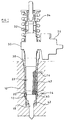
- the fuel injector illustrated in the accompanying drawings is intended to be received within a bore 10 provided in a cylinder head 12, the cylinder head 12 being provided with a fuel supply passage 14 through which fuel is supplied to the injector from a fuel reservoir at relatively low pressure, for example a pressure of approximately 5 bar, and a backleak passage 16 connected to an appropriate drain reservoir.
- the injector comprises a nozzle body 18 including a blind bore within which a valve needle is reciprocable, an end of the needle being engageable with a seating defined adjacent the blind end of the bore.
- the valve needle includes thrust surfaces which are orientated such that the application of fuel under pressure thereto applies a force to the valve needle urging the needle away from its seating to permit fuel to flow past the seating to one or more outlet openings provided in the nozzle body 18 downstream of the seating.
- the nozzle body 18 engages a distance piece 20 which in turn engages a spring housing 22.
- the spring housing 22 is provided with a bore defining a spring chamber 24 within which a compression spring 26 is located, an end of the compression spring 26 engaging a spring abutment member 28 which is carried by an end of the valve needle remote from the end arranged to engage the seating to bias the valve needle towards the seating.
- the upper end of the spring housing 22 engages a pump housing 30 including a bore within which a pumping plunger 32 is reciprocable under the influence of a cam arrangement, a return spring 34 being provided to withdraw the plunger 32 from its bore.
- a spill valve arrangement 36 communicates with the bore of the pump housing 30 to control the operation of the injection.
- the spill valve arrangement 36 takes the form of an electromagnetically actuated valve which is actuable under the control of an appropriate control arrangement.
- the bore of the pump housing 30 further communicates through a passage (not shown) with the blind bore of the nozzle body 18.
- a cap nut 38 engages the nozzle body 18 and secures the nozzle body 18, the distance piece 20 and the spring housing 22 to the pump housing 30.
- the cap nut 38 and bore 10 together define a chamber 40 with which the supply passage 14 communicates, O-ring seals 42 being provided between the cap nut 38 and wall of the bore 10 in order to substantially prevent leakage of fuel from the chamber 40.
- the cap nut 38 is shaped to include a region 38 a the inner surface of which engages the spring housing 22 to locate the spring housing 22 concentrically with the cap nut 38.
- the inner surface of the cap nut 38 is provided with first and second annular recesses defining first and second annular inlet chambers 44 which communicate through respective passages 46 with the chamber 40.
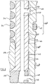
- the inner surface of the cap nut 38 is shaped to include regions 38 b of diameter slightly greater than the outer diameter of the spring housing 22 to define annular, cylindrical filtration flow paths which communicate with respective ones of the inlet chambers 44 and with respective delivery chambers 48 defined by annular recesses formed in the cap nut 38.
- the filtration flow paths may be defined, in part, by regions of the spring housing 22 of slightly reduced diameter, as shown in Figure 2.
- one of the delivery chambers 48 is defined, in part, by the outer surface of the distance piece 20.
- the delivery chambers 48 communicate through passages 50 with a supply passage 52 which extends within the distance piece 20 and the spring housing 22.
- the spill valve arrangement 36 controls communication between the supply passage 52 and the bore of the pump housing 30.
- the pumping plunger 32 In use, starting from the position in which the pumping plunger 32 occupies its innermost position, the pumping plunger 32 being about to commence outward movement under the action of the spring 34, and with the spill valve arrangement 36 being actuated to permit communication between the bore of the pump housing 30 and the supply passage 52, movement of the pumping plunger 32 allows fuel to flow into the bore of the pump housing 30, the fuel being supplied from the chamber 40 through the passages 46 to the inlet chambers 44, and from the inlet chambers 44 past the regions 38 b , through the delivery chambers 48 to the supply passage 52, and past the valve of the spill valve arrangement 36.
- the spill valve arrangement 36 When injection is required to commence, the spill valve arrangement 36 is closed thereby terminating the return flow of fuel, continued inward movement of the pumping plunger 32 pressurizing the fuel within the bore of the pump housing 30 and the passages and bores in communication therewith, thus increasing the fuel pressure applied to the thrust surfaces of the valve needle, and a point will be reached beyond which the valve needle is able to lift from its seating against the action of the spring 26. Fuel injection then takes place. In order to terminate fuel injection, the spill valve arrangement 36 is actuated to once more permit fuel to flow from the bore of the pump housing 30 to the supply passage 52 and to the fuel reservoir. Such communication permits the fuel pressure within the bore of the pump housing 30 and the fuel pressure applied to the needle to fall rapidly with the result that the valve needle is able to return into engagement with its seating under the action of the spring 26.
- the filtration flow paths are of generally annular form, it will be appreciated that this need not be the case, and that the filtration flow paths could be defined, for example, by a series of grooves provided in the outer surface of the spring housing 22 or the inner surface of the cap nut 38. It will further be appreciated that the filtration flow paths could be defined between other components of the fuel injection, and that the invention is applicable to other types of fuel injector than that described hereinbefore.
Landscapes
- Engineering & Computer Science (AREA)
- Chemical & Material Sciences (AREA)
- Combustion & Propulsion (AREA)
- Mechanical Engineering (AREA)
- General Engineering & Computer Science (AREA)
- Fuel-Injection Apparatus (AREA)
Applications Claiming Priority (2)
| Application Number | Priority Date | Filing Date | Title |
|---|---|---|---|
| GB9804110 | 1998-02-27 | ||
| GBGB9804110.6A GB9804110D0 (en) | 1998-02-27 | 1998-02-27 | Fuel injector |
Publications (2)
| Publication Number | Publication Date |
|---|---|
| EP0939219A2 true EP0939219A2 (de) | 1999-09-01 |
| EP0939219A3 EP0939219A3 (de) | 2000-08-23 |
Family
ID=10827653
Family Applications (1)
| Application Number | Title | Priority Date | Filing Date |
|---|---|---|---|
| EP98309996A Withdrawn EP0939219A3 (de) | 1998-02-27 | 1998-12-07 | Kraftstoffeinspritzventil |
Country Status (3)
| Country | Link |
|---|---|
| US (1) | US6192870B1 (de) |
| EP (1) | EP0939219A3 (de) |
| GB (1) | GB9804110D0 (de) |
Cited By (1)
| Publication number | Priority date | Publication date | Assignee | Title |
|---|---|---|---|---|
| GB2350645A (en) * | 1999-06-04 | 2000-12-06 | Delphi Tech Inc | Unit fuel injector with fuel filtration path |
Families Citing this family (3)
| Publication number | Priority date | Publication date | Assignee | Title |
|---|---|---|---|---|
| DE19941054A1 (de) * | 1999-08-28 | 2001-03-01 | Bosch Gmbh Robert | Kraftstoffeinspritzventil für Brennkraftmaschinen |
| GB0609519D0 (en) * | 2006-05-12 | 2006-06-21 | Delphi Tech Inc | Fuel injector |
| US8500045B2 (en) * | 2009-07-20 | 2013-08-06 | Caterpillar Inc. | Parallel circuit fuel filtration for fuel injectors |
Family Cites Families (14)
| Publication number | Priority date | Publication date | Assignee | Title |
|---|---|---|---|---|
| US2507355A (en) * | 1946-01-17 | 1950-05-09 | Sola Giuseppe | Filter for injectors for combustion engines |
| DE899295C (de) * | 1949-07-12 | 1953-12-10 | Muenchner Motorzubehoer G M B | Einspritzduese fuer Brennkraftmaschinen |
| US4146178A (en) * | 1977-05-18 | 1979-03-27 | Caterpillar Tractor Co. | Unit fuel injector |
| AT362201B (de) * | 1978-03-29 | 1981-04-27 | Friedmann & Maier Ag | Brennstoffeinspritzvorrichtung fuer einspritz- brennkraftmaschinen |
| AT397129B (de) * | 1984-01-20 | 1994-02-25 | Bosch Robert Ag | Kraftstoffeinspritzdüse |
| AT387824B (de) * | 1984-06-06 | 1989-03-28 | Steyr Daimler Puch Ag | Kraftstoff-einspritzduese fuer brennkraftmaschinen |
| DE4142940C2 (de) * | 1991-12-24 | 1994-01-27 | Bosch Gmbh Robert | Elektrisch gesteuerte Pumpedüse |
| DE4222628A1 (de) * | 1992-07-10 | 1994-01-13 | Bosch Gmbh Robert | Brennstoffeinspritzvorrichtung |
| US5320278A (en) * | 1993-07-26 | 1994-06-14 | Cummins Engine Company, Inc. | High pressure fuel injector with fuel drainage valve |
| US5345913A (en) * | 1993-11-24 | 1994-09-13 | Caterpillar Inc. | Injector assembly |
| US6161773A (en) * | 1994-05-31 | 2000-12-19 | Caterpillar Inc. | Fuel injector nozzle with guide to check clearance passage providing injection rate shaping |
| US6003497A (en) * | 1994-10-31 | 1999-12-21 | Caterpillar Inc. | Mechanically actuated hydraulically amplified fuel injector with electrically controlled pressure relief |
| US5636615A (en) * | 1995-02-21 | 1997-06-10 | Diesel Technology Company | Fuel pumping and injection systems |
| US6026786A (en) * | 1997-07-18 | 2000-02-22 | Caterpillar Inc. | Method and apparatus for controlling a fuel injector assembly of an internal combustion engine |
-
1998
- 1998-02-27 GB GBGB9804110.6A patent/GB9804110D0/en not_active Ceased
- 1998-12-07 EP EP98309996A patent/EP0939219A3/de not_active Withdrawn
-
1999
- 1999-01-19 US US09/232,789 patent/US6192870B1/en not_active Expired - Fee Related
Non-Patent Citations (1)
| Title |
|---|
| None |
Cited By (1)
| Publication number | Priority date | Publication date | Assignee | Title |
|---|---|---|---|---|
| GB2350645A (en) * | 1999-06-04 | 2000-12-06 | Delphi Tech Inc | Unit fuel injector with fuel filtration path |
Also Published As
| Publication number | Publication date |
|---|---|
| EP0939219A3 (de) | 2000-08-23 |
| GB9804110D0 (en) | 1998-04-22 |
| US6192870B1 (en) | 2001-02-27 |
Similar Documents
| Publication | Publication Date | Title |
|---|---|---|
| EP0878623B1 (de) | Kraftstoffeinspritzventil | |
| US5505384A (en) | Rate shaping control valve for fuel injection nozzle | |
| US5765755A (en) | Injection rate shaping nozzle assembly for a fuel injector | |
| EP0943797A1 (de) | Kraftstoffeinspritzventil | |
| EP0953107B1 (de) | Kraftstoffeinspritzpumpe mit hydraulisch gesteuertem überlaufventil | |
| US5560825A (en) | Edge filter for a high pressure hydraulic system | |
| US5832954A (en) | Check valve assembly for inhibiting Helmholtz resonance | |
| US6820594B2 (en) | Valve for controlling a communication in a high-pressure fluid system, in particular in a fuel injection system for an internal combustion engine | |
| US5626119A (en) | Fuel system | |
| US6109542A (en) | Servo-controlled fuel injector with leakage limiting device | |
| US6192870B1 (en) | Fuel injector | |
| US6811092B2 (en) | Fuel injector nozzle with pressurized needle valve assembly | |
| CN100473821C (zh) | 具有柱塞的燃油泵及使用这种燃油泵的燃油供应系统 | |
| US6976638B2 (en) | Fuel injection system for an internal combustion engine | |
| EP0965750B1 (de) | Brennstoffeinspritzventil | |
| US6006782A (en) | Snubber valve | |
| EP0630443B1 (de) | Brennkraftstoffpumpe | |
| EP0821154B1 (de) | Kraftstoffpumpenvorrichtung | |
| EP1065368A2 (de) | Kraftstoffeinspritzventil | |
| JP3884665B2 (ja) | 蓄圧式分配型燃料噴射ポンプ | |
| EP0805271B1 (de) | Brennstoffeinspritzsystem | |
| EP1236883A2 (de) | Kraftstoffsystem | |
| Lambeth | Fuel injector | |
| GB2349670A (en) | Unit fuel injector with a filtration path between the plunger and its bore | |
| EP1247976A2 (de) | Überdruckentlastungsventil in einem Kraftstoffsystem |
Legal Events
| Date | Code | Title | Description |
|---|---|---|---|
| PUAI | Public reference made under article 153(3) epc to a published international application that has entered the european phase |
Free format text: ORIGINAL CODE: 0009012 |
|
| AK | Designated contracting states |
Kind code of ref document: A2 Designated state(s): DE ES FR GB IT |
|
| AX | Request for extension of the european patent |
Free format text: AL;LT;LV;MK;RO;SI |
|
| RAP1 | Party data changed (applicant data changed or rights of an application transferred) |
Owner name: LUCAS INDUSTRIES LIMITED |
|
| PUAL | Search report despatched |
Free format text: ORIGINAL CODE: 0009013 |
|
| AK | Designated contracting states |
Kind code of ref document: A3 Designated state(s): AT BE CH CY DE DK ES FI FR GB GR IE IT LI LU MC NL PT SE |
|
| AX | Request for extension of the european patent |
Free format text: AL;LT;LV;MK;RO;SI |
|
| 17P | Request for examination filed |
Effective date: 20010119 |
|
| RAP1 | Party data changed (applicant data changed or rights of an application transferred) |
Owner name: DELPHI TECHNOLOGIES, INC. |
|
| AKX | Designation fees paid |
Free format text: DE ES FR GB IT |
|
| 17Q | First examination report despatched |
Effective date: 20021021 |
|
| STAA | Information on the status of an ep patent application or granted ep patent |
Free format text: STATUS: THE APPLICATION IS DEEMED TO BE WITHDRAWN |
|
| 18D | Application deemed to be withdrawn |
Effective date: 20030301 |