EP0939237A2 - Schnell verriegelnde Antirotationsvorrichtung für Fernsteuerung - Google Patents
Schnell verriegelnde Antirotationsvorrichtung für Fernsteuerung Download PDFInfo
- Publication number
- EP0939237A2 EP0939237A2 EP99200412A EP99200412A EP0939237A2 EP 0939237 A2 EP0939237 A2 EP 0939237A2 EP 99200412 A EP99200412 A EP 99200412A EP 99200412 A EP99200412 A EP 99200412A EP 0939237 A2 EP0939237 A2 EP 0939237A2
- Authority
- EP
- European Patent Office
- Prior art keywords
- box
- holding sleeve
- rotation
- opening
- shaped element
- Prior art date
- Legal status (The legal status is an assumption and is not a legal conclusion. Google has not performed a legal analysis and makes no representation as to the accuracy of the status listed.)
- Withdrawn
Links
- 238000006243 chemical reaction Methods 0.000 claims abstract description 8
- 230000037431 insertion Effects 0.000 claims description 7
- 238000003780 insertion Methods 0.000 claims description 7
- 241000826860 Trapezium Species 0.000 claims description 3
- 230000000295 complement effect Effects 0.000 claims description 3
- 230000010355 oscillation Effects 0.000 description 4
- 230000005540 biological transmission Effects 0.000 description 2
- 230000008878 coupling Effects 0.000 description 2
- 238000010168 coupling process Methods 0.000 description 2
- 238000005859 coupling reaction Methods 0.000 description 2
- 230000002452 interceptive effect Effects 0.000 description 1
- 238000003801 milling Methods 0.000 description 1
Images




Classifications
-
- F—MECHANICAL ENGINEERING; LIGHTING; HEATING; WEAPONS; BLASTING
- F16—ENGINEERING ELEMENTS AND UNITS; GENERAL MEASURES FOR PRODUCING AND MAINTAINING EFFECTIVE FUNCTIONING OF MACHINES OR INSTALLATIONS; THERMAL INSULATION IN GENERAL
- F16C—SHAFTS; FLEXIBLE SHAFTS; ELEMENTS OR CRANKSHAFT MECHANISMS; ROTARY BODIES OTHER THAN GEARING ELEMENTS; BEARINGS
- F16C1/00—Flexible shafts; Mechanical means for transmitting movement in a flexible sheathing
- F16C1/26—Construction of guiding-sheathings or guiding-tubes
- F16C1/262—End fittings; Attachment thereof to the sheathing or tube
Definitions
- the present invention refers to a fast locking anti-rotation device in a remote control apparatus.
- the box-shaped element or box element of the control lever has at least one opening for the passage of at least one cable and the positioning of the reaction sheath.
- Such insertion by rotation in the case where the remote control device is placed on machines subjected to vibrations, can rotate and return to the free deployment and release position so that the control is no longer firmly positioned. Moreover, it may also occur that an operator inadvertently operates on the holding sleeve, rotating it and bringing it into the box release position.
- a purpose of the present invention is to solve the problem of the firm positioning between the parts, notwithstanding any accidental actions or any vibration caused to the remote control device; this is in order to guarantee a constant correct positioning of the cable or of the cables in the control lever box or in the remote control box-shaped element.
- Another purpose of this invention is to facilitate the insertion of the cable reaction holding sleeve into the box or in the box-shaped element, whether it is inserted from the outside or from the inside of the box or of the box-shaped element, and whether there is the presence of one or more cables.
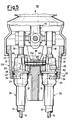
- a fast locking remote control device driven by means of single or multiple trailing cables with an anti-rotation device, is shown in accordance with the present invention.
- FIGS 1-4 illustrate a box-shaped element or box 11, for example in two joined pieces, which can be connected to a driving machine outer structure.
- the box 11 comprises a first opening 12 wherefrom the control lever 13 of a single cable core 14 extends, said cable can be moved inside a reaction sheath 15.
- the control lever 13 can oscillate around a pivot 16, which can be integral with the box 11, and has a hole 17 at one of its inner end suitable to receive the hook shaped curved end 18 of the cable core 14. It is possible to point out, in one half of the box 11, an enlargement 19 that is placed underneath the hook shaped curved end 18. In particular such an enlargement 19 has a centrally hollow initial portion 20, into which the curved end 18 is inserted before reaching the slanting ramp 21 towards a subsequent upper end 22 of the same enlargement 19.
- This enlargement 19 has, at least in part, a curved shape that follows the oscillations of the hole 17 of the control lever 13. In this way, the secure engagement of the curved end 18 in the hole 17, for small oscillations of the lever, is guaranteed.
- the fast locking/unlocking sleeve is centrally provided with a shaped through passing cavity (not shown) which allows the passage of cable 14 that maintains its continuity through folded seams of at least two portions, not shown in the figures, with the curved end 18.
- This holding sleeve 26, which also has a support function, can be inserted, in a removable way, in the opening 23, thanks to two couples of teeth 24 and 25, which radially project outwardly from the body of the holding sleeve 26.
- Each of the teeth 24 and 25 occupies a circular portion of the casing ( e.g. a little under a quarter of the perimeter) and the teeth are placed on opposite sides with respects to an annular crown 28.
- the opening 23 generally has two circular portions 27 with a diameter a little larger than that of the holding sleeve 26 and two enlarged or expanded areas 30 in the opening 23 into which the couples of teeth 24 and 25 can be inserted.
- an annular cavity 29 is provided to the opening 23 and said cavity receives and houses, at least partially, the thickness of the annular crown 28.
- the thickness of the box wall wherein the opening 23 is realised must be such that said wall can be inserted, when the sleeve 26 is rotated, between the teeth 24 or 25 and the annular crown 28 thus causing a firm locking of the sleeve through a coupling similar to that of a bayonet (figures 1-3).
- two flat surfaces 31 are obtained on the lateral surface of the holding sleeve 26, which in the example are two flat milled surfaces on opposite sides.
- This anti-rotation element 32 comprises a plate 33 with a central hole in an oval opening 34 with two flat portions 35. These flat portions 35 firmly abut, once the anti-rotation element is coupled to the box 11, against the flat surfaces 31.
- Such positioning can be realised either by snapping or by a side movement of the cover element 32 which is positioned on the box 11 thanks to a suitable eccentric eyelet of the opening 34.
- the flat portions 35 by abutting on the flat surfaces 31 of the holding sleeve 26, realise an engagement that prevents any rotation, even accidental, of the holding sleeve 26 which is inserted in the opening 23 of the box.
- Figures 5-7 show a second possible embodiment of the present invention wherein, when possible, equal reference numbers indicate equal or similar elements.
- the box is replaced by a box-shaped element 111 in which there are two cavities 41 divided into two portions by the flanges 42 provided with the openings 23 similar to those previously described.
- Figure 5 shows a fast locking device of a remote control obtained by means of two trailing cables 14 with corresponding sheaths 15, said cables are connected, by known means, to a lever 13, through a specific coupling. Equal elements are indicated with equal elements.
- the end of the holding sleeve 26 facing the control lever 13 is provided with two appendixes 40 which are placed at opposite sides along the same generating line of the two couples of teeth 24 and 25 and which project outwardly.
- each of the two holding sleeves 26 has at least one flat surface 31, which is realised for example through a flat milling operation at least on its lateral surface facing the control lever.
- an anti-rotation element 132 has been realised, which can be coupled to the two holding sleeves 26, in the form of an additional element which can be inserted into the box-shaped element 111, always on the side towards the control lever.
- This additional anti-rotation element 132 is formed by a U-shaped element comprising a central body 80, which has a isosceles trapezium shaped section, and which is provided with a threaded hole 81 suitable to receive a positioning threaded element, which is not shown.
- Two legs 82 extend from said central body 80 on the slanting lateral sides of the trapezium section so as to continue an outer surface of the two slanting sides of the central body 80.
- two slanting surfaces 83 are realised that abut against the flat surfaces 31 of the two holding sleeves 26 thus locking said sleeves into position and preventing the backward rotation and the slipping from the openings 23 of the box-shaped element 111.
- the central body 80 is fitted into a hollow seat 84 obtained in the box-shaped element 111. Moreover, on one of its base surfaces, e.g. the one with larger dimensions, the central body 80 has two small projections 85 that protrude and cause its forced insertion into the hollow seat 84 with a final firm positioning as a result.
- Figure 7 shows more clearly how this additional anti-rotation element 132 is realised with a central body 80, provided with projections 85 and with lateral legs 82, and with slanting lateral flat surfaces 83 for the engagement with the flat surfaces 31 of the holding sleeves 26.
- Figures 8-10 show a further third embodiment of the present invention.
- an anti-rotation element 232 is provided for each of the two holding sleeves 26, in the form of an additional element which can be put together with each of the two sleeves inside a box-shaped element 111, similar to the preceding one.
- Every anti-rotation element 232 has a C-shaped upper area 90 that works as a ring and is suitable to fit on a hollow cylindrical extension 60 of the holding sleeve 26, that projects opposite to the areas provided with the appendixes 40.
- a leg 91 extends from said upper area 90 and has a flat surface 92 on one side and a rounded surface 93 on the other side.
- the rounded side 93 of the leg 91 is suitable to fit into a complementary cavity 94, provided with a side ledge 96, obtained in a central portion 95 of the box-shaped element 111.
- One of the two sides 97 of the anti-rotation element 232 engages with the side ledge 96 of the cavity 94. Moreover, the flat surface 92 engages with the flat surface 31 obtained on the holding sleeve 26.
- the present invention allows, in a bayonet locking system applied to a remote control apparatus through trailing cables (in particular push-pull cables), a secure and firm locking into seat.
Landscapes
- Engineering & Computer Science (AREA)
- General Engineering & Computer Science (AREA)
- Health & Medical Sciences (AREA)
- Oral & Maxillofacial Surgery (AREA)
- Mechanical Engineering (AREA)
- Flexible Shafts (AREA)
- Mechanical Control Devices (AREA)
- Details Of Television Systems (AREA)
- Selective Calling Equipment (AREA)
Applications Claiming Priority (2)
| Application Number | Priority Date | Filing Date | Title |
|---|---|---|---|
| ITMI980369 | 1998-02-25 | ||
| ITMI980369 IT1302563B1 (it) | 1998-02-25 | 1998-02-25 | Dispositivo antirotazione in un comando a distanza ad aggancio rapido |
Publications (2)
| Publication Number | Publication Date |
|---|---|
| EP0939237A2 true EP0939237A2 (de) | 1999-09-01 |
| EP0939237A3 EP0939237A3 (de) | 2000-08-30 |
Family
ID=11379073
Family Applications (1)
| Application Number | Title | Priority Date | Filing Date |
|---|---|---|---|
| EP99200412A Withdrawn EP0939237A3 (de) | 1998-02-25 | 1999-02-12 | Schnell verriegelnde Antirotationsvorrichtung für Fernsteuerung |
Country Status (2)
| Country | Link |
|---|---|
| EP (1) | EP0939237A3 (de) |
| IT (1) | IT1302563B1 (de) |
Cited By (3)
| Publication number | Priority date | Publication date | Assignee | Title |
|---|---|---|---|---|
| EP1114937A1 (de) * | 1999-12-29 | 2001-07-11 | SILA HOLDING INDUSTRIALE S.r.l. | Vorrichtung zur Befestigung eines langgestreckten Körpers, insbesondere einer Bowdenzughülle, an einem Träger |
| WO2020263156A1 (en) * | 2019-06-26 | 2020-12-30 | Ålö AB | A control system using a control cable, an adapter element for such a system, and a control cable having such an adapter element |
| US11828326B2 (en) | 2019-06-26 | 2023-11-28 | Ålö AB | Control system using a control cable, an adapter element for such a system, and a control cable having such an adapter element |
Citations (1)
| Publication number | Priority date | Publication date | Assignee | Title |
|---|---|---|---|---|
| EP0285299A2 (de) | 1987-04-03 | 1988-10-05 | Morse Controls Limited | Fernbedienung |
Family Cites Families (2)
| Publication number | Priority date | Publication date | Assignee | Title |
|---|---|---|---|---|
| FR2147673A5 (de) * | 1971-07-29 | 1973-03-09 | Kienzle Apparate Gmbh | |
| IT1292041B1 (it) * | 1997-05-30 | 1999-01-25 | Brambilla Cornelia | Disposizione di aggancio rapipo di un comando a distanza mediante cavi flessibili singoli o plurimi |
-
1998
- 1998-02-25 IT ITMI980369 patent/IT1302563B1/it active IP Right Grant
-
1999
- 1999-02-12 EP EP99200412A patent/EP0939237A3/de not_active Withdrawn
Patent Citations (1)
| Publication number | Priority date | Publication date | Assignee | Title |
|---|---|---|---|---|
| EP0285299A2 (de) | 1987-04-03 | 1988-10-05 | Morse Controls Limited | Fernbedienung |
Cited By (3)
| Publication number | Priority date | Publication date | Assignee | Title |
|---|---|---|---|---|
| EP1114937A1 (de) * | 1999-12-29 | 2001-07-11 | SILA HOLDING INDUSTRIALE S.r.l. | Vorrichtung zur Befestigung eines langgestreckten Körpers, insbesondere einer Bowdenzughülle, an einem Träger |
| WO2020263156A1 (en) * | 2019-06-26 | 2020-12-30 | Ålö AB | A control system using a control cable, an adapter element for such a system, and a control cable having such an adapter element |
| US11828326B2 (en) | 2019-06-26 | 2023-11-28 | Ålö AB | Control system using a control cable, an adapter element for such a system, and a control cable having such an adapter element |
Also Published As
| Publication number | Publication date |
|---|---|
| EP0939237A3 (de) | 2000-08-30 |
| ITMI980369A1 (it) | 1999-08-25 |
| IT1302563B1 (it) | 2000-09-29 |
Similar Documents
| Publication | Publication Date | Title |
|---|---|---|
| JP5208942B2 (ja) | 車両シート、特に自動車用シートのアクチュエーター | |
| EP0110027B1 (de) | Baugerüstverbindung | |
| JP4140665B2 (ja) | パイプクランプ | |
| JP3056721B2 (ja) | 連結具 | |
| US5039133A (en) | Suction nozzle coupling having rotatably mounted therein a connector for a suction hose | |
| RU2163220C2 (ru) | Надцентровое запирающее устройство | |
| JP3111082U (ja) | 連結要素 | |
| JP2000166630A (ja) | 傘のろくろ | |
| KR100191831B1 (ko) | 전기 코넥터의 제1 및 제2 절반부를 착탈 가능하게 결합하는 장치 | |
| BR9809538A (pt) | Conexão de tubulação e combinação de uma conexão de tubulação e uma ferramenta para desencaixe. | |
| EP0939237A2 (de) | Schnell verriegelnde Antirotationsvorrichtung für Fernsteuerung | |
| FR2843492A1 (fr) | Connecteur muni d'un moyen de verrouillage lateral | |
| US6733201B2 (en) | Plug connection with installation securing device | |
| US6024509A (en) | Arrangement for remote-control fast hooking by means of flexible single or multiple cables | |
| FR2548744A1 (fr) | Organe de logement pour agrafe | |
| KR100534925B1 (ko) | 조립체 고정장치 | |
| FR2659480A1 (fr) | Assemblage combustible de reacteur nucleaire. | |
| JPS6031272Y2 (ja) | キヤビネツト | |
| FR2569899A1 (fr) | Boitier modulaire pour appareillage electrique et modules correspondants | |
| US6397440B1 (en) | Assembly of a buckle mechanism and a blade and a method of securing and releasing the blade to the buckle mechanism | |
| GB2298176A (en) | Connection and securing devices for toggle joints of scraper-chain conveyors and the like. | |
| JP3308500B2 (ja) | マンホール用蓋のロック構造 | |
| JP2009142126A (ja) | プロテクタの固定構造 | |
| JP3221551B2 (ja) | 電気機器取付装置 | |
| JP3845911B2 (ja) | 照明器具 |
Legal Events
| Date | Code | Title | Description |
|---|---|---|---|
| PUAI | Public reference made under article 153(3) epc to a published international application that has entered the european phase |
Free format text: ORIGINAL CODE: 0009012 |
|
| AK | Designated contracting states |
Kind code of ref document: A2 Designated state(s): DE ES FR GB IT |
|
| AX | Request for extension of the european patent |
Free format text: AL;LT;LV;MK;RO;SI |
|
| PUAL | Search report despatched |
Free format text: ORIGINAL CODE: 0009013 |
|
| AK | Designated contracting states |
Kind code of ref document: A3 Designated state(s): AT BE CH CY DE DK ES FI FR GB GR IE IT LI LU MC NL PT SE |
|
| AX | Request for extension of the european patent |
Free format text: AL;LT;LV;MK;RO;SI |
|
| 17P | Request for examination filed |
Effective date: 20010103 |
|
| AKX | Designation fees paid |
Free format text: DE ES FR GB IT |
|
| GRAH | Despatch of communication of intention to grant a patent |
Free format text: ORIGINAL CODE: EPIDOS IGRA |
|
| STAA | Information on the status of an ep patent application or granted ep patent |
Free format text: STATUS: THE APPLICATION IS DEEMED TO BE WITHDRAWN |
|
| 18D | Application deemed to be withdrawn |
Effective date: 20030920 |