EP0939248A2 - Dispositif d'engrenage avec denture extérieure - Google Patents
Dispositif d'engrenage avec denture extérieure Download PDFInfo
- Publication number
- EP0939248A2 EP0939248A2 EP99103816A EP99103816A EP0939248A2 EP 0939248 A2 EP0939248 A2 EP 0939248A2 EP 99103816 A EP99103816 A EP 99103816A EP 99103816 A EP99103816 A EP 99103816A EP 0939248 A2 EP0939248 A2 EP 0939248A2
- Authority
- EP
- European Patent Office
- Prior art keywords
- gear unit
- toothing
- unit according
- carrier
- jacket
- Prior art date
- Legal status (The legal status is an assumption and is not a legal conclusion. Google has not performed a legal analysis and makes no representation as to the accuracy of the status listed.)
- Granted
Links
Images






Classifications
-
- F—MECHANICAL ENGINEERING; LIGHTING; HEATING; WEAPONS; BLASTING
- F16—ENGINEERING ELEMENTS AND UNITS; GENERAL MEASURES FOR PRODUCING AND MAINTAINING EFFECTIVE FUNCTIONING OF MACHINES OR INSTALLATIONS; THERMAL INSULATION IN GENERAL
- F16H—GEARING
- F16H57/00—General details of gearing
- F16H57/02—Gearboxes; Mounting gearing therein
- F16H57/02004—Gearboxes; Mounting gearing therein the gears being positioned relative to one another by rolling members or by specially adapted surfaces on the gears, e.g. by a rolling surface with the diameter of the pitch circle
-
- F—MECHANICAL ENGINEERING; LIGHTING; HEATING; WEAPONS; BLASTING
- F16—ENGINEERING ELEMENTS AND UNITS; GENERAL MEASURES FOR PRODUCING AND MAINTAINING EFFECTIVE FUNCTIONING OF MACHINES OR INSTALLATIONS; THERMAL INSULATION IN GENERAL
- F16H—GEARING
- F16H1/00—Toothed gearings for conveying rotary motion
- F16H1/02—Toothed gearings for conveying rotary motion without gears having orbital motion
- F16H1/04—Toothed gearings for conveying rotary motion without gears having orbital motion involving only two intermeshing members
- F16H1/06—Toothed gearings for conveying rotary motion without gears having orbital motion involving only two intermeshing members with parallel axes
- F16H1/08—Toothed gearings for conveying rotary motion without gears having orbital motion involving only two intermeshing members with parallel axes the members having helical, herringbone, or like teeth
-
- F—MECHANICAL ENGINEERING; LIGHTING; HEATING; WEAPONS; BLASTING
- F16—ENGINEERING ELEMENTS AND UNITS; GENERAL MEASURES FOR PRODUCING AND MAINTAINING EFFECTIVE FUNCTIONING OF MACHINES OR INSTALLATIONS; THERMAL INSULATION IN GENERAL
- F16H—GEARING
- F16H55/00—Elements with teeth or friction surfaces for conveying motion; Worms, pulleys or sheaves for gearing mechanisms
- F16H55/02—Toothed members; Worms
- F16H55/17—Toothed wheels
-
- Y—GENERAL TAGGING OF NEW TECHNOLOGICAL DEVELOPMENTS; GENERAL TAGGING OF CROSS-SECTIONAL TECHNOLOGIES SPANNING OVER SEVERAL SECTIONS OF THE IPC; TECHNICAL SUBJECTS COVERED BY FORMER USPC CROSS-REFERENCE ART COLLECTIONS [XRACs] AND DIGESTS
- Y10—TECHNICAL SUBJECTS COVERED BY FORMER USPC
- Y10T—TECHNICAL SUBJECTS COVERED BY FORMER US CLASSIFICATION
- Y10T74/00—Machine element or mechanism
- Y10T74/19—Gearing
- Y10T74/19642—Directly cooperating gears
- Y10T74/19647—Parallel axes or shafts
-
- Y—GENERAL TAGGING OF NEW TECHNOLOGICAL DEVELOPMENTS; GENERAL TAGGING OF CROSS-SECTIONAL TECHNOLOGIES SPANNING OVER SEVERAL SECTIONS OF THE IPC; TECHNICAL SUBJECTS COVERED BY FORMER USPC CROSS-REFERENCE ART COLLECTIONS [XRACs] AND DIGESTS
- Y10—TECHNICAL SUBJECTS COVERED BY FORMER USPC
- Y10T—TECHNICAL SUBJECTS COVERED BY FORMER US CLASSIFICATION
- Y10T74/00—Machine element or mechanism
- Y10T74/19—Gearing
- Y10T74/19851—Gear and rotary bodies
-
- Y—GENERAL TAGGING OF NEW TECHNOLOGICAL DEVELOPMENTS; GENERAL TAGGING OF CROSS-SECTIONAL TECHNOLOGIES SPANNING OVER SEVERAL SECTIONS OF THE IPC; TECHNICAL SUBJECTS COVERED BY FORMER USPC CROSS-REFERENCE ART COLLECTIONS [XRACs] AND DIGESTS
- Y10—TECHNICAL SUBJECTS COVERED BY FORMER USPC
- Y10T—TECHNICAL SUBJECTS COVERED BY FORMER US CLASSIFICATION
- Y10T74/00—Machine element or mechanism
- Y10T74/19—Gearing
- Y10T74/1987—Rotary bodies
Definitions
- the invention relates to an externally toothed gear unit, in particular for heavy machine gearboxes and / or high-speed gearboxes, such as Turbomachinery gear, comprising a toothing carrier with a external teeth attached to a peripheral surface and one with connected to the gear carrier bearing journal or connecting part at least one axial end region of the toothing carrier.
- Gear units of the type considered here are used, for example for helical gear units, as described in the BHS brochure "BHS helical gear units, single-stage, for high-speed systems "with the printing note H-3 / 1-87 are shown.
- the large spur gears in particular take such gears Dimensions from, for example, 500 mm diameter to 1250 mm Diameter.
- the axial width of the large gears in the order of 200 - 600 mm with straight and single helical teeth are in the order of magnitude with double helical teeth from 250 - 700 mm.
- Full wave design means that a disc body with one piece a shaft is made, the shaft over the end faces of the Disk body protrudes and is used for storage.
- This full wave design has advantages. The tensions from centrifugal force and heat difference between the gear area and the central area are small. Also due to the solid construction, there are slight changes in shape (constant volume) for example when subjected to centrifugal force.
- the full wave design also has disadvantages. To explain this Disadvantages must first briefly on the type of manufacture of such gear units full wave design. It will be a first Steel casting, which the shaft and the disc body in one-piece construction includes. This steel casting is then forged then subjected to machining in order to to determine the final dimensions and especially the gearing to attach. For reducing the casting and forging tensions and in order to optimize the material structure, various Heat treatments carried out. Then at approx. Carburized 900 ° C and then hardened (case hardening).
- Gear units have also been considered where the disc body is shrunk onto the shaft. This type is only limited use because of high centrifugal and thermal loads a loosening of the disc body from the composite with the shaft body cannot be avoided with certainty. Therefore, it still exists the tendency towards one-piece construction.
- the invention has for its object a gear unit of the generic type In such a way that tension states that are difficult to control, especially hardness stress conditions avoided or be minimized.
- the invention proposes that the gear carrier either with a gear carrier jacket is executed, whose inner diameter is larger than the diameter of the bearing pin or connecting part and / or with a plurality of in axial direction successive and interconnected Gear carrier discs is executed.
- the voltage problem is reduced to the problem of one thin-walled tube, with a gear diameter of 900 mm and more thought of a wall thickness of 150 - 200 mm can be.
- the Wall thickness according to the ratio of the tooth diameter.
- This thin-walled tube is shorter than the wavelength in the case of a full-wave design. Thanks to the thin walls, it is almost uniform Heat treatment of all volume areas during case hardening too expect. Forging is also easier and with regard to on the avoidance of stress conditions in so far as the Gear carrier jacket can be rolled in a ring rolling mill.
- the gearing carrier jacket at at least one end, preferably at both ends, be connected to an end plate, in the Central area of the bearing journal or connecting part is arranged.
- end plates with a bearing journal or other Attachment attached are on both ends, so result in terms of storage for the gear unit the same options as in the known Solid shaft constructions or hollow shaft constructions.
- the end disks with trunnions or other connecting parts are in proportion relatively small-volume to the size of the entire gear unit, so that the problems with casting, forging and hardening and in operation can be avoided by centrifugal and temperature tensions.
- the end plate can be integral with the journal according to claim 3 or other connection part are manufactured. Because of the geometry result from a component consisting of end plate and bearing journal easier conditions for casting, forging and hardening.
- end disks that are closed in the center or up to to a small diameter corresponding to the journal diameter run radially inward, naturally less against centrifugal forces sensitive, i.e. they are less subject to a radial increase in diameter under the influence of centrifugal force. This could create tension in the Connection zone between the end plate and the gear carrier jacket to lead.
- One way to remedy this is by: one for an elastic behavior of the end plate under centrifugal force worries. Such elastic behavior can be prevented by the measures of claim 4 can be achieved.
- Another way to keep centrifugal stresses low in the connection area between the end plate and the gear carrier jacket according to claim 7 is that the end plate with one radially projecting beyond the connection point to the toothing carrier jacket Compensation mass is executed. Through the leveling compound is achieved that the end plate despite its compared to the Gearing carrier jacket further extending radially inward Material at the junction a similar or the same extent suffered under centrifugal force like the gearing carrier jacket.
- connection which may can also be used for centering according to claim 10 also possible in such a way that the end plate the connection point with the gearing carrier jacket axially clamped is, for the axial bracing of the end plate with the toothing support jacket axial clamping devices in the radial area of the connection point can be provided (claim 11) or radially within the connection point (claim 12), in particular in the axis area of the Gear unit (claim 13).
- Bearing journals can generally be used with case-hardened steel become. But it is also possible to use tempered steel for the end plates apply, because the requirements for the tooth engagement behavior of the Sprocket, the use of for the gearing carrier shell case hardened steel, exist on the end plates and on the bearing journal usually not.
- toothed carrier jacket proposed to be made from highly tempered tempered or nitrided steel.
- this design results in a more precise tension.
- the BHS publication H-3 / 1-87 makes the difference between the basic idea of the present invention also insofar clearly recognize as a hollow shaft type on page 11 of the publication is shown, wherein the bearing pin integral with the disc body are made so that despite the drilling the problems of Casting, forging and hardening persist, but in addition the Operating voltages due to centrifugal and thermal stresses, especially in the Bore area are significantly higher.
- the proposed invention is independent of the design of the external toothing applicable, for example, the toothing as a straight toothing, as helical teeth and as double helical teeth be designed according to claim 16.
- the thin-walled design of the gear unit according to the invention allows according to claim 17 that in the gear carrier near the External teeth with coolant and / or coolant Cooling surfaces are provided.
- This is significant because in particular high-speed gear units generate a lot of heat in the Intervention area occurs with a counter toothing that leads to thermal gradients can lead within the gear unit. The heat succeeds dissipate, the gradient course becomes flatter. This means less resulting thermal stresses and above all an essential more stable behavior of the toothed contact pattern.
- the coolant or / and coolant-carrying cooling surfaces comprise a cooling jacket, which is arranged radially within the tooth carrier shell. It can different coolant flow patterns to match the profile of the heat generation be generated.
- the coolant-carrying cooling surfaces essentially a coolant flow cause parallel to the axis direction of the gear unit; it is further according to claim 20 that the coolant-carrying cooling surfaces a coolant flow with a helical course around the axis effect the gear unit; it is further possible according to claim 21 that the coolant-carrying cooling surfaces cause a coolant flow, which at least once continuously over the axial length of the External toothing runs.
- the toothing carrier jacket of at least one one-piece pipe section is formed (claim 28).
- the invention strives Effect to a great extent when according to claim 29 with pipe section outer diameters (Gear diameter) of 900 mm and more the radial thickness of the pipe section is less than 200 mm, preferably less than 150 mm, with tube section outside diameters (Tooth diameter) of less than 900 mm the radial Thickness in the ratio of the pipe section outer diameter to 900 mm can decrease.
- the radial thickness of the pipe section is smaller than 30% of the pipe section outer diameter (tooth diameter), preferably less than 20%.
- the geometric relationships can also be done in this regard represent that according to claim 31, the radial thickness of the pipe section minus the tooth height greater than four times the normal module the teeth, preferably larger than eight times the normal module the gearing, is.
- the wall thickness regulations given above for the gear carrier jacket are also on it turned off that the connections with end plates without the occurrence additional dangerous voltages can be produced.
- Two or more toothed carrier disks can be stacked on top of one another follow (claim 32), wherein the axial thickness of the toothed carrier disks is less than 200 mm, preferably less than 150 mm.
- Particularly favorable access options for heat treatments and other treatments for the total volume of the gear carrier arise if, according to claim 33, the toothing carrier jacket of successive and indirect in the axial direction or gearing carrier washers directly connected to each other is formed.
- the subdivision into axially adjacent disks is particularly useful then when the external toothing for dental technology reasons is divided one or more times even in the axial direction, as e.g. is the case with serrations. Then one becomes the subdivision of the Discs with the axial subdivision of the external tooth length collapse.
- the second alternative of the invention can also be realized in such a way that the gear unit according to claim 36 a shaft with a radial flange includes and that on both sides of the radial flange each a toothing ring washer is appropriate. Even with such a construction there are relatively even and short distances for the Effect of treatment on the total volume of the gear unit forming parts. It is possible that according to claim 37 Gear carrier washers with the radial flange by one each torque transmitting and / or centering positive connection and axial tensioning means are connected.
- the dimensions according to are preferred Claim 38 adhered to the fact that the radial thickness of the toothing ring washers and the axial thickness of the tooth carrier ring washers is less than 300 mm, preferably less than 200 mm.
- the design of the gear unit according to the invention allows it according to Claim 41 that near the teeth, especially on the inner peripheral surface of the gear carrier jacket, temperature sensor elements, in particular thermocouples are attachable. This is not just an advantage because it shows dangerous conditions can. Rather, it is also possible, for example if it is present a fluid cooling, the coolant throughput depending to regulate from the measured temperatures.
- the inventive design according to both alternatives of the claim 1 can be according to claim 42 without further ado expand that the gear unit at least one pressure comb and / or has a pressure comb engagement ring, in particular as part of a End plate or a leveling mass attached to an end plate.
- a gear housing 10 is, a large spur gear 12 mounted by means of journal 14.
- This large spur gear 12 meshes with a small spur gear 16, which means Bearing pin 18 is also mounted in the gear housing.
- both spur gears 12 and 16 as so-called double helical teeth Spur gears are designed to axially fix each other to reach.
- the large spur gear 12 shows accordingly two spur gears 20a and 20b.
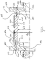
- the spur gear unit 12 shown in FIG. 2 corresponds to that, for example large spur gear 12 of FIG. 1.
- This spur gear unit 12 consists of a Gear carrier jacket 22 on which the two helical gears 20a and 20b according to FIG. 1 are attached.
- the ends 24a and 24b of the Toothed carrier jacket 22 are each with an end plate 26a and 26b connected. They are opposite centering lugs 28a and 28b End plates centered and in the axial direction by bolts 30a or 30b clamped.
- There are journals on the end disks 26a and 26b 32a and 32b are formed, which are mounted in bearings 34a and 34b.
- the gear carrier jacket 22 is described in the opening paragraph
- the end disks 26a, 26b go over rounded transition curves 36a, 36b into the journals 32a, 32b, whereby a radial elasticity of the end plates 26a, 26b is reached, so that the End disks 26a, 26b of any increases in diameter caused by centrifugal force of the gear carrier jacket 22 by elastic deformation can follow the transition curvatures 36a, 36b and thus Radial stresses at the connection points 38a, 38b kept low can be.
- end disks 26a, 26b are integral with Annular processes 40a, 40b are provided, which are dimensioned so that they at Rotation for equality or approximate equality of centrifugal Radial magnification on the end disks 26a, 26b on the one hand and on the gear rack 22 on the other hand.
- the inner diameter d1 of the toothing carrier jacket 22 is much larger than the diameter d2 of the bearing journal 32a, 32b.
- This difference in diameter between d1 and d2 is essential jointly responsible for the thin walls w1, w2, w3 in all Areas of the gear unit 12. It can be seen by comparing FIG. 2 with page 11, upper picture of the document that has already been cited several times BHS-H-3 / 1-87 a significant difference, which is that 2, the inner diameter d1 is significantly larger than that Diameter d2. This difference is even for the deployment small wall thicknesses w1-w3. That according to the upper Fig.
- the wall thickness w1 according to FIG. 2 is for a pipe section outer diameter d3 of 900 mm, for example 150-200 mm.
- the Wall thicknesses w2 and w3 result from scale comparison.
- analog parts are the same Reference numerals as in Fig. 1, each increased by the number 100, provided.
- the gear unit 212 is made of two toothed carrier disks 248a and 248b formed with the mediation of Hirth serrations 250 are centered against each other.
- the radial ring thickness dimensions w4 and the axial thickness dimensions a1 can be kept small, for example in the order of 350 mm, so that again each Volume element of the individual components relatively close to each nearest surface and thus heat and other Treatments are easily accessible.
- the embodiment according to FIG. 5 represents a combination of the embodiments 3 and FIG. 4.
- the big one succeeds Material block, namely the gearing carrier jacket 322, assembled from the washers 348a and 348b, to the smallest volume to reduce, so that particularly favorable conditions with regard to external Treatment accessibility for each volume element within the Annular washers 348a, 348b exist.
- Analog parts and shapes to the Embodiments according to FIGS. 3 and 4 are given the same reference numerals provided as there, however with the prefix 3.
- FIG. 6 shows a further alternative to FIG. 2.
- Analog parts are with the same reference numerals as there under the heading number 4.
- the jacket is 422 with the one end plate 426a integrally formed, while the other end plate 426b, as in FIG. 2, on the toothing carrier jacket 422 is attached.
- the combined wheel body 422, 426a, 432a can be manufactured as described in the introduction to the description.
- toothed carrier disks 648a and 648b connected by tie bolts 654 and Hirth serrations 650 and at the joints 638a and 638b with the trunnions 632a and 632b connected in any way, e.g. welded.
- the annular shape of the toothed carrier discs 648a and 648b serves to introduce a torsion shaft 656, for example by a toothing 658 with a connecting part 660 is connected torque-wise, which on the journal 632b flanged at 662.
- the toothing 658 can also by a Screw connection or a different type of coupling, for example a Membrane coupling to be replaced.
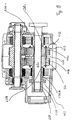
- a cooling jacket is located within the toothing carrier jacket 722 764 arranged, which serves to guide a coolant.
- the Coolant comes from a first port 766a on the journal 732a and flows to a second junction 766b on the Bearing journal 732b.
- FIG. 9 The flow conditions according to FIG. 9 are detailed in FIG. 9a shown.
- Fig. 9b the flow conditions are changed in that the Coolant in the direction of arrows 868a and 868b from both ends of the Gear carrier jacket 822 flows in and in the radial middle Area of the toothing carrier jacket through a radial bore 870 flows out, which is in the region of a recess 772 according to FIG. 9.
- a lubricant as a coolant use that serves at the same time, the gears 720a, 720b lubricate.
- Fig. 9c the coolant flow is changed in that the coolant in Direction of arrows 968a and 968b of Fig. 9 corresponding connection points 766a, 766b and through a bore 974 of the cooling jacket 964 through the central space 976 and through one of the pins 732a, 732b 9 can be derived.
- the coolant flows into the intermediate space in the direction of arrow 1078 between cooling jacket 1064 and gear carrier jacket 1022 and flows in the direction of arrows 1068a and 1068b, again for example via connection points 766a, 766b, as in FIG. 9 shown.
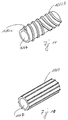
- cooling jacket 764th 9 corresponds to guide ribs 1180 attached in the axial Direction and a directional flow with high flow speed favor, approximately according to Fig. 9a.
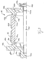
- FIG. 12 corresponds essentially to that Embodiment according to Fig. 6.
- a pressure comb 1384 attached with an annular Pressure comb receiving groove 1386 of a counter spur gear 1316 in intervention to secure the axial position.
- a shaft 1488 is provided with a radial flange 1490, on the one using Hirth gears 1452a and 1452b toothing carrier washers 1448a and 1448b using tie rods 1492 are attached.
- a shaft 1488 is provided with a radial flange 1490, on the one using Hirth gears 1452a and 1452b toothing carrier washers 1448a and 1448b using tie rods 1492 are attached.
- Fig. 14 shows a further embodiment, which is essentially the 12 corresponds to the embodiment.
- the annular pressure chamber receiving groove 1386 from FIG. 12 are on both sides of the Teeth 1520 both on the gear unit 1512 and on Counter spur gear 1516 pressure combs interacting in pairs 1584a, 1586a and 1584b, 1586b.
- Such Design brings in addition to an axial position-securing intervention advantageously a uniform transmission of axial force over both Pressure comb pairs 1584a, 1586a and 1584b, 1586b with themselves.
- cooling jacket of course, other forms of coolant can be used Areas are provided. So it would be in the case of the embodiment 9, the cooling jacket 764 is readily possible to be dropped entirely, which, however, becomes a major permanent Oil volume inside the gear unit would lead and possibly could lead to imbalance. In the case of the disc embodiment 5 it would also be conceivable for the two annular toothed carrier disks 348a and 348b with axially adjoining To provide channel bores.
- the coolant flow is, as has been emphasized several times, the respective one Temperature profile adjusted.
- Reduction gears with serration Double helical teeth
- the temperature development depends on whether the arrow is tapered in the direction of rotation or against the direction of rotation is rejuvenated. If the arrow tapers against the direction of rotation, the result is the highest tooth temperature in the middle of the arrow, so that you can see the oil here will feed according to Fig. 9d.
- Possible different tooth stiffness across the tooth width can by gear correction and / or by appropriate design and / or by varying the radial Thickness of the toothing carrier jacket can be compensated.
- FIG. 9 in conjunction with FIG. 9b is still The following should be noted:
- the coolant escaping in the direction of arrow 877 reaches in the area of the ring groove 772 together with additionally injected Gear lubricating oil in the gear 720a and 720b and flows through this towards the ring extensions 740a and 740b, provided that The direction of the arrow points in the direction of rotation. That on the ring extensions 740a Impinging lubricating oil is absorbed relatively gently and redirected.
- the collision to be expected in the absence of the ring extensions 740a of the oil with the gearbox walls, resulting in a strong spray would not occur. This would also relapse suppressed scattered oil in the direction of the toothings 720a and 720b, which could lead to a loss of performance.
- Axial drainage of the oil is desirable to avoid swirl and pressure losses to avoid.
- thermocouple 794 which shows the temperature can measure in the coolant flow.
- This thermocouple could also be in a radial bore 796 to keep the temperature as close as possible To measure toothing 720b.
- the thermocouple 794 corresponding signals can, for example, through the hollow Shaft journal 732 and corresponding transmission devices too a processing and display unit.
- the gear teeth are usually on the gear carrier jacket generated by machining.
- the gear units according to the invention come for example in Geared with a power transmission from 50,000 - 100,000 kW to Commitment.
Landscapes
- Engineering & Computer Science (AREA)
- General Engineering & Computer Science (AREA)
- Mechanical Engineering (AREA)
- Gears, Cams (AREA)
- Gear Transmission (AREA)
Applications Claiming Priority (2)
| Application Number | Priority Date | Filing Date | Title |
|---|---|---|---|
| DE19808519A DE19808519A1 (de) | 1998-02-27 | 1998-02-27 | Außenverzahnte Zahnradeinheit |
| DE19808519 | 1998-02-27 |
Publications (3)
| Publication Number | Publication Date |
|---|---|
| EP0939248A2 true EP0939248A2 (fr) | 1999-09-01 |
| EP0939248A3 EP0939248A3 (fr) | 2000-11-29 |
| EP0939248B1 EP0939248B1 (fr) | 2003-12-10 |
Family
ID=7859235
Family Applications (1)
| Application Number | Title | Priority Date | Filing Date |
|---|---|---|---|
| EP99103816A Expired - Lifetime EP0939248B1 (fr) | 1998-02-27 | 1999-02-26 | Dispositif d'engrenage avec denture extérieure |
Country Status (3)
| Country | Link |
|---|---|
| US (1) | US6334369B1 (fr) |
| EP (1) | EP0939248B1 (fr) |
| DE (2) | DE19808519A1 (fr) |
Cited By (2)
| Publication number | Priority date | Publication date | Assignee | Title |
|---|---|---|---|---|
| WO2002059505A1 (fr) * | 2001-01-04 | 2002-08-01 | Eaton Corporation | Boite de vitesses a roues d'engrenage montees sur un arbre |
| CN105729072A (zh) * | 2016-04-29 | 2016-07-06 | 沈阳透平机械股份有限公司 | 超重超大型压缩机机壳的加工方法 |
Families Citing this family (13)
| Publication number | Priority date | Publication date | Assignee | Title |
|---|---|---|---|---|
| DE10158893A1 (de) * | 2001-11-30 | 2003-06-12 | Zahnradfabrik Friedrichshafen | Zahnradgetriebe |
| DE10346658A1 (de) * | 2003-10-08 | 2005-06-23 | Zf Friedrichshafen Ag | Schaltgetriebe mit zwei Vorgelegewellen |
| US20070099746A1 (en) * | 2005-10-31 | 2007-05-03 | Gardner Denver, Inc. | Self aligning gear set |
| DE102006008239A1 (de) * | 2006-02-22 | 2007-08-23 | Volkswagen Ag | Schweißverbindungsanordnung für ein Gehäuse, insbesondere Getriebegehäuse eines Fahrzeugs |
| CN100431774C (zh) * | 2006-10-09 | 2008-11-12 | 无锡压缩机股份有限公司 | 一种离心压缩机齿轮箱壳体的制造工艺 |
| CN102649177B (zh) * | 2012-05-10 | 2014-07-02 | 中钢集团西安重机有限公司 | 一种大型箱体孔系的加工方法及工装刀盒 |
| DE102013100527A1 (de) * | 2013-01-18 | 2014-07-24 | Rolls-Royce Deutschland Ltd & Co Kg | Zahnradvorrichtung und eine Hilfsgerätegetriebeeinrichtung eines Triebwerks |
| CN104279298A (zh) * | 2014-09-19 | 2015-01-14 | 常州市武进金城齿轮有限公司 | 电动葫芦保护齿轮 |
| DE102016209549A1 (de) * | 2016-06-01 | 2017-12-07 | Voith Patent Gmbh | Stirnradgetriebe |
| JP6687485B2 (ja) | 2016-08-31 | 2020-04-22 | 三菱日立パワーシステムズ株式会社 | 二軸ガスタービン発電設備 |
| JP6841213B2 (ja) * | 2017-11-24 | 2021-03-10 | トヨタ自動車株式会社 | 動力伝達機構の製造方法 |
| DE102017223018A1 (de) * | 2017-12-18 | 2019-06-19 | Zf Friedrichshafen Ag | Zahnradgetriebe |
| CN114658804A (zh) * | 2022-03-05 | 2022-06-24 | 西北工业大学 | 一种人字齿轮减速器减振传动系统及应用 |
Family Cites Families (12)
| Publication number | Priority date | Publication date | Assignee | Title |
|---|---|---|---|---|
| DE317058C (fr) * | ||||
| DE300880C (fr) * | ||||
| DE250935C (fr) | ||||
| DE350422C (de) * | 1922-03-20 | Aeg | Zahnrad | |
| NL10702C (fr) | 1918-10-12 | |||
| DE499901C (de) | 1927-01-12 | 1930-06-14 | Gustav Bauer Dr | Geteiltes Ritzel |
| US2414134A (en) * | 1943-08-12 | 1947-01-14 | Northern Patent Developments L | Floating annular toothed gearing |
| US3133451A (en) * | 1961-12-28 | 1964-05-19 | Falk Corp | Multiple reduction gear unit |
| DE1985822U (de) * | 1965-11-13 | 1968-05-22 | Rheinstahl Huettenwerke Ag | Vorrichtung zur versorgung von gleitlagern von im planetenradtraeger eines planetengetriebes gelagerten planetenraedern mit oel. |
| DE2024436A1 (de) * | 1970-05-20 | 1971-12-02 | Peter O | Nabenbefestigung, insbesondere fur ein Zahnrad |
| JPS6073005A (ja) | 1983-09-28 | 1985-04-25 | Nippon Piston Ring Co Ltd | 潤滑油供給機能を有するカムシヤフト |
| DD219254A1 (de) * | 1983-11-07 | 1985-02-27 | Freiberg Bergakademie | Hochbelastbares stirnrad |
-
1998
- 1998-02-27 DE DE19808519A patent/DE19808519A1/de not_active Ceased
-
1999
- 1999-02-25 US US09/258,107 patent/US6334369B1/en not_active Expired - Fee Related
- 1999-02-26 EP EP99103816A patent/EP0939248B1/fr not_active Expired - Lifetime
- 1999-02-26 DE DE59907977T patent/DE59907977D1/de not_active Expired - Lifetime
Non-Patent Citations (1)
| Title |
|---|
| None |
Cited By (2)
| Publication number | Priority date | Publication date | Assignee | Title |
|---|---|---|---|---|
| WO2002059505A1 (fr) * | 2001-01-04 | 2002-08-01 | Eaton Corporation | Boite de vitesses a roues d'engrenage montees sur un arbre |
| CN105729072A (zh) * | 2016-04-29 | 2016-07-06 | 沈阳透平机械股份有限公司 | 超重超大型压缩机机壳的加工方法 |
Also Published As
| Publication number | Publication date |
|---|---|
| EP0939248B1 (fr) | 2003-12-10 |
| DE19808519A1 (de) | 1999-09-16 |
| DE59907977D1 (de) | 2004-01-22 |
| EP0939248A3 (fr) | 2000-11-29 |
| US6334369B1 (en) | 2002-01-01 |
Similar Documents
| Publication | Publication Date | Title |
|---|---|---|
| EP0939248B1 (fr) | Dispositif d'engrenage avec denture extérieure | |
| DE69502550T2 (de) | Profilanpassung für Vielwalzengerüste | |
| DE3707872C2 (de) | Ausgleichsgetriebe | |
| DE102008026695B4 (de) | Differentialgetriebeanordnung | |
| EP1425425B1 (fr) | Mecanisme pour convertisseur | |
| EP2825791B1 (fr) | Pièce pour train épicycloïdal | |
| WO1992016763A1 (fr) | Liaison arbre-moyeu | |
| EP2449273B1 (fr) | Ensemble de palier avec un arbre à balourd et un palier à aiguilles | |
| DE102013017925B4 (de) | Planetenuntersetzungsgetriebe und Herstellungsverfahren dafür | |
| EP0785370B1 (fr) | Assemblage de joint universel pour arbre articulé | |
| EP3557096B1 (fr) | Méthode de compensation d'équilibrage et entraînement à vis à bille comprenant un élément de transmission de forces dimensionné avec cette méthode | |
| EP1288531B1 (fr) | Boíte d' engrenage différentiel | |
| EP2255104B1 (fr) | Boite de vitesses | |
| DE212012000091U1 (de) | Pumpenrotor | |
| DE102006062200B4 (de) | Differentialanordnung mit mehrteiligem Differentialkorb und Verfahren zur Herstellung einer Differentialanordnung | |
| DE102020003346B3 (de) | Umfangsstabmesserkopf | |
| EP2347148B2 (fr) | Roue dentée et entraînement de tambour | |
| CH618777A5 (en) | Planetary transmission, in particular for driving a plurality of closely spaced rolls | |
| EP4446614A1 (fr) | Disque dentaire | |
| DE19607077C2 (de) | Kraftfahrzeug-Differential | |
| EP3293407B1 (fr) | Liaison arbre-moyeu | |
| DE4401688C2 (de) | Rotorpumpe | |
| EP4331861B1 (fr) | Unité de palier de roue pour un véhicule automobile et véhicule automobile | |
| DE102024204056B3 (de) | Tripodestern für ein Tripodegelenk | |
| DE4130767C2 (fr) |
Legal Events
| Date | Code | Title | Description |
|---|---|---|---|
| PUAI | Public reference made under article 153(3) epc to a published international application that has entered the european phase |
Free format text: ORIGINAL CODE: 0009012 |
|
| 17P | Request for examination filed |
Effective date: 19990421 |
|
| AK | Designated contracting states |
Kind code of ref document: A2 Designated state(s): CH DE FR GB LI |
|
| AX | Request for extension of the european patent |
Free format text: AL;LT;LV;MK;RO;SI |
|
| PUAL | Search report despatched |
Free format text: ORIGINAL CODE: 0009013 |
|
| AK | Designated contracting states |
Kind code of ref document: A3 Designated state(s): AT BE CH CY DE DK ES FI FR GB GR IE IT LI LU MC NL PT SE |
|
| AX | Request for extension of the european patent |
Free format text: AL;LT;LV;MK;RO;SI |
|
| AKX | Designation fees paid |
Free format text: CH DE FR GB LI |
|
| 17Q | First examination report despatched |
Effective date: 20020527 |
|
| GRAH | Despatch of communication of intention to grant a patent |
Free format text: ORIGINAL CODE: EPIDOS IGRA |
|
| RAP1 | Party data changed (applicant data changed or rights of an application transferred) |
Owner name: BHS GETRIEBE GMBH |
|
| GRAS | Grant fee paid |
Free format text: ORIGINAL CODE: EPIDOSNIGR3 |
|
| GRAA | (expected) grant |
Free format text: ORIGINAL CODE: 0009210 |
|
| AK | Designated contracting states |
Kind code of ref document: B1 Designated state(s): CH DE FR GB LI |
|
| REG | Reference to a national code |
Ref country code: GB Ref legal event code: FG4D Free format text: NOT ENGLISH |
|
| REG | Reference to a national code |
Ref country code: CH Ref legal event code: NV Ref country code: CH Ref legal event code: EP |
|
| REF | Corresponds to: |
Ref document number: 59907977 Country of ref document: DE Date of ref document: 20040122 Kind code of ref document: P |
|
| GBT | Gb: translation of ep patent filed (gb section 77(6)(a)/1977) |
Effective date: 20040126 |
|
| ET | Fr: translation filed | ||
| PLBE | No opposition filed within time limit |
Free format text: ORIGINAL CODE: 0009261 |
|
| STAA | Information on the status of an ep patent application or granted ep patent |
Free format text: STATUS: NO OPPOSITION FILED WITHIN TIME LIMIT |
|
| 26N | No opposition filed |
Effective date: 20040913 |
|
| REG | Reference to a national code |
Ref country code: CH Ref legal event code: PFA Owner name: BHS GETRIEBE GMBH Free format text: BHS GETRIEBE GMBH#HANS-BOECKLER-STRASSE 7#87527 SONTHOFEN (DE) -TRANSFER TO- BHS GETRIEBE GMBH#HANS-BOECKLER-STRASSE 7#87527 SONTHOFEN (DE) |
|
| PGFP | Annual fee paid to national office [announced via postgrant information from national office to epo] |
Ref country code: CH Payment date: 20120221 Year of fee payment: 14 Ref country code: FR Payment date: 20120227 Year of fee payment: 14 |
|
| PGFP | Annual fee paid to national office [announced via postgrant information from national office to epo] |
Ref country code: DE Payment date: 20111130 Year of fee payment: 14 |
|
| PGFP | Annual fee paid to national office [announced via postgrant information from national office to epo] |
Ref country code: GB Payment date: 20120221 Year of fee payment: 14 |
|
| REG | Reference to a national code |
Ref country code: CH Ref legal event code: PL |
|
| GBPC | Gb: european patent ceased through non-payment of renewal fee |
Effective date: 20130226 |
|
| PG25 | Lapsed in a contracting state [announced via postgrant information from national office to epo] |
Ref country code: LI Free format text: LAPSE BECAUSE OF NON-PAYMENT OF DUE FEES Effective date: 20130228 Ref country code: CH Free format text: LAPSE BECAUSE OF NON-PAYMENT OF DUE FEES Effective date: 20130228 |
|
| REG | Reference to a national code |
Ref country code: FR Ref legal event code: ST Effective date: 20131031 |
|
| REG | Reference to a national code |
Ref country code: DE Ref legal event code: R119 Ref document number: 59907977 Country of ref document: DE Effective date: 20130903 |
|
| PG25 | Lapsed in a contracting state [announced via postgrant information from national office to epo] |
Ref country code: DE Free format text: LAPSE BECAUSE OF NON-PAYMENT OF DUE FEES Effective date: 20130903 Ref country code: GB Free format text: LAPSE BECAUSE OF NON-PAYMENT OF DUE FEES Effective date: 20130226 Ref country code: FR Free format text: LAPSE BECAUSE OF NON-PAYMENT OF DUE FEES Effective date: 20130228 |