EP0939274A2 - Càble à fibres optiques à diffusion latérale de lumière - Google Patents
Càble à fibres optiques à diffusion latérale de lumière Download PDFInfo
- Publication number
- EP0939274A2 EP0939274A2 EP99200451A EP99200451A EP0939274A2 EP 0939274 A2 EP0939274 A2 EP 0939274A2 EP 99200451 A EP99200451 A EP 99200451A EP 99200451 A EP99200451 A EP 99200451A EP 0939274 A2 EP0939274 A2 EP 0939274A2
- Authority
- EP
- European Patent Office
- Prior art keywords
- fibers
- layer
- strand
- twisted
- cable according
- Prior art date
- Legal status (The legal status is an assumption and is not a legal conclusion. Google has not performed a legal analysis and makes no representation as to the accuracy of the status listed.)
- Withdrawn
Links
- 239000000835 fiber Substances 0.000 title claims abstract description 71
- 238000009792 diffusion process Methods 0.000 title abstract description 3
- 230000003287 optical effect Effects 0.000 title 1
- 238000000149 argon plasma sintering Methods 0.000 claims description 2
- 239000010410 layer Substances 0.000 description 21
- 238000004519 manufacturing process Methods 0.000 description 2
- 229920000915 polyvinyl chloride Polymers 0.000 description 2
- 239000004800 polyvinyl chloride Substances 0.000 description 2
- 229920002799 BoPET Polymers 0.000 description 1
- 239000005041 Mylar™ Substances 0.000 description 1
- 238000005452 bending Methods 0.000 description 1
- 230000007423 decrease Effects 0.000 description 1
- 230000001419 dependent effect Effects 0.000 description 1
- 125000002496 methyl group Chemical group [H]C([H])([H])* 0.000 description 1
- 229920003229 poly(methyl methacrylate) Polymers 0.000 description 1
- 239000004926 polymethyl methacrylate Substances 0.000 description 1
- 239000002356 single layer Substances 0.000 description 1
- 238000004381 surface treatment Methods 0.000 description 1
- 230000009897 systematic effect Effects 0.000 description 1
Images


Classifications
-
- G—PHYSICS
- G02—OPTICS
- G02B—OPTICAL ELEMENTS, SYSTEMS OR APPARATUS
- G02B6/00—Light guides; Structural details of arrangements comprising light guides and other optical elements, e.g. couplings
- G02B6/0001—Light guides; Structural details of arrangements comprising light guides and other optical elements, e.g. couplings specially adapted for lighting devices or systems
-
- G—PHYSICS
- G02—OPTICS
- G02B—OPTICAL ELEMENTS, SYSTEMS OR APPARATUS
- G02B6/00—Light guides; Structural details of arrangements comprising light guides and other optical elements, e.g. couplings
- G02B6/0001—Light guides; Structural details of arrangements comprising light guides and other optical elements, e.g. couplings specially adapted for lighting devices or systems
- G02B6/0005—Light guides; Structural details of arrangements comprising light guides and other optical elements, e.g. couplings specially adapted for lighting devices or systems the light guides being of the fibre type
- G02B6/001—Light guides; Structural details of arrangements comprising light guides and other optical elements, e.g. couplings specially adapted for lighting devices or systems the light guides being of the fibre type the light being emitted along at least a portion of the lateral surface of the fibre
Definitions
- the present invention relates to a side diffusion fiber optic cable light, comprising at least one strand made of a first layer of fibers around which can be twisted other layers of elementary fibers.
- Such a cable is used for decorative lighting, it allows you to draw light lines that can follow curved paths.
- An object of the invention is to simplify the production of the cable while improving its characteristics.
- the elementary fibers of the first layer of a strand are themselves twisted, and this first layer has a number of fibers elementary such that there is no central elementary fiber in the strand.
- Two-, three-, or four-fiber strands have no central fiber, which is advantageous because a central fiber would not be twisted and would therefore emit little lateral light and moreover, if it even emitted more, this light would be absorbed by the fibers that surround it.
- a strand has a first layer of fibers covered with a second layer of fibers and that the fibers making up the first layer are twisted with a given ratio between the pitch of the propeller and the diameter of the layer, the fibers constituting the second layer are twisted with a relationship between the pitch of the propeller and the diameter of the second layer, different from the above given ratio, so that the radius of curvature due to twisting is substantially the same for all fibers.
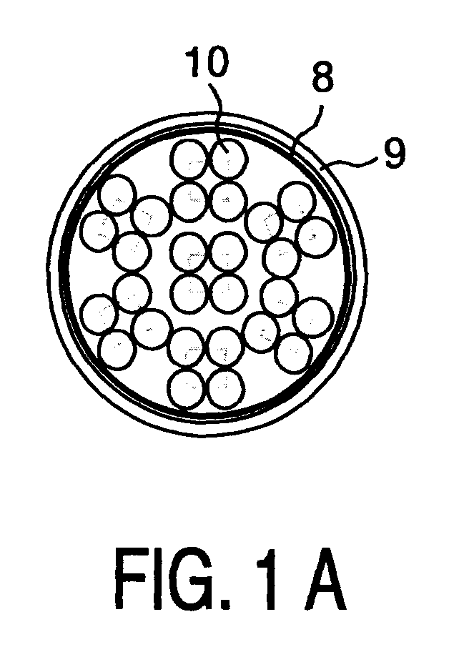
- Figures 1A and 1B show in section two alternative embodiments a cable.
- FIGS. 2A and 2B show, seen in section and laterally, a strand of three fibers.
- FIGS. 3A and 3B represent, seen in section and laterally, a strand of four fibers.
- FIG. 4 represents, seen in section, a strand made of a first layer of three fibers and a second layer of nine fibers.
- the fiber optic cable with lateral light scattering represented by the Figure 1A includes seven identical strands including a central strand surrounded by six others, one of them being designated by 10; each strand is made of four fibers elementary twisted in a helix, which is underlined by the drawing of a square joining the centers of the four fibers of each strand.
- Figure 1B cable includes 18 strands, each made of three elementary fibers twisted in a helix, which is underlined by the drawing of a triangle joining the centers of the three fibers of each strand; there is no central strand.
- a strand of two fibers not shown, obviously comprises two fibers side by side.
- a strand of three fibers shown in Figure 2, consists of fibers 1 to 3, which are twisted to constitute the strand.
- a strand of four fibers is made of fibers 1 to 4, which are twisted to form the strand.
- the fibers here each have a nominal diameter of one millimeter; it could also, in other variants of achievement, be 0.75 mm.
- the fibers are in "PMMA” (Poly Methyl MetAcrylate) with index 1.492: for example the manufacturer's "PG” models “TORAY” can be used.
- the strands are surrounded by a transparent flexible sheet 8 in "Mylar”, and the whole is in turn surrounded by a transparent tubular sheath 9 in "PVC” (Poly Vinyl Chloride) of thickness between 0.7 and 1.2 mm.
- PVC Poly Vinyl Chloride
- the ratio between the pitch of the twisting propeller and the diameter of a strand is preferably between 7 and 19, and even between 10 and 16.
- Figure 4 shows a more complicated strand in which a first layer of three fibers, indicated by a circle 5, is covered with a second layer of nine fibers, indicated by a circle 6. If the fibers constituting the two layers are twisted with substantially the same twisting pitch, the fibers fibers are less stressed than internal fibers, and they emit less light; this is due to a larger radius of curvature which decreases the bending applied to the fibers of the second layer. To make the broadcast of light of all fibers as equal as possible, the ratio between the pitch helix and the diameter of the layer, used to twist the second layer, is different from the one used to twist the first layer. So the radius of curvature due to twisting is substantially the same for all fibers
Landscapes
- Physics & Mathematics (AREA)
- General Physics & Mathematics (AREA)
- Optics & Photonics (AREA)
- Light Guides In General And Applications Therefor (AREA)
- Non-Portable Lighting Devices Or Systems Thereof (AREA)
- Yarns And Mechanical Finishing Of Yarns Or Ropes (AREA)
- Ropes Or Cables (AREA)
Abstract
Description
Claims (9)
- Câble à fibres optiques à diffusion latérale de lumière, comportant au moins un toron fait d'une première couche de fibres élémentaires autour de laquelle peuvent être torsadées d'autres couches de fibres élémentaires, caractérisé en ce que les fibres élémentaires de la première couche d'un toron sont elles-mêmes torsadées, et cette première couche comporte un nombre de fibres élémentaires tel qu'il n'y a pas de fibre élémentaire centrale dans le toron.
- Câble selon la revendication 1, caractérisé en ce que le toron ne comporte que sa première couche.
- Câble selon la revendication 2, caractérisé en ce que les fibres de la première couche sont torsadées avec un rapport entre le pas d'hélice et le diamètre de la première couche compris entre 7 et 19.
- Câble selon la revendication 3, caractérisé en ce que les fibres sont torsadées avec un rapport entre le pas d'hélice et le diamètre de la première couche compris entre 10 et 16.
- Câble selon la revendication 2, caractérisé en ce que le câble comprend sept torons identiques dont un central entouré de six autres.
- Câble selon la revendication 5 caractérisé en ce que chacun des sept torons comprend lui-même quatre fibres.
- Câble selon la revendication 1, dans lequel un toron comporte une première couche de fibres recouverte d'une deuxième couche de fibres, caractérisé en ce que, les fibres constituant la première couche étant torsadées avec un rapport donné entre le pas d'hélice et le diamètre de la couche, les fibres constituant la deuxième couche sont torsadées avec un rapport entre le pas d'hélice et le diamètre de la deuxième couche, différent du susdit rapport donné, de telle façon que le rayon de courbure dû au torsadage soit sensiblement le même pour toutes les fibres.
- Câble selon la revendication 1, dans lequel un toron comporte une première couche de fibres recouverte d'une deuxième couche de fibres, caractérisé en ce que les fibres constituant la deuxième couche sont d'un type différent de celui des fibres de la première couche fibres.
- Câble selon la revendication 1, caractérisé en ce qu'il est entouré d'une feuille souple transparente, le tout à son tour entouré d'une gaine tubulaire transparente.
Applications Claiming Priority (2)
| Application Number | Priority Date | Filing Date | Title |
|---|---|---|---|
| FR9802283 | 1998-02-25 | ||
| FR9802283 | 1998-02-25 |
Publications (2)
| Publication Number | Publication Date |
|---|---|
| EP0939274A2 true EP0939274A2 (fr) | 1999-09-01 |
| EP0939274A3 EP0939274A3 (fr) | 2000-05-24 |
Family
ID=9523357
Family Applications (1)
| Application Number | Title | Priority Date | Filing Date |
|---|---|---|---|
| EP99200451A Withdrawn EP0939274A3 (fr) | 1998-02-25 | 1999-02-16 | Càble à fibres optiques à diffusion latérale de lumière |
Country Status (3)
| Country | Link |
|---|---|
| US (1) | US6169835B1 (fr) |
| EP (1) | EP0939274A3 (fr) |
| JP (1) | JPH11287912A (fr) |
Cited By (1)
| Publication number | Priority date | Publication date | Assignee | Title |
|---|---|---|---|---|
| EP1168025A3 (fr) * | 2000-06-28 | 2002-01-09 | Nexans | Câble ayant une fibre à émission latérale sous gaine de câble transparente ou translucide |
Families Citing this family (7)
| Publication number | Priority date | Publication date | Assignee | Title |
|---|---|---|---|---|
| EP1359248B1 (fr) * | 2002-05-02 | 2009-06-03 | Fatzer AG | Cable lumineux |
| JP4526339B2 (ja) * | 2004-09-15 | 2010-08-18 | シャープ株式会社 | 発光体 |
| US8577197B2 (en) * | 2010-08-17 | 2013-11-05 | Fujikura Ltd. | Heat-resistant optical unit |
| US20140247619A1 (en) * | 2013-03-04 | 2014-09-04 | Corning Incorporated | Light diffusion apparatus and methods for interior space illumination |
| JP6689211B2 (ja) | 2014-06-30 | 2020-04-28 | コーニンクレッカ フィリップス エヌ ヴェKoninklijke Philips N.V. | 生物汚損防止システム |
| US10557968B2 (en) * | 2014-12-16 | 2020-02-11 | Koninklijke Philips N.V. | Marine cable device adapted for the prevention of fouling |
| US10101517B2 (en) * | 2015-02-18 | 2018-10-16 | Corning Incorporated | Optical fiber illumination systems and methods |
Family Cites Families (10)
| Publication number | Priority date | Publication date | Assignee | Title |
|---|---|---|---|---|
| DE2907704B2 (de) * | 1979-02-28 | 1981-03-12 | Siemens AG, 1000 Berlin und 8000 München | Verseilelement für optische Kabel |
| IT1175834B (it) * | 1984-04-19 | 1987-07-15 | Pirelli Cavi Spa | Cavo sottomarino per telecomunicazioni a fibre ottiche |
| JPH0636960Y2 (ja) * | 1988-07-14 | 1994-09-28 | 株式会社アロマック | 光ファイバーを用いた面状発光装飾装置 |
| US5345531A (en) * | 1993-02-26 | 1994-09-06 | Fiberstars, Inc. | Optical fiber lighting apparatus and method |
| US5617497A (en) * | 1993-05-21 | 1997-04-01 | Super Vision International, Inc. | Lateral illumination fiber optic cable device and method of manufacture |
| US5333228A (en) * | 1993-05-21 | 1994-07-26 | Super Vision International Inc. | Lateral illumination fiber optic cable device and method of manufacture |
| JP2781883B2 (ja) | 1995-06-21 | 1998-07-30 | 株式会社マルホン | 遊技機用回転電動役物装置 |
| US5715879A (en) * | 1996-07-15 | 1998-02-10 | Jones; William F. | Nose bar and drive assembly |
| IT1284536B1 (it) * | 1996-09-16 | 1998-05-21 | Pirelli Cavi S P A Ora Pirelli | Cavo ottico per trasmissione dati in reti locali |
| FR2772114A1 (fr) * | 1997-12-09 | 1999-06-11 | Philips Electronics Nv | Cable a fibres optiques a diffusion laterale de lumiere |
-
1999
- 1999-02-16 EP EP99200451A patent/EP0939274A3/fr not_active Withdrawn
- 1999-02-22 US US09/255,629 patent/US6169835B1/en not_active Expired - Fee Related
- 1999-02-25 JP JP11047706A patent/JPH11287912A/ja active Pending
Cited By (1)
| Publication number | Priority date | Publication date | Assignee | Title |
|---|---|---|---|---|
| EP1168025A3 (fr) * | 2000-06-28 | 2002-01-09 | Nexans | Câble ayant une fibre à émission latérale sous gaine de câble transparente ou translucide |
Also Published As
| Publication number | Publication date |
|---|---|
| US6169835B1 (en) | 2001-01-02 |
| JPH11287912A (ja) | 1999-10-19 |
| EP0939274A3 (fr) | 2000-05-24 |
Similar Documents
| Publication | Publication Date | Title |
|---|---|---|
| EP0937270B1 (fr) | Cable de telecommunication a fibres optiques | |
| EP0559567B1 (fr) | Procédés de fabrication d'un conducteur optique cylindrique multiguides pour câble de télécommunications | |
| EP0611973B1 (fr) | Guides optiques multicoeurs de grande précision et de petites dimensions et procédé de fabrication de ces guides | |
| CA1119856A (fr) | Elements de cable a fibres optiques et cables les incorporant | |
| FR2676286A1 (fr) | Dispositif de branchement pour cables a fibres optiques. | |
| RU2002113650A (ru) | Оптические волокна на основе кольцевого фотонного кристалла | |
| EP0822432A1 (fr) | Multi-ruban de fibres optiques | |
| CA2242707A1 (fr) | Cable a fibres optiques et conducteurs metalliques | |
| EP0902310B1 (fr) | Structures de câbles à fibres optiques autorésistantes à la compression | |
| FR2543729A1 (fr) | Cable composite pour la transmission de signaux de haute frequence et de signaux optiques | |
| US6169835B1 (en) | Optical fiber cable with lateral light diffusion | |
| FR2722305A1 (fr) | Dispositif d'eclairage d'afficheur a cristaux liquides et son procede de fabrication | |
| EP0637768A1 (fr) | Câble à fibres optiques et procédé de réalisation associé | |
| US20060165358A1 (en) | Compact bundles of light guides with sections having reduced interstitial area | |
| EP0715192A1 (fr) | Procédé de couplage entre une fibre optique multicoeurs et plusieurs fibres optiques monocoeurs | |
| FR2744809A1 (fr) | Cable a fibres optiques sans elements de renfort | |
| FR2766583A1 (fr) | Fibre optique multicoeurs | |
| KR910021230A (ko) | 내시경 | |
| EP0718648A1 (fr) | Procédé de fabrication d'un répartiteur optique multifibre et répartiteur optique obtenu selon ce procédé | |
| EP0558600B1 (fr) | Dispositif pour emettre de la lumiere a l'aide d'une fibre optique, et procede de mise en uvre de ce dispositif | |
| US20030156814A1 (en) | Optical fiber block having semicircular grooves and method for same | |
| CA2227029C (fr) | Cable comportant des fibres optiques entourees par une gaine externe | |
| FR2803666A1 (fr) | Cable optique adapte au(x) piquage(s) | |
| FR2761482A1 (fr) | Fibre optique multicoeurs perfectionnee et procede de fabrication | |
| FR2622306A1 (fr) | Procede de couplage de fibres optiques |
Legal Events
| Date | Code | Title | Description |
|---|---|---|---|
| PUAI | Public reference made under article 153(3) epc to a published international application that has entered the european phase |
Free format text: ORIGINAL CODE: 0009012 |
|
| AK | Designated contracting states |
Kind code of ref document: A2 Designated state(s): DE FR GB |
|
| AX | Request for extension of the european patent |
Free format text: AL;LT;LV;MK;RO;SI |
|
| PUAL | Search report despatched |
Free format text: ORIGINAL CODE: 0009013 |
|
| AK | Designated contracting states |
Kind code of ref document: A3 Designated state(s): AT BE CH CY DE DK ES FI FR GB GR IE IT LI LU MC NL PT SE |
|
| AX | Request for extension of the european patent |
Free format text: AL;LT;LV;MK;RO;SI |
|
| 17P | Request for examination filed |
Effective date: 20001124 |
|
| AKX | Designation fees paid |
Free format text: DE FR GB |
|
| STAA | Information on the status of an ep patent application or granted ep patent |
Free format text: STATUS: THE APPLICATION IS DEEMED TO BE WITHDRAWN |
|
| 18D | Application deemed to be withdrawn |
Effective date: 20080624 |