EP0939472A2 - Lichtbogenfehlerdetektor mit Schutz gegen unbeabsichtigtes Auslösen und diese Vorrichtung enthaltende Schutzschalter - Google Patents
Lichtbogenfehlerdetektor mit Schutz gegen unbeabsichtigtes Auslösen und diese Vorrichtung enthaltende Schutzschalter Download PDFInfo
- Publication number
- EP0939472A2 EP0939472A2 EP99103474A EP99103474A EP0939472A2 EP 0939472 A2 EP0939472 A2 EP 0939472A2 EP 99103474 A EP99103474 A EP 99103474A EP 99103474 A EP99103474 A EP 99103474A EP 0939472 A2 EP0939472 A2 EP 0939472A2
- Authority
- EP
- European Patent Office
- Prior art keywords
- pulses
- amplitude
- pulse
- peak detector
- conditioned
- Prior art date
- Legal status (The legal status is an assumption and is not a legal conclusion. Google has not performed a legal analysis and makes no representation as to the accuracy of the status listed.)
- Withdrawn
Links
Images
Classifications
-
- H—ELECTRICITY
- H02—GENERATION; CONVERSION OR DISTRIBUTION OF ELECTRIC POWER
- H02H—EMERGENCY PROTECTIVE CIRCUIT ARRANGEMENTS
- H02H1/00—Details of emergency protective circuit arrangements
- H02H1/0007—Details of emergency protective circuit arrangements concerning the detecting means
- H02H1/0015—Using arc detectors
-
- H—ELECTRICITY
- H02—GENERATION; CONVERSION OR DISTRIBUTION OF ELECTRIC POWER
- H02H—EMERGENCY PROTECTIVE CIRCUIT ARRANGEMENTS
- H02H1/00—Details of emergency protective circuit arrangements
- H02H1/04—Arrangements for preventing response to transient abnormal conditions, e.g. to lightning or to short duration over voltage or oscillations; Damping the influence of DC component by short circuits in AC networks
Definitions
- This invention relates to detection and interruption of currents and circuits experiencing arc faults. More particularly, it relates to an arc fault detector and a circuit breaker incorporating such an arc fault detector which minimize the effects of other phenomena such as the burnout of tungsten bulbs, which can falsely provide an indication of an arc fault.
- Arc faults can occur in electrical systems for instance between adjacent bared conductors, between exposed ends of broken conductors, at a faulty connection, and in other situations where conducting elements are in close proximity.
- Arc faults in ac systems can be intermittent as the magnetic repulsion forces generated by the arc current force the conductors apart to extinguish the arc. Mechanical forces then bring the conductors together again so that another arc is struck.
- Arc faults typically have high resistance so that the arc current is below the instantaneous or magnetic trip thresholds of conventional circuit breakers. Also, the intermittent nature of an arc fault can create an average RMS current value which is below the thermal threshold for such circuit breakers. Even so, the arcs can cause damage or start a fire if they occur near combustible material. It is not practical to simply lower the pickup currents on conventional circuit breakers as there are many typical loads which draw similar currents, and would therefore, cause nuisance trips.
- arc condition which can occur in a protected circuit to which it is desired that the arc fault circuit not respond.
- This is an arc created by the burnout of a tungsten filament such as in a light bulb. When the filament burns through, a small gap is created between the burned out ends of the filament. An arc is struck across this gap and can quickly envelop the entire filament so that it extends between the two conductors thereby drawing a very large arc current.
- tungsten bulbs are provided with a small fuse in the base. Even so, burnout of the filament and blowing of the fuse results typically in a pair of current pulses of opposite polarity.
- This pair of pulses can be of sufficient magnitude that the threshold value of the time attenuated accumulation of pulses in the circuit breaker described in US Patent No. 5,691,869 is exceeded and the circuit breaker is tripped. This is considered a nuisance trip as the fuse has interrupted the arc.
- Tungsten filament bulbs can also generate false trips when used with a dimmer.
- a dimmer which is phased back can generate repetitive step increases in current on each half cycle.
- the circuit breaker can be set so that the threshold of the time attenuated accumulation of pulses generated by the dimmer do not reach the trip level with normal loads.
- the cold filament has a very low resistance and can draw up to fifteen times normal current. This can result in a nuisance trip when a tungsten lamp controlled by a dimmer switch is first turned on.
- arc fault detector and circuit breakers incorporating such arc fault detectors which are derived from recognition that pulses generated by tungsten bulbs are normally not only large in amplitude, but are also longer in duration than the pulses generated by true arc faults.
- pulse conditioning means is provided which not only limits the amplitude of the pulses generated by the pulse generator but also stretches the pulses generated by the pulse generating means to reduce variations in duration of the pulses that are applied to the means generating the trip signal.
- the trip means which generates a time attenuated accumulation of the conditioned pulses only responds to conditioned pulses having an amplitude above a predetermined threshold amplitude.
- the pulse conditioning means limits the amplitude of the conditioned pulses to a selected amplitude which is above the threshold amplitude.
- the peak detector has a time constant which is selected to provide a predetermined pulse duration for a conditioned pulse to decay in amplitude from the selected amplitude to the predetermined threshold amplitude.
- this predetermined pulse duration is about one half cycle of the ac system.
- the peak detector comprises a peak detector capacitor to which pulses from the pulse generating means are applied through a first resistor and a second resistor shunting the capacitor.
- a diode between the pulse generating means and the peak detector capacitor prevents discharge of the capacitor through the pulse generating means.
- the means limiting the conditioned pulses to the selected amplitude is a zener diode connected in parellel with the peak detector capacitor between the first resistor and the peak detector capacitor.
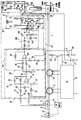
- the Figure illustrates an arc fault circuit breaker 1 in accordance with the invention providing protection for an electrical circuit 3 which includes a line conductor 5 and a neutral conductor 7.
- the circuit breaker 1 provides overcurrent and short circuit protection, arc fault protection and ground fault protection for the electrical system 3.
- Overcurrent and short circuit protection are provided by the conventional thermal-magnetic trip mechanism (not shown) which includes a bimetal 11.
- the bimetal responds to persistent overcurrent conditions to actuate a spring-powered operating mechanism 9 to open a set of separable contacts 13 connected in series with the line conductor 5 to interrupt current flow in the electrical system.
- Ground fault protection is provided by a ground fault circuit 15.
- the ground fault circuit 15 shown is the well known dormant oscillator type which utilizes two sensing coils 17 and 19 which sense current in the line and neutral conductors 5 and 7.
- the ground fault circuit 15 In response to a line to ground or a neutral to ground fault, the ground fault circuit 15 generates a ground fault trip signal which turns on the silicon controlled rectifier (SCR) 21.
- SCR silicon controlled rectifier
- This energizes a trip solenoid 23 connected by the SCR 21 between the neutral conductor 7 and circuit breaker common which is referenced to the line conductor through the lead 24.
- a resistor 25 limits the current through the coil 23 and a capacitor 27 protects the gate of the SCR 21 from being falsely tripped on noise.
- Arc fault protection is provided by an arc fault circuit 29.
- This arc fault circuit 29 utilizes a pair of leads 31 connected across the bimetal 11 to sense current in the protected electrical system 3. As taught by US Patent No. 5,519,561, as the resistance of the bimetal 11 is known, the voltage drop across this bimetal provides a measure of the current flowing in the line conductor 5.
- the arc fault circuit 29 also includes a pulse generator 33, a circuit 35 which provides a time attenuated accumulation of the pulses generated by the pulse generator 33, and an output circuit 37 which provides a trip signal which through the lead 39 turns on the SCR at 21 to open the separable contacts 13 in the same manner as the ground fault circuit 15.
- the pulse generator 33 includes a high pass filter 41 formed by the series connected capacitor 43 and resistor 45, followed by a low pass filter 47 formed by the parallel connected capacitor 49 and resistor 51.
- the high pass filter 41 and low pass filter 47 have a band pass in a range which generates pulses in response to the step increases in current caused by striking of an arc and yet is below any carrier frequencies that may be on the power line.
- this pass band is in a range of about 290 to 1,540 Hz for the 3 db points and could go up to 10 KHz or more.
- An operational amplifier (op amp) 53 provides gain for the pulses.
- a capacitor 54 reduces high frequency noise in the pulses.
- the op amp 53 is biased at its non-inverting input by a 13 vdc supply voltage.
- a resistor 55 and capacitor 57 delay application of the bias to prevent false trip signals during power up.
- the positive and negative pulses generated by the band pass filter ride on the plus 13 vdc volt bias applied to the op amp 53.
- This bias is removed by the ac coupling capacitor 59 which along with the resistor 61 forms another high pass filter stage.
- the bi-polar pulse signal resulting is rectified by a rectifier circuit 63 which includes another op amp 65.
- Positive pulses are applied to the non-inverting input of the op amp 65 through the diode 67 while negative pulses are applied to the inverting input through the diode 69.
- the output of the op amp 65 is a pulse signal having pulses of a single polarity.
- the circuit 35 generates a time attenuated accumulation of the pulses in the pulse signal generated by the pulse generator 33.
- the pulses are accumulated on a capacitor 71 connected to the 26 vdc supply.
- a bleed resistor 73 connected across the capacitor provides the time attenuation.
- the pulses are applied to the capacitor 71 through a differential amplifier formed by the pair of transistors 75a and 75b. When no pulses are generated, both electrodes of the capacitor 71 are at 26 volts.
- the pulses from the pulse generator 33 provide base drive current for the transistor 75a.
- a voltage divider formed by the resistor 77 and 79 connected at their midpoint to the base of the transistor 75b set the minimum amplitude for the pulses to turn on the transistor 75a.
- the transistor 75b In the absence of pulses, the transistor 75b is on which holds the transistor 75a off due to the voltage developed across the resistor 80. When the amplitude of a pulse exceeds the threshold, the transistor 75a is turned on (which turns the transistor 75b off).
- This threshold is selected so that pulses which could be generated by some normal loads, such as for instance a dimmer switch operating at normal loads, are not accumulated.
- the amplitude of the pulses is set by the gain of the op amp 65 which in turn is determined by the ratio of the feed back resistor 81 and input resistor 83.
- the amplitude and duration of each pulse determine the amount of charge which is applied to the capacitor 71. The successive pulses are accumulated through the summation of the charge they add to the capacitor 71.
- the resistor 73 continuously bleeds the charge on the capacitor 71 with a time constant determined by the values of the capacitor 71 and resistor 73 to time attenuate the accumulation of the pulses. It can be appreciated that the magnitude and time interval between pulses determines the instantaneous voltage that appears across the capacitor 71.
- the output circuit 37 monitors the voltage across the capacitor 71 representing the time attenuated accumulation of the pulses in the pulse signal generated by the pulse generator. Each pulse lowers the voltage on the capacitor which is applied to the base of a transistor 85 in the output circuit. A voltage is applied to the emitter of the transistor 85 by the 13 vdc supply through a resistor 87 and diode 89. With no pulses being generated, the voltage on the base of the transistor 85 is 26 volts. Without the diode 89, the 13 volt reverse bias would destroy the base to emitter junction of the transistor 85. The diode 89 withstands this voltage.
- the transistor 85 When the voltage at the lower end of the capacitor 71, and therefore on the base of the transistor 85, falls below the 13 volts minus the forward drop across the diode 89, the transistor 85 is turned on. Feedback provided through the lead 91 and the resistors 93 and 95 holds the transistor 85 on by providing a continuous output of the op amp 65 which holds the transistor 75a on. Turn on of the transistor 85 provides base drive current for the transistor 97 which draws current limited by the resistor 99 to generate an arc fault trip signal which turns on the SCR 21 and trips the separable contacts 13 open.
- burnout of a tungsten bulb 101 energized by the electrical system 3 protected by the circuit breaker 1 can generate, typically, two large amplitude pulses in consecutive half cycles which can by themselves accumulate sufficient charge on the capacitor 71 to reduce the voltage on the base of the transistor 85 to the threshold voltage which generates the trip signal.
- turn on of a cold tungsten bulb controlled by a dimmer can also produce large initial pulses which can accumulate sufficient charge on the capacitor 71 to generate a trip signal.
- a pulse conditioner 105 modifies the pulses output by the full wave rectifier 63.
- This pulse conditioner 105 conditions the pulses in two respects. First, it limits the amplitude of the pulses and second, it stretches the pulses to reduce variations in pulse duration. As the pulses generated by the two tungsten bulb phenomena tend to be greater in amplitude and wider than the pulses generated by true arcs, this conditioning of the pulses reduces the contribution to charge accumulation on the capacitor 71 produced by the tungsten bulb effects.
- tungsten bulb burn out typically only produces two pulses and cold turn on of the tungsten bulb only produces a couple of large pulses before the filament warms up, while true arcs continue to randomly generate pulses, the parameters can be set to ignore tungsten bulb phenomena and still respond quickly to arc faults.
- Limiting of pulse amplitude is provide by a zener diode 107.
- the breaker over voltage of the zener diode 107 is selected to be above the threshold voltage required to turn on the transistor 75a but less than the amplitude that is typically generated by tungsten bulb burn out or cold turn on.
- Stretching of the pulses is provided by pulse stretching circuit 109.
- the pulse stretching circuit 109 includes a capacitor 111 connected between the output of the pulse generator 33 and ground. The pulses from the pulse generator are applied to the capacitor 111 through a first resistor 113. A second resistor 115 connected in shunt bleeds charge from the capacitor 111. A diode 117 prevents discharge of the capacitor 111 back through the rectifier 63 of the pulse generator.
- This pulse stretching circuit 109 forms a peak detector having a time constant which is determined by the values of the capacitor 111 and the resistor 115.
- This time constant is selected such that a pulse from the pulse generator 35 having an amplitude equal to the selected limiting voltage set by the zener diode 107 will decay to the threshold voltage set by the resistors 77 and 79 in about one half cycle, i.e., about 8.3 milliseconds in a 60 cycle system.
- the time constant was selected to be about 23 milliseconds.
- This time constant combined with the clipping provided by the zener diode 107 and the threshold set by the resistors 77 and 79 stretches a 70 amp peak arc current to about a full half cycle of integration conduction on the capacitor 71.
- Tungsten bulb burn out produces a pair of pulses one half cycle apart which are much larger than the limit set by the zener diode, e.g., about twice as large. These pulses also have a certain time that they remain above the clipping voltage so that the capacitor 111 remains charged and only begins to discharge when the pulse voltage falls below the clipping voltage set by the zener diode 107. Therefore, a pulse generated by tungsten burn out will tend to last longer than a half cycle by the time that it remains above the clipping voltage.
- the second pulse will occur before the first pulse has decayed to the threshold voltage, and hence the integration capacitor 71 will be continuously charged until the second pulse terminates.
- the total integration time for these pulses will be two half cycles plus the additional time that the second pulse remains above the clipping voltage.
- the trip circuit can be set to trip on a third arc fault pulse which has an amplitude of at least about the clipping voltage. Pulses generated by the step changes in current produced by smaller arc faults which exceed the threshold voltage but not the clipping voltage are also stretched, but not to a full half cycle. However, since the pulses generated by a tungsten bulb are not stretched proportionately as much as pulses generated by arc faults, the arc fault detector of the invention can be made to trip sooner on arc faults without generating false trips in response to tungsten bulb burn out and cold turn on when dimmer controlled.
Landscapes
- Engineering & Computer Science (AREA)
- Power Engineering (AREA)
- Emergency Protection Circuit Devices (AREA)
- Circuit Arrangement For Electric Light Sources In General (AREA)
- Keying Circuit Devices (AREA)
- Testing Electric Properties And Detecting Electric Faults (AREA)
- Breakers (AREA)
Applications Claiming Priority (2)
| Application Number | Priority Date | Filing Date | Title |
|---|---|---|---|
| US09/030,990 US5896262A (en) | 1998-02-26 | 1998-02-26 | Arc fault detector with protection against nuisance trips and circuit breaker incorporating same |
| US30990 | 1998-02-26 |
Publications (2)
| Publication Number | Publication Date |
|---|---|
| EP0939472A2 true EP0939472A2 (de) | 1999-09-01 |
| EP0939472A3 EP0939472A3 (de) | 2000-05-10 |
Family
ID=21857063
Family Applications (1)
| Application Number | Title | Priority Date | Filing Date |
|---|---|---|---|
| EP99103474A Withdrawn EP0939472A3 (de) | 1998-02-26 | 1999-02-23 | Lichtbogenfehlerdetektor mit Schutz gegen unbeabsichtigtes Auslösen und diese Vorrichtung enthaltende Schutzschalter |
Country Status (6)
| Country | Link |
|---|---|
| US (1) | US5896262A (de) |
| EP (1) | EP0939472A3 (de) |
| JP (1) | JPH11289655A (de) |
| AU (1) | AU748157B2 (de) |
| BR (1) | BR9900514A (de) |
| CA (1) | CA2263009A1 (de) |
Cited By (3)
| Publication number | Priority date | Publication date | Assignee | Title |
|---|---|---|---|---|
| EP1126572A2 (de) | 2000-02-14 | 2001-08-22 | Eaton Corporation | Lichtbogenfehlerdetektor, der auf Momentanstrom und Stromschritte reagiert, sowie diese Einheit enthaltender Schutzschalter |
| WO2005086308A1 (de) * | 2004-03-04 | 2005-09-15 | Siemens Aktiengesellschaft | Drei- oder vierpoliger niederspannungs-leistungsschalter mit als stromsensoren dienenden rogowskispulen |
| US7460346B2 (en) | 2005-03-24 | 2008-12-02 | Honeywell International Inc. | Arc fault detection and confirmation using voltage and current analysis |
Families Citing this family (37)
| Publication number | Priority date | Publication date | Assignee | Title |
|---|---|---|---|---|
| US6532424B1 (en) | 1995-03-13 | 2003-03-11 | Square D Company | Electrical fault detection circuit with dual-mode power supply |
| US6313641B1 (en) | 1995-03-13 | 2001-11-06 | Square D Company | Method and system for detecting arcing faults and testing such system |
| US6259996B1 (en) | 1998-02-19 | 2001-07-10 | Square D Company | Arc fault detection system |
| US6242993B1 (en) | 1995-03-13 | 2001-06-05 | Square D Company | Apparatus for use in arcing fault detection systems |
| US6377427B1 (en) | 1995-03-13 | 2002-04-23 | Square D Company | Arc fault protected electrical receptacle |
| US6246556B1 (en) | 1995-03-13 | 2001-06-12 | Square D Company | Electrical fault detection system |
| US5933308A (en) * | 1997-11-19 | 1999-08-03 | Square D Company | Arcing fault protection system for a switchgear enclosure |
| US6625550B1 (en) | 1998-02-19 | 2003-09-23 | Square D Company | Arc fault detection for aircraft |
| US6621669B1 (en) | 1998-02-19 | 2003-09-16 | Square D Company | Arc fault receptacle with a feed-through connection |
| US6567250B1 (en) | 1998-02-19 | 2003-05-20 | Square D Company | Arc fault protected device |
| US6782329B2 (en) | 1998-02-19 | 2004-08-24 | Square D Company | Detection of arcing faults using bifurcated wiring system |
| US6477021B1 (en) | 1998-02-19 | 2002-11-05 | Square D Company | Blocking/inhibiting operation in an arc fault detection system |
| US6275044B1 (en) | 1998-07-15 | 2001-08-14 | Square D Company | Arcing fault detection system |
| US6218844B1 (en) | 1998-12-16 | 2001-04-17 | Square D Company | Method and apparatus for testing an arcing fault circuit interrupter |
| US6259340B1 (en) * | 1999-05-10 | 2001-07-10 | General Electric Company | Circuit breaker with a dual test button mechanism |
| KR100423886B1 (ko) * | 2000-05-12 | 2004-03-24 | 휴먼엘텍 주식회사 | 아크 결함 보호용 차단기 및 이를 구비하는 회로 차단기 |
| US7068480B2 (en) | 2001-10-17 | 2006-06-27 | Square D Company | Arc detection using load recognition, harmonic content and broadband noise |
| US7151656B2 (en) | 2001-10-17 | 2006-12-19 | Square D Company | Arc fault circuit interrupter system |
| US7136265B2 (en) * | 2001-10-17 | 2006-11-14 | Square D Company | Load recognition and series arc detection using bandpass filter signatures |
| US6717786B2 (en) | 2001-10-30 | 2004-04-06 | The Boeing Company | Automatic voltage source selector for circuit breakers utilizing electronics |
| US6724591B2 (en) | 2001-11-15 | 2004-04-20 | Eaton Corporation | Circuit interrupter employing a mechanism to open a power circuit in response to a resistor body burning open |
| US6639768B2 (en) | 2001-12-20 | 2003-10-28 | Eaton Corporation | Arc fault detector immune to dimmer transients and a circuit breaker incorporating the same |
| US7106069B2 (en) * | 2002-11-15 | 2006-09-12 | Human El-Tech, Inc. | Apparatus for detecting arc fault |
| US7492562B2 (en) * | 2003-09-10 | 2009-02-17 | Siemens Energy & Automation, Inc. | AFCI temperature compensated current sensor |
| US7149066B2 (en) * | 2003-10-07 | 2006-12-12 | Eaton Corporation | Fault detector for two line power distribution system and protection apparatus incorporating the same |
| US7359167B2 (en) * | 2005-02-15 | 2008-04-15 | Eaton Corporation | Corded leakage-current detection and interruption apparatus |
| US7253637B2 (en) | 2005-09-13 | 2007-08-07 | Square D Company | Arc fault circuit interrupter system |
| US20070132531A1 (en) * | 2005-12-14 | 2007-06-14 | Eaton Corporation | Two pole circuit interrupter employing a single arc fault or ground fault trip circuit |
| US7486492B2 (en) * | 2006-01-18 | 2009-02-03 | Eaton Corporation | Electrical switching apparatus including a second trip circuit responding to failure of a first trip circuit to provide a repetitive signal |
| US7441173B2 (en) * | 2006-02-16 | 2008-10-21 | Siemens Energy & Automation, Inc. | Systems, devices, and methods for arc fault detection |
| US20070208520A1 (en) * | 2006-03-01 | 2007-09-06 | Siemens Energy & Automation, Inc. | Systems, devices, and methods for arc fault management |
| US7499250B2 (en) * | 2006-04-19 | 2009-03-03 | Siemens Energy & Automation, Inc. | Systems, devices, and methods for temperature compensation in arc fault detection systems |
| US8749327B2 (en) * | 2008-09-18 | 2014-06-10 | General Electric Company | Circuit interrupter trip apparatus and method |
| US8228649B2 (en) * | 2009-06-04 | 2012-07-24 | Eaton Corporation | Impedance-based current sensor |
| RU2654046C2 (ru) | 2013-09-30 | 2018-05-16 | ШНЕЙДЕР ЭЛЕКТРИК ЮЭсЭй, ИНК. | Распределенная защита от дугового пробоя между выводным устройством и прерывателем цепи |
| US12081011B2 (en) | 2017-05-23 | 2024-09-03 | Pass & Seymour, Inc. | Arc fault circuit interrupter |
| GB2624399A (en) * | 2022-11-16 | 2024-05-22 | Eaton Intelligent Power Ltd | Circuit breaker with current measuring capability |
Family Cites Families (9)
| Publication number | Priority date | Publication date | Assignee | Title |
|---|---|---|---|---|
| US3996499A (en) * | 1974-09-09 | 1976-12-07 | Westinghouse Electric Corporation | Zener diode effect on long acceleration module |
| ZA926652B (en) * | 1991-09-26 | 1993-03-16 | Westinghouse Electric Corp | Circuit breaker with protection against sputtering arc faults |
| US5224006A (en) * | 1991-09-26 | 1993-06-29 | Westinghouse Electric Corp. | Electronic circuit breaker with protection against sputtering arc faults and ground faults |
| US5519561A (en) * | 1994-11-08 | 1996-05-21 | Eaton Corporation | Circuit breaker using bimetal of thermal-magnetic trip to sense current |
| US5682101A (en) * | 1995-03-13 | 1997-10-28 | Square D Company | Arcing fault detection system |
| US5590012A (en) * | 1995-03-30 | 1996-12-31 | Siemens Energy & Automation, Inc. | Electric arc detector sensor circuit |
| US5691869A (en) * | 1995-06-06 | 1997-11-25 | Eaton Corporation | Low cost apparatus for detecting arcing faults and circuit breaker incorporating same |
| US5818237A (en) * | 1996-06-10 | 1998-10-06 | Eaton Corporation | Apparatus for envelope detection of low current arcs |
| US5805398A (en) * | 1997-09-29 | 1998-09-08 | Eaton Corporation | Arc fault detector with immunity to tungsten bulb burnout and circuit breaker incorporating same |
-
1998
- 1998-02-26 US US09/030,990 patent/US5896262A/en not_active Expired - Lifetime
-
1999
- 1999-02-23 EP EP99103474A patent/EP0939472A3/de not_active Withdrawn
- 1999-02-24 JP JP11047016A patent/JPH11289655A/ja active Pending
- 1999-02-24 AU AU18395/99A patent/AU748157B2/en not_active Ceased
- 1999-02-24 BR BR9900514-0A patent/BR9900514A/pt not_active IP Right Cessation
- 1999-02-25 CA CA002263009A patent/CA2263009A1/en not_active Abandoned
Cited By (6)
| Publication number | Priority date | Publication date | Assignee | Title |
|---|---|---|---|---|
| EP1126572A2 (de) | 2000-02-14 | 2001-08-22 | Eaton Corporation | Lichtbogenfehlerdetektor, der auf Momentanstrom und Stromschritte reagiert, sowie diese Einheit enthaltender Schutzschalter |
| EP1126572A3 (de) * | 2000-02-14 | 2005-10-05 | Eaton Corporation | Lichtbogenfehlerdetektor, der auf Momentanstrom und Stromschritte reagiert, sowie diese Einheit enthaltender Schutzschalter |
| WO2005086308A1 (de) * | 2004-03-04 | 2005-09-15 | Siemens Aktiengesellschaft | Drei- oder vierpoliger niederspannungs-leistungsschalter mit als stromsensoren dienenden rogowskispulen |
| US7309993B2 (en) | 2004-03-04 | 2007-12-18 | Siemens Aktiengesellschaft | Three- or four-pole low-voltage power switch with Rogowski coils operating as current sensors |
| CN100550554C (zh) * | 2004-03-04 | 2009-10-14 | 西门子公司 | 具有罗果夫斯基线圈的三极或四极低压功率开关 |
| US7460346B2 (en) | 2005-03-24 | 2008-12-02 | Honeywell International Inc. | Arc fault detection and confirmation using voltage and current analysis |
Also Published As
| Publication number | Publication date |
|---|---|
| JPH11289655A (ja) | 1999-10-19 |
| EP0939472A3 (de) | 2000-05-10 |
| BR9900514A (pt) | 2000-01-18 |
| AU1839599A (en) | 1999-09-09 |
| AU748157B2 (en) | 2002-05-30 |
| CA2263009A1 (en) | 1999-08-26 |
| US5896262A (en) | 1999-04-20 |
Similar Documents
| Publication | Publication Date | Title |
|---|---|---|
| US5896262A (en) | Arc fault detector with protection against nuisance trips and circuit breaker incorporating same | |
| US5805398A (en) | Arc fault detector with immunity to tungsten bulb burnout and circuit breaker incorporating same | |
| CA2248491C (en) | Arc fault detector with limiting of sensed signal to shape response characteristic and circuit breaker incorporating same | |
| EP1126572B1 (de) | Lichtbogenfehlerdetektor, der auf Momentanstrom und Stromschritte reagiert, sowie diese Einheit enthaltender Schutzschalter | |
| US5963405A (en) | Low cost apparatus for detecting arcing faults and circuit breaker incorporating same | |
| US5818237A (en) | Apparatus for envelope detection of low current arcs | |
| CA2267005C (en) | Test circuit for verifying operation of an arc fault detector | |
| EP0712193B1 (de) | Schutzschalter mit Bimetall des magnetothermischen Auslösers als Stromsensor | |
| US6522509B1 (en) | Arc fault detection in ac electric power systems | |
| CA2248486C (en) | Apparatus for detecting arcing faults and ground faults in multiwire branch electric power circuits | |
| US6229679B1 (en) | Arc fault circuit interrupter without DC supply | |
| US7636225B2 (en) | Arc detection circuit | |
| EP0981193A2 (de) | Lichtbogenempfindliche Vorrichtung zur Erkennung von Hülkurven von Schwachstromlichtbogen | |
| MXPA99001865A (en) | Arc failure detector with protection against disturbance and circuit circuit that incorporates it |
Legal Events
| Date | Code | Title | Description |
|---|---|---|---|
| PUAI | Public reference made under article 153(3) epc to a published international application that has entered the european phase |
Free format text: ORIGINAL CODE: 0009012 |
|
| AK | Designated contracting states |
Kind code of ref document: A2 Designated state(s): DE FR GB IT |
|
| AX | Request for extension of the european patent |
Free format text: AL;LT;LV;MK;RO;SI |
|
| RIN1 | Information on inventor provided before grant (corrected) |
Inventor name: ELMS, ROBERT TRACY Inventor name: NATILI, THOMAS EDWARD, EATON CORPORATION Inventor name: RAE, THOMAS CHRISTOPHER |
|
| PUAL | Search report despatched |
Free format text: ORIGINAL CODE: 0009013 |
|
| AK | Designated contracting states |
Kind code of ref document: A3 Designated state(s): AT BE CH CY DE DK ES FI FR GB GR IE IT LI LU MC NL PT SE |
|
| AX | Request for extension of the european patent |
Free format text: AL;LT;LV;MK;RO;SI |
|
| 17P | Request for examination filed |
Effective date: 20001110 |
|
| AKX | Designation fees paid |
Free format text: DE FR GB IT |
|
| STAA | Information on the status of an ep patent application or granted ep patent |
Free format text: STATUS: THE APPLICATION IS DEEMED TO BE WITHDRAWN |
|
| 18D | Application deemed to be withdrawn |
Effective date: 20050901 |