EP0939476B2 - Dispositif pour l'alimentation centrale d'un éclairage de sécurité - Google Patents
Dispositif pour l'alimentation centrale d'un éclairage de sécurité Download PDFInfo
- Publication number
- EP0939476B2 EP0939476B2 EP99103538A EP99103538A EP0939476B2 EP 0939476 B2 EP0939476 B2 EP 0939476B2 EP 99103538 A EP99103538 A EP 99103538A EP 99103538 A EP99103538 A EP 99103538A EP 0939476 B2 EP0939476 B2 EP 0939476B2
- Authority
- EP
- European Patent Office
- Prior art keywords
- voltage
- lights
- stand
- light
- lighting
- Prior art date
- Legal status (The legal status is an assumption and is not a legal conclusion. Google has not performed a legal analysis and makes no representation as to the accuracy of the status listed.)
- Expired - Lifetime
Links
Images

Classifications
-
- H—ELECTRICITY
- H05—ELECTRIC TECHNIQUES NOT OTHERWISE PROVIDED FOR
- H05B—ELECTRIC HEATING; ELECTRIC LIGHT SOURCES NOT OTHERWISE PROVIDED FOR; CIRCUIT ARRANGEMENTS FOR ELECTRIC LIGHT SOURCES, IN GENERAL
- H05B41/00—Circuit arrangements or apparatus for igniting or operating discharge lamps
- H05B41/14—Circuit arrangements
- H05B41/36—Controlling
- H05B41/38—Controlling the intensity of light
- H05B41/40—Controlling the intensity of light discontinuously
-
- H—ELECTRICITY
- H02—GENERATION; CONVERSION OR DISTRIBUTION OF ELECTRIC POWER
- H02J—ELECTRIC POWER NETWORKS; CIRCUIT ARRANGEMENTS OR SYSTEMS FOR SUPPLYING OR DISTRIBUTING ELECTRIC POWER; SYSTEMS FOR STORING ELECTRIC ENERGY
- H02J9/00—Circuit arrangements for emergency or stand-by power supply, e.g. for emergency lighting
- H02J9/02—Circuit arrangements for emergency or stand-by power supply, e.g. for emergency lighting in which an auxiliary distribution system and its associated lamps are brought into service
-
- H—ELECTRICITY
- H05—ELECTRIC TECHNIQUES NOT OTHERWISE PROVIDED FOR
- H05B—ELECTRIC HEATING; ELECTRIC LIGHT SOURCES NOT OTHERWISE PROVIDED FOR; CIRCUIT ARRANGEMENTS FOR ELECTRIC LIGHT SOURCES, IN GENERAL
- H05B41/00—Circuit arrangements or apparatus for igniting or operating discharge lamps
- H05B41/14—Circuit arrangements
- H05B41/36—Controlling
-
- H—ELECTRICITY
- H05—ELECTRIC TECHNIQUES NOT OTHERWISE PROVIDED FOR
- H05B—ELECTRIC HEATING; ELECTRIC LIGHT SOURCES NOT OTHERWISE PROVIDED FOR; CIRCUIT ARRANGEMENTS FOR ELECTRIC LIGHT SOURCES, IN GENERAL
- H05B47/00—Circuit arrangements for operating light sources in general, i.e. where the type of light source is not relevant
- H05B47/10—Controlling the light source
-
- Y—GENERAL TAGGING OF NEW TECHNOLOGICAL DEVELOPMENTS; GENERAL TAGGING OF CROSS-SECTIONAL TECHNOLOGIES SPANNING OVER SEVERAL SECTIONS OF THE IPC; TECHNICAL SUBJECTS COVERED BY FORMER USPC CROSS-REFERENCE ART COLLECTIONS [XRACs] AND DIGESTS
- Y02—TECHNOLOGIES OR APPLICATIONS FOR MITIGATION OR ADAPTATION AGAINST CLIMATE CHANGE
- Y02B—CLIMATE CHANGE MITIGATION TECHNOLOGIES RELATED TO BUILDINGS, e.g. HOUSING, HOUSE APPLIANCES OR RELATED END-USER APPLICATIONS
- Y02B70/00—Technologies for an efficient end-user side electric power management and consumption
- Y02B70/30—Systems integrating technologies related to power network operation and communication or information technologies for improving the carbon footprint of the management of residential or tertiary loads, i.e. smart grids as climate change mitigation technology in the buildings sector, including also the last stages of power distribution and the control, monitoring or operating management systems at local level
-
- Y—GENERAL TAGGING OF NEW TECHNOLOGICAL DEVELOPMENTS; GENERAL TAGGING OF CROSS-SECTIONAL TECHNOLOGIES SPANNING OVER SEVERAL SECTIONS OF THE IPC; TECHNICAL SUBJECTS COVERED BY FORMER USPC CROSS-REFERENCE ART COLLECTIONS [XRACs] AND DIGESTS
- Y04—INFORMATION OR COMMUNICATION TECHNOLOGIES HAVING AN IMPACT ON OTHER TECHNOLOGY AREAS
- Y04S—SYSTEMS INTEGRATING TECHNOLOGIES RELATED TO POWER NETWORK OPERATION, COMMUNICATION OR INFORMATION TECHNOLOGIES FOR IMPROVING THE ELECTRICAL POWER GENERATION, TRANSMISSION, DISTRIBUTION, MANAGEMENT OR USAGE, i.e. SMART GRIDS
- Y04S20/00—Management or operation of end-user stationary applications or the last stages of power distribution; Controlling, monitoring or operating thereof
- Y04S20/20—End-user application control systems
Definitions
- the present invention relates to a device for central emergency lighting, especially in a building or the like, which in addition to the emergency lighting also has a general lighting comprising at least two final circuits of an emergency lighting with two groups of connected lights, the lights of the first group as a continuous light and lights the second group are designed as ready light lights; a central power supply device for the emergency lighting supply; a central battery for the emergency lighting supply; Voltage monitor units for registering a voltage drop in individual sections of the general lighting and / or in the area of the central power supply device for the emergency lighting supply; and circuit switching devices connected to the final circuits which, upon registering a voltage drop in one or more sections of the general lighting, provide power to the standby lights from the central emergency power supply and, upon registration of a voltage drop in the area of the central power supply for the emergency lighting, provide the standby lights and ensure the continuous light lamps with power from the central battery.
- a device for central emergency lighting of the aforementioned type is prescribed for example by the DIN VDE 0108.
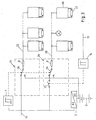
- Fig. 3 such, belonging to the prior art device is briefly outlined.
- the device described therein comprises a final circuit 22 of the emergency lighting, in which the lights are operated in continuous operation, and a second end circuit 23 of the emergency lighting, in which the lights are operated in standby mode.
- luminaires with a ballast 20 and a fluorescent lamp 21 can be used.
- commercial incandescent lamps with the final circuits 22, 23 are connected.
- the device according to the prior art further comprises a voltage monitor 14, which can register voltage drops in the area of the sub-distributor 17 of the general lighting.
- the device comprises a central power supply device 16 for the emergency lighting, via the normal state, d. H. if no voltage drops are registered, the permanently operated lights are constantly supplied with power. These lights may be, for example, lights that characterize escape routes and emergency exits.
- the voltage monitor 14 registers a voltage drop in individual sections of the general lighting, it acts on a switching element 25 arranged in a circuit switching device 24, which connects the ready light lamps in the final circuit 23 to the central power supply device 16. If this also fails, this is registered by another voltage monitor 1.
- This voltage monitor 1 then acts on the switching elements 26 arranged in the circuit switching devices 24, which then connect both end circuits 22, 23 to a central battery 3.
- the problem underlying the present invention is the provision of a device for central emergency lighting of the type mentioned, which can be implemented flexibly and with little installation effort.
- each ready light is exactly one switching unit and each switching unit associated with exactly one ready light.
- the switching unit can be integrated, for example, in the housing of the ready light, so that there is a compact unit.
- each of the lights is associated with a switching element, which is preferably designed as a switch or as a programmable element such as EEPROM, with which it can be selected whether the light is operated as a continuous light or as a ready light.
- each of the lights is associated with a switching unit with means for voltage shape detection, the light can only be switched on or off depending on the voltage shape when it is operated as a standby light due to the corresponding position of the switch.
- luminaires designed as compact units in, for example, a final circuit and subsequently determine as desired whether the luminaire should be operated as a continuous light or as a ready light.
- the switching units switch off the ready light lights when an AC voltage is present in the final circuits. Furthermore, the switching units switch on the ready light lamps advantageously then when a DC voltage is present in the final circuits. For this purpose, therefore, the voltage form when Tinregistrierung a voltage drop must not be changed, because then usually rests the AC voltage of the central power supply device for the emergency power supply to the final circuits. Furthermore, even in case of failure of the central power supply device for the emergency lighting, the voltage form must not be changed, because then the DC voltage of the central battery is applied in the final circuits.
- the means for changing the voltage form are rectifiers, in particular Bridge rectifier, executed. These rectifiers are switched upon registration of a voltage drop in one or more sections of the general lighting of switching elements arranged in the circuit switching devices between the central power supply device and the final circuits and then convert the alternating current from the central power supply into an optionally pulsating direct current. This DC current is then detected by the switching units of the lights, whereupon they turn on the lights when they are operated as ready light lights.
- the device according to the invention may comprise fluorescent lamps, wherein the switching unit may then be integrated in the associated ballast or may be associated with a commercially available ballast as an additional switching module of a fluorescent lamp.
- the device may comprise incandescent lamps, in which case the switching unit of the incandescent lamp is assigned as an additional switching module.
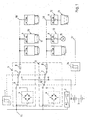
- An illustrated in Fig. 1 embodiment of a device according to the invention for central emergency lighting comprises at least two final circuits 18 of the emergency lighting and at least two, associated with these circuit switching 5.
- a device according to the invention for central emergency lighting more than two final circuits 18, each with a associated circuit switching device 5 includes.
- FIG. 1 for the central emergency lighting supply is shown in unipolar fashion.
- the circuit switching means 5 are the input side of the main distributor 16 of a safety power supply, which is used for the emergency lighting, and a central battery 3, which is loaded by the main distributor 16 via a charger 2 in normal operation. Switch in normal operation the circuit switching means 5 by the main distributor 16 made available AC mains voltage, for example, 220 volts and 50 hertz via power circuit fuses 8 in the final circuits 18 by.
- commercially available fluorescent lamps can be powered by electronic ballasts 10 with control electronics.
- 12 commercially available lights 13 with integrated electronic ballasts and incandescent lamps 15 can be connected via switching modules.
- Both the electronic ballasts 10 with control electronics and the switching modules 12 include switches 9, which allow switching from a switch position continuous light (DL) in a switch position ready light (BL) and vice versa.
- switches 9 which allow switching from a switch position continuous light (DL) in a switch position ready light (BL) and vice versa.
- DL switch position continuous light
- BL switch position ready light
- continuous light lamps of the emergency lighting must be operated continuously both in normal operation and in emergency operation.
- these may be lights that indicate escape routes and emergency exits.
- the ready lights do not need to be put into operation until the system is switched to emergency mode.
- a voltage monitor 14 which monitors the application of voltage to a sub-distributor 17 of the general lighting registers a voltage drop
- the main distributor 16 of the safety power supply voltage applied controls a voltage drop.
- the end circuits 18 of the emergency lighting can continue to be powered by means of a switch described in more detail below from the main distributor 16 of the safety power supply.
- the voltage monitor 1 which controls the voltage applied to the main distribution 16 of the safety power supply, a voltage drop, so that the final circuits 18 of the emergency lighting can only be supplied via also described below switching from the central battery 3 with power .
- the lights functioning as ready lights must be switched on.
- the voltage monitor 14 acts on the changeover contacts 6 of the circuit switching devices 5.
- the changeover contacts 6 then connect the final circuits 18 via arranged in the circuit switching devices 5 bridge rectifier 4 with the main distributor 16 of the safety power supply.
- Fig. 2b the resulting shape of the voltage applied in the final circuits 18 voltage can be seen.
- the apparent from Fig. 2a form of a normal mains AC voltage is rectified by the bridge rectifier 4 so that the negative branches of the sinusoidal voltage are folded upwards, so that no more polarity reversal takes place.
- the voltage monitor 1 registers the breakdown of the voltage at the main distributor 16 of the safety power supply, the voltage monitor 1 acts on the changeover contacts 7 arranged in the circuit switching devices 5, which connect the end circuits 18 of the emergency lighting to the central battery 3.
- the resulting voltage form of a constant DC voltage over time is shown in FIG. 2c.
- the electronic ballasts 10 and the switching modules 12 represent a switching unit, which enables an activation of the lamps 11, 13, 15 connected to them as a function of the shape of the voltage applied in the final circuits 18 voltage. As long as the respective switches 9 are in the position DL, the lamp is selected as a continuous light and is operated continuously regardless of the choice of voltage waveforms shown in FIGS. 2a to 2c. If the corresponding switches 9 are in the position BL, the lamp 11, 13, 15 connected to the ballast 10 or the switching module 12 must be switched on only in emergency mode.
- the electronic ballasts 10 and the switching modules 12 therefore comprise switching elements that do not connect to the associated with them lights 11, 13, 15 when applying an AC voltage.
Landscapes
- Business, Economics & Management (AREA)
- Emergency Management (AREA)
- Engineering & Computer Science (AREA)
- Power Engineering (AREA)
- Circuit Arrangement For Electric Light Sources In General (AREA)
- Non-Portable Lighting Devices Or Systems Thereof (AREA)
- Circuit Arrangements For Discharge Lamps (AREA)
Claims (10)
- Dispositif pour l'alimentation centrale d'un éclairage de sécurité, en particulier dans un bâtiment ou similaires, lequel présente aussi un éclairage général en plus de l'alimentation d'un éclairage de sécurité, comprenant :- au moins deux circuits finaux de courant (18) d'un éclairage de sécurité auxquels sont reliés deux groupes de lampes (11, 13, 15), les lampes (11, 13, 15) du premier groupe étant réalisées comme des lampes à lumière permanente et les lampes (11, 13, 15) du second groupe étant réalisées comme des lampes à lumière d'urgence,- un dispositif (16) pour l'alimentation centrale du courant qui assure l'alimentation de l'éclairage de sécurité,- une batterie centrale (3) qui assure l'alimentation de l'éclairage de sécurité,- des unités de contrôle de tension (1, 14) qui enregistrent une baisse de tension dans les différentes sections (17) de l'éclairage général et/ou dans la zone du dispositif d'alimentation centrale courant (16) qui assure l'alimentation de l'éclairage de sécurité, ainsi que- un dispositif (5) de commutation du circuit de courant raccordé aux circuits finaux de courant (18) et qui, dans un premier état du fonctionnement de secours, en cas d'enregistrement d'une baisse de tension dans une ou plusieurs sections de l'éclairage général, assure l'alimentation en courant des lampes à lumière d'urgence (11, 13, 15) à partir du dispositif (16) d'alimentation centrale en courant de l'éclairage de sécurité, et, dans un deuxième état du fonctionnement de secours, en cas d'enregistrement d'une baisse de tension dans la zone du dispositif (16) d'alimentation centrale en courant de l'éclairage de sécurité, assure l'alimentation en courant des lampes à lumière d'urgence (11, 13, 15) et des lampes d'éclairage permanent (11, 13, 15) à partir de la batterie centrale (3),caractérisé en ce quele dispositif comprend des moyens (4) en vue de modifier la forme de la tension appliqué aux circuits finaux du courant, qui, dans le premier état du fonctionnement de secours, modifient de manière ciblée la forme de la tension appliquée sur les circuits finaux du courant (18) pour ainsi brancher les lampes à lumière d'urgence (11, 13, 15) et des unités électriques (10, 12) sont associées aux lampes à lumière d'urgence individuelles (11, 13, 15), qui comprennent des moyens de reconnaissance de la forme de tension et qui branchent ou débranchent les lampes à lumière d'urgence (11, 13, 15) associées en fonction de la forme de la tension appliquée sur les circuits finaux de courant (18) eten ce que des lampes du premier groupe et des lampes du deuxième groupe sont raccordées aux deux circuits finaux de courant (18).2. Dispositif selon la revendication 1, caractérisé en ce que chaque lampe à lumière d'urgence (11, 13, 15) plus précisément une unité électrique (10, 12) et chaque unité électrique (10, 12) plus précisément une lampe à lumière d'urgence (11, 13, 15) est disposée.3. Dispositif selon l'une des revendications 1 ou 2, caractérisé en ce que, chacune des lampes (11, 13, 15) dispose d'un élément électrique (9), lequel est créé préférablement comme interrupteur (9) ou comme élément programmable, par exemple comme EEPROM, avec la possibilité d'être utilisé, dans le cas de la lampe (11, 13, 15) comme lampe à lumière permanente ou comme lampe à lumière d'urgence.4. Disposition selon la revendication 3, caractérisé en ce que chacune des lampes (11, 13, 15) est associée à une unité électrique (10, 12) avec des moyens pour la reconnaissance de la forme de tension, où la lampe (11, 13, 15) est allumée ou éteinte, seulement de façon dépendante à la forme de tension, lorqu'à cause de la position correspondante de l'élément interrupteur (9) celle-ci est actionnée en tant que lampe à lumière d'urgence.5. Dispositif selon l'une des revendications de 1 à 4, caractérisé en ce que les unités électriques (10, 12) des lampes à lumière d'urgence (11, 13, 15) sont éteintes lorsque dans les circuits finals de courant (18) une tension interchangeable est présente, et en ce que les lampes à lumière d'urgence (11, 13, 15) sont allumées lorsque dans les circuits finals de courant (18) est présent un courant continu.6. Dispositif selon l'une des revendications de 1 à 5, caractérisé en ce que, les moyens (4) pour le changement de la forme de tension dans les dispositifs de commutation du circuit du courant (5) sont disposés.7. Dispositif selon l'une des revendications de 1 à 6, caractérisé en ce que les moyens (4) pour le changement de la forme de tension sont réalisés comme un redresseur, en particulier comme un redresseur en pont, lesquels sont connectées en cas d'enregistrement d'une perte de tension dans une ou plusieurs sections de l'éclairage général d'éléments électriques (6) disposés dans les dispositifs de commutation du circuit du courant (5) entre l'alimentation centrale de courant (16) et les circuits finals de courant (18) et le courant alternatif de l'alimentation centrale du courant (16) se transforme, le cas échéant, en un courant qui circule de façon continue.8. Dispositif selon l'une des revendications de 1 à 7, caractérisé en ce que les lampes comprennent une lampe fluorescente (11), alors que l'unité électrique est intégrée dans le respectif appareil en série (10).9. Dispositif selon l'une des revendications de 1 à 7, caractérisé en ce que les lampes comprennent une lampe fluorescente (13) avec un bloc d'alimentation disponible sur le marché, alors que l'unité électrique est réalisée en tant que module électrique additionnel (12).10. Dispositif selon l'une des revendications de 1 à 7, caractérisé en ce que les lampes comprennent une lampe à incandescence (15), alors que l'unité électrique est réalisée comme module électrique additionnel (12).
Priority Applications (1)
| Application Number | Priority Date | Filing Date | Title |
|---|---|---|---|
| DE29924307U DE29924307U1 (de) | 1998-02-25 | 1999-02-24 | Einrichtung zur zentralen Notlichtversorgung |
Applications Claiming Priority (2)
| Application Number | Priority Date | Filing Date | Title |
|---|---|---|---|
| DE19807844A DE19807844C5 (de) | 1998-02-25 | 1998-02-25 | Einrichtung zur zentralen Notlichtversorgung |
| DE19807844 | 1998-02-25 |
Publications (4)
| Publication Number | Publication Date |
|---|---|
| EP0939476A2 EP0939476A2 (fr) | 1999-09-01 |
| EP0939476A3 EP0939476A3 (fr) | 2000-12-13 |
| EP0939476B1 EP0939476B1 (fr) | 2001-10-04 |
| EP0939476B2 true EP0939476B2 (fr) | 2007-06-20 |
Family
ID=7858822
Family Applications (1)
| Application Number | Title | Priority Date | Filing Date |
|---|---|---|---|
| EP99103538A Expired - Lifetime EP0939476B2 (fr) | 1998-02-25 | 1999-02-24 | Dispositif pour l'alimentation centrale d'un éclairage de sécurité |
Country Status (4)
| Country | Link |
|---|---|
| EP (1) | EP0939476B2 (fr) |
| AT (1) | ATE206565T1 (fr) |
| DE (2) | DE19807844C5 (fr) |
| DK (1) | DK0939476T4 (fr) |
Cited By (5)
| Publication number | Priority date | Publication date | Assignee | Title |
|---|---|---|---|---|
| DE102007062957A1 (de) * | 2007-12-21 | 2009-07-02 | Rp-Technik E.K. | Sicherheitsbezogenes Kommunikationsverfahren auf Energieversorgungsleitungen und ein dazugehöriges Netz |
| DE102009022874A1 (de) | 2009-05-27 | 2010-12-02 | Rp-Technik E.K. | Sicherheitsbeleuchtungsanlage mit spezieller Endstromkreistopologie |
| EP2280493A2 (fr) | 2009-06-18 | 2011-02-02 | RP-Technik e. K. | Procédé de communication relatif à la sécurité sur des lignes d'alimentation en énergie et réseau correspondant |
| AT506780B1 (de) * | 2007-12-21 | 2012-09-15 | Rp Technik E K | Sicherheitsbezogenes kommunikationsverfahren auf energieversorgungsleitungen und ein dazugehöriges netz |
| DE202011051576U1 (de) | 2011-10-07 | 2013-01-09 | Rp-Technik E.K. | Sicherheitsbeleuchtungsanlage mit bedarfsbetriebenen Leuchten |
Families Citing this family (28)
| Publication number | Priority date | Publication date | Assignee | Title |
|---|---|---|---|---|
| EP0978924A3 (fr) * | 1998-07-30 | 2001-06-13 | Dr. Ing. Willing Gmbh | Installation électrique pour l'alimentation de puissance de réseau et de secours des éclairages de sécurité |
| DE20205234U1 (de) * | 2002-04-04 | 2003-08-14 | CEAG Sicherheitstechnik GmbH, 59494 Soest | Leuchte |
| DE10241563B3 (de) * | 2002-09-07 | 2004-02-26 | Dr.-Ing. Willing Gmbh | Duo-Endstromkreis |
| DE10245309B4 (de) * | 2002-09-27 | 2005-01-05 | Dr.-Ing. Willing Gmbh | Schaltungsanordnung für die Notbeleuchtung |
| GB2431299B (en) | 2005-10-13 | 2010-05-12 | Thomas & Betts Corp | Emergency lighting system and luminaire module |
| DE102007030451B4 (de) * | 2007-06-29 | 2013-07-18 | Diehl Ako Stiftung & Co. Kg | Stromversorgungsvorrichtung |
| DE102007040555B4 (de) | 2007-08-28 | 2019-01-31 | Tridonic Gmbh & Co Kg | Verfahren und Schaltung zum Identifizieren der Art einer Spannung, insbesondere der einem Betriebsgerät für Notlichtleuchten zugeführten Betriebsspannung |
| DE102008057976A1 (de) * | 2008-11-19 | 2010-05-20 | Zumtobel Lighting Gmbh | Beleuchtungssystem mit Sicherheitsbeleuchtung |
| FR2946828B1 (fr) * | 2009-06-12 | 2011-10-28 | Automatismes En Electronique Systemes A E E S | Systeme d'eclairage de securite. |
| DE102010053767A1 (de) * | 2010-12-08 | 2012-06-14 | Henning Gmbh | Kabinenbeleuchtungsanlage für eine Aufzugskabine |
| DE102010063992A1 (de) | 2010-12-22 | 2012-06-28 | Tridonic Gmbh & Co. Kg | Auswertung der Versorgungsspannung von Betriebsgeräten für Leuchtmittel |
| EP2520988B1 (fr) * | 2011-05-06 | 2016-11-23 | Schuster Energieversorgungssysteme GmbH & Co.KG | Dispositif de surveillance de systèmes de surveillance de réseaux électriques |
| GB2498371B (en) * | 2012-01-12 | 2016-09-14 | Tridonic Gmbh & Co Kg | Lamp controller |
| DE102012220761A1 (de) * | 2012-11-14 | 2014-05-15 | Bag Engineering Gmbh | Multifunktionales Betriebsgerät zum Versorgen eines Verbrauchers wie einer LED-Einrichtung |
| NL2012930B1 (en) * | 2014-06-02 | 2016-06-09 | Eldolab Holding Bv | Light unit driver system. |
| AT515956B1 (de) | 2014-06-23 | 2020-11-15 | Din Dietmar Nocker Facilitymanagement Gmbh | Notbeleuchtungsanlage für ein Gebäude |
| DE102014112726A1 (de) | 2014-09-04 | 2016-03-10 | Inotec Sicherheitstechnik Gmbh | Einrichtung zur Steuerung und Energieversorgung von Leuchten und/oder Leuchtmitteln einer Notbeleuchtung |
| DE202015101685U1 (de) | 2015-04-02 | 2016-07-05 | Inotec Sicherheitstechnik Gmbh | Stromversorgungsvorrichtung für Sicherheits- oder Notleuchten |
| DE102016104480A1 (de) * | 2016-03-11 | 2017-09-14 | Inotec Sicherheitstechnik Gmbh | Verfahren zum Überwachen von Notleuchten einer Notbeleuchtung und Gerät für eine Notleuchte einer Notbeleuchtung |
| DE102016104479A1 (de) * | 2016-03-11 | 2017-09-14 | Inotec Sicherheitstechnik Gmbh | Gerät für eine Leuchte einer Notbeleuchtung und Leuchte mit einem solchem Gerät |
| DE102016104481B4 (de) * | 2016-03-11 | 2024-02-15 | Inotec Sicherheitstechnik Gmbh | Gerät für eine Notbeleuchtung |
| DE102016104476A1 (de) * | 2016-03-11 | 2017-09-14 | Inotec Sicherheitstechnik Gmbh | Gerät für eine Notbeleuchtung und ein Bussystem zur Gebäudeautomatisierung |
| DE102016207023A1 (de) * | 2016-04-26 | 2017-10-26 | Axel Fischer | Automatisches Erkennen von Leuchtenmodulen eines Notlichtsystems |
| DE102016217903A1 (de) | 2016-09-19 | 2018-03-22 | Fischer Akkumulatorentechnik Gmbh | Automatisiertes Erkennen der Zuordnung von Notleuchten zu Stromkreisen |
| DE102016223281A1 (de) * | 2016-11-24 | 2018-05-24 | Tridonic Gmbh & Co Kg | Vorrichtung und Verfahren zum Betreiben eines Leuchtmittels in einem Notfallmodus |
| EP3651312A1 (fr) | 2018-11-12 | 2020-05-13 | polynom ag | Unité de lumière de secours, installation d'éclairage de secours et élément de lumière de secours |
| EP3843240B2 (fr) | 2019-12-23 | 2026-04-29 | Zumtobel Lighting GmbH | Unité centrale pour fournir des moyens d'éclairage d'urgence sur un bus cc |
| EP4305929B1 (fr) * | 2021-03-09 | 2025-04-09 | Signify Holding B.V. | Agencement auxiliaire pour une lampe à tube à del |
Citations (7)
| Publication number | Priority date | Publication date | Assignee | Title |
|---|---|---|---|---|
| DE2835549A1 (de) † | 1977-08-15 | 1979-03-01 | Medibit A S | Verfahren zur uebertragung von information sowie vorrichtung zur durchfuehrung des verfahrens |
| DE3030411A1 (de) † | 1980-08-12 | 1982-03-18 | Achim Dipl.-Ing. Dr.-Ing. 1000 Berlin Willing | Vorrichtung zur einspeisung in eine notleute |
| DE3424991A1 (de) † | 1984-07-06 | 1986-02-06 | Otto 7750 Konstanz Kreutzer | Elektronisches vorschaltgeraet fuer leuchtstofflampen |
| DE3618790A1 (de) † | 1986-06-04 | 1987-12-10 | Norka Norddeutsche Kunststoff | Verfahren zur ueberpruefung einer vielzahl von notleuchten einer beleuchtungsanlage und pruefsystem zur durchfuehrung des verfahrens |
| DE4136673A1 (de) † | 1991-11-05 | 1993-05-13 | Eugen Ringwald | Lichtschaltersystem fuer elektroinstallationen |
| EP0786850A2 (fr) † | 1996-02-02 | 1997-07-30 | Eugen Ringwald | Méthode pour la commutation sélective et commande des consommateurs dans un circuit de courant alternatif |
| DE19611161A1 (de) † | 1996-03-21 | 1997-09-25 | Aeg Ews Stromversorgungen Soer | Schaltungsanordnung zum programmgesteuerten Überwachen und/oder Steuern einer Sicherheitsbeleuchtungsanlage |
Family Cites Families (3)
| Publication number | Priority date | Publication date | Assignee | Title |
|---|---|---|---|---|
| US3809917A (en) * | 1973-06-27 | 1974-05-07 | R Vore | Emergency auxiliary circuit switch and lighting system |
| DE3112314C2 (de) * | 1981-03-28 | 1985-04-18 | Ceag Licht- Und Stromversorgungstechnik Gmbh, 4770 Soest | Sicherheitsbeleuchtungsanlage |
| DE4134298A1 (de) * | 1991-10-17 | 1993-04-22 | Abb Patent Gmbh | Steuerungs- und ueberwachungseinrichtung fuer eine notleuchte |
-
1998
- 1998-02-25 DE DE19807844A patent/DE19807844C5/de not_active Expired - Lifetime
-
1999
- 1999-02-24 EP EP99103538A patent/EP0939476B2/fr not_active Expired - Lifetime
- 1999-02-24 AT AT99103538T patent/ATE206565T1/de active
- 1999-02-24 DK DK99103538T patent/DK0939476T4/da active
- 1999-02-24 DE DE59900289T patent/DE59900289D1/de not_active Expired - Lifetime
Patent Citations (7)
| Publication number | Priority date | Publication date | Assignee | Title |
|---|---|---|---|---|
| DE2835549A1 (de) † | 1977-08-15 | 1979-03-01 | Medibit A S | Verfahren zur uebertragung von information sowie vorrichtung zur durchfuehrung des verfahrens |
| DE3030411A1 (de) † | 1980-08-12 | 1982-03-18 | Achim Dipl.-Ing. Dr.-Ing. 1000 Berlin Willing | Vorrichtung zur einspeisung in eine notleute |
| DE3424991A1 (de) † | 1984-07-06 | 1986-02-06 | Otto 7750 Konstanz Kreutzer | Elektronisches vorschaltgeraet fuer leuchtstofflampen |
| DE3618790A1 (de) † | 1986-06-04 | 1987-12-10 | Norka Norddeutsche Kunststoff | Verfahren zur ueberpruefung einer vielzahl von notleuchten einer beleuchtungsanlage und pruefsystem zur durchfuehrung des verfahrens |
| DE4136673A1 (de) † | 1991-11-05 | 1993-05-13 | Eugen Ringwald | Lichtschaltersystem fuer elektroinstallationen |
| EP0786850A2 (fr) † | 1996-02-02 | 1997-07-30 | Eugen Ringwald | Méthode pour la commutation sélective et commande des consommateurs dans un circuit de courant alternatif |
| DE19611161A1 (de) † | 1996-03-21 | 1997-09-25 | Aeg Ews Stromversorgungen Soer | Schaltungsanordnung zum programmgesteuerten Überwachen und/oder Steuern einer Sicherheitsbeleuchtungsanlage |
Non-Patent Citations (2)
| Title |
|---|
| MLAR Fassung 1989, Seiten 4 bis 6 † |
| MLAR Fassung 1993, Seiten 94 bis 97 † |
Cited By (6)
| Publication number | Priority date | Publication date | Assignee | Title |
|---|---|---|---|---|
| DE102007062957A1 (de) * | 2007-12-21 | 2009-07-02 | Rp-Technik E.K. | Sicherheitsbezogenes Kommunikationsverfahren auf Energieversorgungsleitungen und ein dazugehöriges Netz |
| AT506780B1 (de) * | 2007-12-21 | 2012-09-15 | Rp Technik E K | Sicherheitsbezogenes kommunikationsverfahren auf energieversorgungsleitungen und ein dazugehöriges netz |
| DE102009022874A1 (de) | 2009-05-27 | 2010-12-02 | Rp-Technik E.K. | Sicherheitsbeleuchtungsanlage mit spezieller Endstromkreistopologie |
| DE102009022874B4 (de) * | 2009-05-27 | 2016-01-07 | Rp-Technik Gmbh | Sicherheitsbeleuchtungsanlage mit spezieller Endstromkreistopologie und endstromkreisbildende Schalteinheiten |
| EP2280493A2 (fr) | 2009-06-18 | 2011-02-02 | RP-Technik e. K. | Procédé de communication relatif à la sécurité sur des lignes d'alimentation en énergie et réseau correspondant |
| DE202011051576U1 (de) | 2011-10-07 | 2013-01-09 | Rp-Technik E.K. | Sicherheitsbeleuchtungsanlage mit bedarfsbetriebenen Leuchten |
Also Published As
| Publication number | Publication date |
|---|---|
| EP0939476B1 (fr) | 2001-10-04 |
| DK0939476T4 (da) | 2007-10-15 |
| EP0939476A3 (fr) | 2000-12-13 |
| DE59900289D1 (de) | 2001-11-08 |
| DE19807844C5 (de) | 2006-08-03 |
| DK0939476T3 (da) | 2002-01-28 |
| DE19807844A1 (de) | 1999-09-02 |
| ATE206565T1 (de) | 2001-10-15 |
| DE19807844C2 (de) | 2001-09-13 |
| EP0939476A2 (fr) | 1999-09-01 |
Similar Documents
| Publication | Publication Date | Title |
|---|---|---|
| EP0939476B2 (fr) | Dispositif pour l'alimentation centrale d'un éclairage de sécurité | |
| DE3689434T2 (de) | Redundantes Stromversorgungssystem. | |
| DE3836644C2 (de) | Unabhängiges Notbeleuchtungs-System mit Selbstdiagnose | |
| EP1182762B1 (fr) | Outil électrique et procédé pour son utilisation | |
| EP2353346B1 (fr) | Système d'éclairage doté d'un éclairage de sécurité | |
| DE102014202426A1 (de) | Verfahren zur Prüfung einer Trennstelle eines Photovoltaik-Wechselrichters und Photovoltaik-Wechselrichter | |
| EP3651313B1 (fr) | Unité de lumière de secours, installation d'éclairage de secours et élément de lumière de secours | |
| DE19834304A1 (de) | Beleuchtungsanlage mit zentraler Notstromversorgung | |
| DE102004012215B4 (de) | Ansteuerung von Leuchtmittel-Betriebsgeräten mit einem zentralen kaskadierten AC/DC-Konverter | |
| EP1271745B1 (fr) | Procédé pour l'exploitation de consommateurs d'électricité et dispositif utilisant un tel procédé | |
| DE4020294A1 (de) | Elektrischer schalter der mit zeitverzoegerung mehrere outputs schaltet | |
| DE3738493A1 (de) | Fehlerortungseinrichtung | |
| DE29924307U1 (de) | Einrichtung zur zentralen Notlichtversorgung | |
| DE19834334A1 (de) | Lampenbetriebsgeräte für die zentrale Notstromversorgung | |
| DE3515962A1 (de) | Anordnung zur signaltechnisch sicheren steuerung und ausfallueberwachung wechselstromgespeister doppelfadenlampen eines lichtsignals, insbesondere vorsignals in eisenbahnsignalanlagen | |
| EP3264863B1 (fr) | Procédé d'alimentation en tension électrique de consommateurs | |
| EP3764746A1 (fr) | Appareil de commande | |
| DE19613831C1 (de) | Anlage zur unterbrechungsfreien Stromversorgung | |
| DE60009222T2 (de) | Regelvorrichtung einer leuchtstofflampe | |
| DE10133289B4 (de) | Teilnehmerleitungsanschlusseinheit und Verfahren zur Fehlererkennung in der Stromversorgung | |
| EP0978924A2 (fr) | Installation électrique pour l'alimentation de puissance de réseau et de secours des éclairages de sécurité | |
| DE102005059612B4 (de) | Straßenbeleuchtungssystem mit Schalteinrichtung und ein- und mehrflammigen Leuchten | |
| EP0404143A1 (fr) | Circuit pour surveiller des charges à courant alternatif dans des installations de chemin de fer | |
| DE4324149C2 (de) | Energiesparende Ansteuerschaltung für Sicherheitshinweisleuchten | |
| DE102019125445A1 (de) | Betriebsgerät |
Legal Events
| Date | Code | Title | Description |
|---|---|---|---|
| PUAI | Public reference made under article 153(3) epc to a published international application that has entered the european phase |
Free format text: ORIGINAL CODE: 0009012 |
|
| AK | Designated contracting states |
Kind code of ref document: A2 Designated state(s): AT CH DE DK GB IT LI NL |
|
| AX | Request for extension of the european patent |
Free format text: AL;LT;LV;MK;RO;SI |
|
| PUAL | Search report despatched |
Free format text: ORIGINAL CODE: 0009013 |
|
| AK | Designated contracting states |
Kind code of ref document: A3 Designated state(s): AT BE CH CY DE DK ES FI FR GB GR IE IT LI LU MC NL PT SE |
|
| AX | Request for extension of the european patent |
Free format text: AL;LT;LV;MK;RO;SI |
|
| RIC1 | Information provided on ipc code assigned before grant |
Free format text: 7H 02J 9/06 A, 7H 02J 9/02 B |
|
| 17P | Request for examination filed |
Effective date: 20001206 |
|
| GRAG | Despatch of communication of intention to grant |
Free format text: ORIGINAL CODE: EPIDOS AGRA |
|
| GRAG | Despatch of communication of intention to grant |
Free format text: ORIGINAL CODE: EPIDOS AGRA |
|
| GRAH | Despatch of communication of intention to grant a patent |
Free format text: ORIGINAL CODE: EPIDOS IGRA |
|
| 17Q | First examination report despatched |
Effective date: 20010423 |
|
| GRAH | Despatch of communication of intention to grant a patent |
Free format text: ORIGINAL CODE: EPIDOS IGRA |
|
| GRAA | (expected) grant |
Free format text: ORIGINAL CODE: 0009210 |
|
| AKX | Designation fees paid |
Free format text: AT CH DE DK GB IT LI NL |
|
| AK | Designated contracting states |
Kind code of ref document: B1 Designated state(s): AT CH DE DK GB IT LI NL |
|
| PG25 | Lapsed in a contracting state [announced via postgrant information from national office to epo] |
Ref country code: IT Free format text: LAPSE BECAUSE OF FAILURE TO SUBMIT A TRANSLATION OF THE DESCRIPTION OR TO PAY THE FEE WITHIN THE PRESCRIBED TIME-LIMIT;WARNING: LAPSES OF ITALIAN PATENTS WITH EFFECTIVE DATE BEFORE 2007 MAY HAVE OCCURRED AT ANY TIME BEFORE 2007. THE CORRECT EFFECTIVE DATE MAY BE DIFFERENT FROM THE ONE RECORDED. Effective date: 20011004 Ref country code: GB Free format text: LAPSE BECAUSE OF FAILURE TO SUBMIT A TRANSLATION OF THE DESCRIPTION OR TO PAY THE FEE WITHIN THE PRESCRIBED TIME-LIMIT Effective date: 20011004 |
|
| REF | Corresponds to: |
Ref document number: 206565 Country of ref document: AT Date of ref document: 20011015 Kind code of ref document: T |
|
| REG | Reference to a national code |
Ref country code: CH Ref legal event code: EP |
|
| REF | Corresponds to: |
Ref document number: 59900289 Country of ref document: DE Date of ref document: 20011108 |
|
| REG | Reference to a national code |
Ref country code: DK Ref legal event code: T3 |
|
| GBV | Gb: ep patent (uk) treated as always having been void in accordance with gb section 77(7)/1977 [no translation filed] |
Effective date: 20011004 |
|
| PLBI | Opposition filed |
Free format text: ORIGINAL CODE: 0009260 |
|
| PLBQ | Unpublished change to opponent data |
Free format text: ORIGINAL CODE: EPIDOS OPPO |
|
| PLBF | Reply of patent proprietor to notice(s) of opposition |
Free format text: ORIGINAL CODE: EPIDOS OBSO |
|
| 26 | Opposition filed |
Opponent name: KAUFEL GMBH & CO. KG, NIFE THOMAS & BETTS Effective date: 20020620 |
|
| NLR1 | Nl: opposition has been filed with the epo |
Opponent name: KAUFEL GMBH & CO. KG, NIFE THOMAS & BETTS |
|
| PLBF | Reply of patent proprietor to notice(s) of opposition |
Free format text: ORIGINAL CODE: EPIDOS OBSO |
|
| APBP | Date of receipt of notice of appeal recorded |
Free format text: ORIGINAL CODE: EPIDOSNNOA2O |
|
| APBQ | Date of receipt of statement of grounds of appeal recorded |
Free format text: ORIGINAL CODE: EPIDOSNNOA3O |
|
| APAA | Appeal reference recorded |
Free format text: ORIGINAL CODE: EPIDOS REFN |
|
| APAH | Appeal reference modified |
Free format text: ORIGINAL CODE: EPIDOSCREFNO |
|
| APBU | Appeal procedure closed |
Free format text: ORIGINAL CODE: EPIDOSNNOA9O |
|
| PUAH | Patent maintained in amended form |
Free format text: ORIGINAL CODE: 0009272 |
|
| STAA | Information on the status of an ep patent application or granted ep patent |
Free format text: STATUS: PATENT MAINTAINED AS AMENDED |
|
| 27A | Patent maintained in amended form |
Effective date: 20070620 |
|
| AK | Designated contracting states |
Kind code of ref document: B2 Designated state(s): AT CH DE DK GB IT LI NL |
|
| REG | Reference to a national code |
Ref country code: CH Ref legal event code: AEN Free format text: AUFRECHTERHALTUNG DES PATENTES IN GEAENDERTER FORM |
|
| NLR2 | Nl: decision of opposition |
Effective date: 20070620 |
|
| REG | Reference to a national code |
Ref country code: DK Ref legal event code: T4 |
|
| NLR3 | Nl: receipt of modified translations in the netherlands language after an opposition procedure | ||
| PGFP | Annual fee paid to national office [announced via postgrant information from national office to epo] |
Ref country code: DK Payment date: 20130218 Year of fee payment: 15 |
|
| PGFP | Annual fee paid to national office [announced via postgrant information from national office to epo] |
Ref country code: NL Payment date: 20130219 Year of fee payment: 15 |
|
| REG | Reference to a national code |
Ref country code: DE Ref legal event code: R097 Ref document number: 59900289 Country of ref document: DE |
|
| REG | Reference to a national code |
Ref country code: DE Ref legal event code: R040 Ref document number: 59900289 Country of ref document: DE Effective date: 20131219 |
|
| REG | Reference to a national code |
Ref country code: NL Ref legal event code: V1 Effective date: 20140901 |
|
| REG | Reference to a national code |
Ref country code: DK Ref legal event code: EBP Effective date: 20140228 |
|
| PG25 | Lapsed in a contracting state [announced via postgrant information from national office to epo] |
Ref country code: NL Free format text: LAPSE BECAUSE OF NON-PAYMENT OF DUE FEES Effective date: 20140901 |
|
| PG25 | Lapsed in a contracting state [announced via postgrant information from national office to epo] |
Ref country code: DK Free format text: LAPSE BECAUSE OF NON-PAYMENT OF DUE FEES Effective date: 20140228 |
|
| PGFP | Annual fee paid to national office [announced via postgrant information from national office to epo] |
Ref country code: CH Payment date: 20150218 Year of fee payment: 17 |
|
| PGFP | Annual fee paid to national office [announced via postgrant information from national office to epo] |
Ref country code: AT Payment date: 20150219 Year of fee payment: 17 |
|
| REG | Reference to a national code |
Ref country code: CH Ref legal event code: PL |
|
| REG | Reference to a national code |
Ref country code: AT Ref legal event code: MM01 Ref document number: 206565 Country of ref document: AT Kind code of ref document: T Effective date: 20160224 |
|
| PG25 | Lapsed in a contracting state [announced via postgrant information from national office to epo] |
Ref country code: CH Free format text: LAPSE BECAUSE OF NON-PAYMENT OF DUE FEES Effective date: 20160229 Ref country code: LI Free format text: LAPSE BECAUSE OF NON-PAYMENT OF DUE FEES Effective date: 20160229 |
|
| PG25 | Lapsed in a contracting state [announced via postgrant information from national office to epo] |
Ref country code: AT Free format text: LAPSE BECAUSE OF NON-PAYMENT OF DUE FEES Effective date: 20160224 |
|
| PGFP | Annual fee paid to national office [announced via postgrant information from national office to epo] |
Ref country code: DE Payment date: 20170228 Year of fee payment: 19 |
|
| REG | Reference to a national code |
Ref country code: DE Ref legal event code: R119 Ref document number: 59900289 Country of ref document: DE |
|
| PG25 | Lapsed in a contracting state [announced via postgrant information from national office to epo] |
Ref country code: DE Free format text: LAPSE BECAUSE OF NON-PAYMENT OF DUE FEES Effective date: 20180901 |