EP0939532B1 - Dispositif d'affichage pour une unité de communication - Google Patents
Dispositif d'affichage pour une unité de communication Download PDFInfo
- Publication number
- EP0939532B1 EP0939532B1 EP99301236A EP99301236A EP0939532B1 EP 0939532 B1 EP0939532 B1 EP 0939532B1 EP 99301236 A EP99301236 A EP 99301236A EP 99301236 A EP99301236 A EP 99301236A EP 0939532 B1 EP0939532 B1 EP 0939532B1
- Authority
- EP
- European Patent Office
- Prior art keywords
- display
- assembly
- protection window
- communication unit
- light
- Prior art date
- Legal status (The legal status is an assumption and is not a legal conclusion. Google has not performed a legal analysis and makes no representation as to the accuracy of the status listed.)
- Expired - Lifetime
Links
- 238000004891 communication Methods 0.000 title claims description 33
- 230000008878 coupling Effects 0.000 claims description 14
- 238000010168 coupling process Methods 0.000 claims description 14
- 238000005859 coupling reaction Methods 0.000 claims description 14
- 239000000428 dust Substances 0.000 claims description 14
- 238000000034 method Methods 0.000 claims description 6
- 239000004033 plastic Substances 0.000 claims description 6
- 229920003023 plastic Polymers 0.000 claims description 6
- 238000004519 manufacturing process Methods 0.000 claims description 4
- 239000000853 adhesive Substances 0.000 claims description 2
- 230000001070 adhesive effect Effects 0.000 claims description 2
- 239000006260 foam Substances 0.000 claims description 2
- KKQWHYGECTYFIA-UHFFFAOYSA-N 2,5-dichlorobiphenyl Chemical compound ClC1=CC=C(Cl)C(C=2C=CC=CC=2)=C1 KKQWHYGECTYFIA-UHFFFAOYSA-N 0.000 description 11
- SXHLTVKPNQVZGL-UHFFFAOYSA-N 1,2-dichloro-3-(3-chlorophenyl)benzene Chemical compound ClC1=CC=CC(C=2C(=C(Cl)C=CC=2)Cl)=C1 SXHLTVKPNQVZGL-UHFFFAOYSA-N 0.000 description 5
- 239000011521 glass Substances 0.000 description 4
- 238000001746 injection moulding Methods 0.000 description 4
- 239000004973 liquid crystal related substance Substances 0.000 description 3
- 229920003229 poly(methyl methacrylate) Polymers 0.000 description 3
- 239000004417 polycarbonate Substances 0.000 description 3
- 229920000515 polycarbonate Polymers 0.000 description 3
- 239000004926 polymethyl methacrylate Substances 0.000 description 3
- 239000004676 acrylonitrile butadiene styrene Substances 0.000 description 2
- 230000001413 cellular effect Effects 0.000 description 2
- 239000000463 material Substances 0.000 description 2
- 239000002184 metal Substances 0.000 description 2
- 239000006096 absorbing agent Substances 0.000 description 1
- XECAHXYUAAWDEL-UHFFFAOYSA-N acrylonitrile butadiene styrene Chemical compound C=CC=C.C=CC#N.C=CC1=CC=CC=C1 XECAHXYUAAWDEL-UHFFFAOYSA-N 0.000 description 1
- 229920000122 acrylonitrile butadiene styrene Polymers 0.000 description 1
- 230000000712 assembly Effects 0.000 description 1
- 238000000429 assembly Methods 0.000 description 1
- 238000007796 conventional method Methods 0.000 description 1
- 238000006073 displacement reaction Methods 0.000 description 1
- 238000002347 injection Methods 0.000 description 1
- 239000007924 injection Substances 0.000 description 1
- 239000011159 matrix material Substances 0.000 description 1
- 239000011806 microball Substances 0.000 description 1
- 238000012986 modification Methods 0.000 description 1
- 230000004048 modification Effects 0.000 description 1
- 230000000717 retained effect Effects 0.000 description 1
- 230000035939 shock Effects 0.000 description 1
- 238000012546 transfer Methods 0.000 description 1
Images


Classifications
-
- H—ELECTRICITY
- H04—ELECTRIC COMMUNICATION TECHNIQUE
- H04M—TELEPHONIC COMMUNICATION
- H04M1/00—Substation equipment, e.g. for use by subscribers
- H04M1/02—Constructional features of telephone sets
- H04M1/0202—Portable telephone sets, e.g. cordless phones, mobile phones or bar type handsets
- H04M1/0206—Portable telephones comprising a plurality of mechanically joined movable body parts, e.g. hinged housings
- H04M1/0208—Portable telephones comprising a plurality of mechanically joined movable body parts, e.g. hinged housings characterized by the relative motions of the body parts
- H04M1/0235—Slidable or telescopic telephones, i.e. with a relative translation movement of the body parts; Telephones using a combination of translation and other relative motions of the body parts
- H04M1/0237—Sliding mechanism with one degree of freedom
-
- H—ELECTRICITY
- H04—ELECTRIC COMMUNICATION TECHNIQUE
- H04M—TELEPHONIC COMMUNICATION
- H04M1/00—Substation equipment, e.g. for use by subscribers
- H04M1/02—Constructional features of telephone sets
- H04M1/0202—Portable telephone sets, e.g. cordless phones, mobile phones or bar type handsets
- H04M1/026—Details of the structure or mounting of specific components
- H04M1/0266—Details of the structure or mounting of specific components for a display module assembly
-
- H—ELECTRICITY
- H04—ELECTRIC COMMUNICATION TECHNIQUE
- H04M—TELEPHONIC COMMUNICATION
- H04M1/00—Substation equipment, e.g. for use by subscribers
- H04M1/02—Constructional features of telephone sets
- H04M1/22—Illumination; Arrangements for improving the visibility of characters on dials
Definitions
- the invention relates to a display assembly for a communication unit, such as a cellular phone.
- the display assembly includes a liquid crystal display (LCD)
- the display screen is backlighted to obtain a good contrast in the display.
- the LCD is connected to the printed circuit board PCB of the unit via a flex print or a connector.
- the liquid crystals are provided on a glass, and the display is therefore quite fragile.
- some phones are formed foldable with the LCD protected in the folded position, and other phones are provided with a separate protection window aligned with and at a distance from the LCD.
- the protection window is fixed to the front cover of the phone prior to the assembling of the phone.
- the front cover may be received and handled as a unit from a sub-supplier.
- a conventional method of assembling display elements at the same time as the rest of the communication unit is disclosed in WO-A-9750014.
- the need of a gasket between the protection window and the display screen to provide protection against dust is also described.
- a method of assembling a display system for a communication unit is disclosed in EP-A-0310889.
- the display system cannot be assembled separately from the front cover.
- a method of assembling a display assembly for a communication unit comprising the steps of sandwiching a display module including a display screen between a protection window and a plate-shaped, light-guiding member for back lighting said display screen whereby a cavity is created between the display screen and the protection window; and locking said sandwich structure together by coupling means characterised by pre-assembling the display assembly whereby it is assembled before the assembly of the communication unit into a self-carrying structure, and utilising the coupling means to lock the sandwich structure into the self-carrying structure.
- a method of manufacturing a communication unit characterised in that the elements of the display assembly for the communication unit are pre-assembled as an individual item before being fed to the assembly line.
- the assembly of the communication unit on the assembly line can be performed in an environment which is less free of dust than the environment in which the display assembly is pre-assembled.
- a display assembly for a communication unit comprising a protection window, a display module including a display screen, and a back lighting means including a plate-shaped, light-guiding member for back lighting said display screen; and coupling means for maintaining said display module sandwiched between said protection window and said back lighting means, whereby a cavity is created between the display screen and the protection window characterised by the coupling means being configured to lock the sandwich structure into a self-carrying structure, the display assembly, comprising said self-carrying structure, being pre-assembled such that it can be handled as a single item upon assembly of the communication unit and being constructed such that the assembly of said communication unit can be executed without disassembly of said self-carrying structure.
- the display assembly when assembled, may be transported under the same conditions as all other pre-assemblies, e.g. buzzers, batteries, microphones, of communication units, such as e.g. hand portable phones.
- pre-assemblies e.g. buzzers, batteries, microphones
- communication units such as e.g. hand portable phones.
- the invention provides a new and improved method according to which a display assembly for a communication unit may be assembled without any problems of dust between the display screen and the protection window.
- the invention also provides a display assembly that is easy to handle during the assembling of the communication unit.
- the invention also provides a display assembly having a robust interface to the rest of the communication unit.
- the light sources for back lighting the display screen are integrated in the assembly.
- a number of light emitting diodes is mounted on a printed circuit board connected to the display module offset from the display screen. Depressions or holes in the plate-shaped, light-guiding member are provided for receiving said diodes at least partially.
- the coupling of light into the light guide is hereby independent of the relative position between the display assembly and the printed circuit board of the communication unit. The complexity of the mechanical interface between these two parts is reduced.
- the protection window is provided with a slight dome shape to increase its strength and to create a cavity between the rear side of the window and the front side of the display screen.
- the resilient properties of the protection window ensure that the display screen will not be crashed in normal handling.
- By providing a resilient dust seal between the protection window and the display unit along the periphery of the display screen it is ensured that the display screen will not be crashed even when subjected to rough handling.
- the cavity inside the assembly will be dustproof.
- the coupling means are provided on the plate-shaped, light-guiding member and the protection window as a number of plastics lugs and tabs for mutual engagement.
- These lugs may be in the form of gripping walls extending substantially perpendicularly to the plane of the display screen along two opposite sides of the light-guiding member.
- the gripping walls are provided with recesses for receiving corresponding tabs of the protection window, unintended disassembling in the stacking direction is avoided. Unintended torsion of the parts is prevented by the reception of the tabs in the recesses.
- the gripping walls will establish a snap connection with the tabs according to the preferred embodiment.
- the snap connection may be temporarily locked by preventing movement of the gripping wall parts facing away from the protection window.
- the rear side of the plate-shaped, light-guiding member is coated with a reflecting layer which prevents light from escaping via the rear side of the assembly.
- the printed circuit board carrying the light emitting diodes is provided along one side of the display screen on the display unit, and, according to the preferred embodiment, said printed circuit board also carries the display driver and a multi-pin connector part for establishing electrical connections with a communication unit in which the assembly is used.
- the plate-shaped, light-guiding member is extended with a carrier part supporting said display driver carrying said printed circuit board.
- This carrier part is provided with aligning means and fastening means for aligning and fastening the assembly in relation to the communication unit in which the assembly is used.
- Fig. 1 is a perspective view of a preferred embodiment of the communication unit according to the invention.
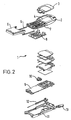
- Fig. 2 is an exploded view of the essential parts of the communication unit shown in fig. 1.
- Fig. 3 is a view of a preferred embodiment of a pre-assembled display assembly according to the invention.
- Fig. 4 is an exploded view of the pre-assembled display assembly shown in fig. 3.
- Fig. 5 is a partially cross-sectional view on an enlarged scale of a part of the pre-assembled display assembly shown in fig. 3.
- the pre-assembled display assembly is integrated into a hard portable phone, e.g. a cellular phone.
- a hard portable phone e.g. a cellular phone.
- a preferred embodiment of this phone is shown in fig. 1.
- the phone is provided with front cover 2 having a window frame 3 encircling the protection window of the display assembly 1.
- the front cover 2 is formed by injection molding in polycarbonate (PC), acrylonitrile butadiene styrene (ABS) or other robust plastics.
- the window frame 3 is formed by injection molding in e.g. ABS and then metalized. It will furthermore be seen how the phone is provided with a slide cover 5 snapped onto a metal slide frame 6 sliding in slide tracks 7 in the front cover 2 along a keypad area and in extension thereof
- the front cover 2 is provided with a plurality of openings, the largest one being an opening 4 in which the protection window 14 of the display assembly 1 is received.
- the front cover 2 is provided with sixteen openings through which the keys of a keypad 8 extend.
- a navigation key assembly 10 extends partly through the front cover 2 between the other keys and the display.
- the keypad 8, the navigation key assembly 10 and the display assembly 1 rest on and are electrically connected to a printed circuit board (PCB) 9 of the phone.
- PCB printed circuit board
- An antenna 13 is mounted in the top comer of a back cover 11 and is connected to the RF circuit on the PCB 9.
- a spring based/latch based slide release mechanism 12 is included along one of the side walls of the back cover 11. One end of the slide release mechanism 12 is fixed to the metal slide frame 6. When the latch mechanism (not shown) is released, the spring of the slide release mechanism forces the slide to open in a soft movement.
- the protection window 14 is injection molded in a clear and mechanically resistant plastics material, such as clear polymethyl methacrylate (PMMA).
- PMMA polymethyl methacrylate
- the protection window 14 covers and protects a display screen, e.g. an LCD display 17, provided on a display module 16.
- a dust seal 15 of punched foam provided with an appropriate adhesive is inserted along the edge of the LCD display 17 between the display module 16 and the window 14.
- the protection window 14 is provided with a slight dome shape to increase its strength and to create a cavity between the window 14 and the LCD display 17.
- the resilient properties of the window 14 will protect the LCD display 17, and the presence of the foamed dust seal 15 (works as a shock absorber) will increase this protection significantly.
- the dust seal 15 effectively maintains a dustless cavity between the window 14 and the display module 17 once the pre-assembling has been performed under dustless conditions.
- the LCD display 17 is provided on a glass plate 21 (support for the display 17) as a liquid crystal structure know per se and having connectors arranged in a matrix configuration.
- the display module 16 comprises a small PCB 20 carrying a multi-pin connector part 22 for connecting the display assembly 1 with a corresponding connector part on the PCB 9.
- the connectors in the connector part 22 as a microball grid array with resilient pins the connectors in the corresponding connector part on the PCB 9 may be metallic pads.
- the small PCB 20 carries some components for an LCD driver circuit (just schematically illustrated) and four light emitting diodes (LED) 23 (shown schematically in fig. 5). These circuits will be trivial to a person skilled in the art.
- the back side of the fragile glass plate 21 is supported by a plate-shaped, light-guiding member 18 provided by injection molding in a clear light-guiding plastics material e.g. PC (polycarbonate) or PMMA.
- the plate-shaped, light-guiding member 18 is extended with a carrier part 24 which supports the PCB 20.
- the carrier part 24 is provided with a channel 25 in which the connector part 22 is received.
- the carrier part 24 rests on the PCB 9, and the length of the channel 25 ensures a well-defined pressure which acts on the connector pins.
- the carrier part 24 is furthermore provided with cavities 26 or holes to receive the LED's 23 on the PCB 20.
- the LED's 23 emit light in the direction of the arrow (fig. 5)
- the light enters the light-guiding member 18 for illuminating or back lighting the display screen 17.
- a reflector 19 is adhered to the back side of the light-guiding member to reduce loss of light.
- the carrier part 24 is provided with tabs 27 interacting with corresponding holes 28 in the PCB 20. This reduces the risk of damage to the connector 22 if the phone is dropped.
- the carrier part 24 On each side of the channel 25 the carrier part 24 is provided with two bushings 29 having substantially the same length as the channel 25.
- the display assembly 1 is placed in a front cover 2 positioned with its face downwards.
- the keypad 8 and the navigation key 10 have already been placed in the front cover 2.
- the PCB 9 is placed on the top of the assembled parts. Screws (not shown) are passed through holes in the PCB 9 and the bushing 29 into screw towers (not shown) in the rear side of the front cover 2.
- the pre-assembled display assembly will be fixed to the front cover 2 and the PCB 9.
- the back cover 11 including the antenna 13 is placed on the PCB 9, and the front cover and the back cover are fixed to each other by means of screws (not shown).
- the coupling means for maintaining the display module 16 sandwiched between the protection window 14 and the light-guiding member 18 of the back lighting means are mainly provided along the edge of the light-guiding member 18.
- the light-guiding member 18 is provided with two wall parts 30 along the two sides in parallel with the longitudinal axis of the phone.
- the wall parts 30 extend in the building direction of the display assembly 1 and are divided by a cut 39.
- One of the wall parts 30 is formed with an eye 31, whereby a resilient lug for a snap connection is provided.
- the height of the wall parts 30 corresponds to the overall thickness of the display assembly 1, whereby the top of the wall parts 30 are aligned with the protection window 14.
- the protection window 14 has tabs 34 fitting into the eyes 31.
- the wall parts 30 provided with eyes 31 and the tabs 34 provide a snap connection based coupling means for locking the sandwich structure together to a self-carrying structure.
- the protection window 14 is provided with two cuts 35 defining a tab 40 which, during the assembling of the display assembly 1, is received and fixed in a recess 36 between two hooks 37. Two stops 38 act as supports for the protection window 14.
- the wall parts 30 extend in downwardly directed wall parts 32 which straddle the PCB 9. Via the wall parts 32 the display assembly rests against the back cover 11. When a force is applied to the protection window 14, the wall parts 30, 32 of the light-guiding member transfer the force directly to the back cover 11 of the phone. This prevents a force acting on the protection window 14 from being transferred to the PCB 9.
Landscapes
- Engineering & Computer Science (AREA)
- Signal Processing (AREA)
- Devices For Indicating Variable Information By Combining Individual Elements (AREA)
- Telephone Set Structure (AREA)
- Liquid Crystal (AREA)
- Casings For Electric Apparatus (AREA)
Claims (16)
- Procédé d'assemblage d'un ensemble d'affichage (1) pour une unité de communication, comprenant les étapes consistant à intercaler un module d'affichage (16) comprenant un écran d'affichage (17) entre une fenêtre de protection (14) et un élément de guidage de lumière (18) en forme de plaque pour rétroéclairer ledit écran d'affichage (17), moyennant quoi une cavité est créée entre l'écran d'affichage et la fenêtre de protection ; et
verrouiller ladite structure en sandwich par des moyens d'accouplement (27, 28, 30 à 40), caractérisé par
le préassemblage de l'ensemble d'affichage, moyennant quoi il est assemblé avant l'assemblage de l'unité de communication en une structure autonome, et
l'utilisation des moyens d'accouplement pour verrouiller la structure en sandwich en une structure autonome. - Procédé selon la revendication 1, dans lequel le verrouillage est réalisé par un accouplement par pression de la structure en sandwich.
- Procédé de fabrication d'une unité de communication comprenant les étapes consistant à :fournir des éléments d'affichage pour un ensemble d'affichage (1), comprenant un écran d'affichage (17), une fenêtre de protection (14) et un élément de guidage de lumière (18), à une ligne d'assemblage ;placer les éléments d'affichage à l'intérieur d'une première partie de recouvrement (11) de l'unité de communication et établir une connexion électrique avec une carte de circuit (9) de l'unité de communication ;placer une deuxième partie de recouvrement (2) de l'unité de communication pour enfermer l'ensemble d'affichage de manière à ce que la fenêtre de protection (14) soit reçue dans une ouverture (4) de l'une desdites parties de recouvrement (2) à travers laquelle l'écran d'affichage (17) est visible, caractérisé en ce queles éléments d'affichage (14, 17, 18) de l'ensemble d'affichage sont préassemblés en tant qu'élément individuel avant d'être fournis à la ligne d'assemblage, et le préassemblage est effectué selon la revendication 1 ou 2.
- Procédé selon la revendication 3, comprenant l'assemblage de l'unité de communication sur la ligne d'assemblage dans un environnement qui est moins exempt de poussière que l'environnement dans lequel l'ensemble d'affichage (1) est préassemblé.
- Ensemble d'affichage pour une unité de communication comprenant :une fenêtre de protection (14) ;un module d'affichage (16) comprenant un écran d'affichage (17) ; etdes moyens de rétroéclairage comprenant un élément de guidage de lumière en forme de plaque pour rétroéclairer ledit écran d'affichage (18) ; etdes moyens d'accouplement (30 à 40) pour maintenir ledit module d'affichage intercalé entre ladite fenêtre de protection et lesdits moyens de rétroéclairage, moyennant quoi une cavité est créée entre l'écran d'affichage et la fenêtre de protection, caractérisé parles moyens d'accouplement (30 à 40) étant configurés pour verrouiller la structure en sandwich en une structure autonome,l'ensemble d'affichage, comprenant ladite structure autonome, étant préassemblé de sorte qu'il puisse être manipulé en tant qu'élément unique lors de l'assemblage de l'unité de communication et étant construit de sorte que l'assemblage de ladite unité de communication puisse être exécuté sans désassembler ladite structure autonome.
- Ensemble d'affichage selon la revendication 5, dans lequel les moyens de rétroéclairage (18) comprennent un certain nombre de diodes électroluminescentes (LED, 23) montées sur une carte de circuit imprimé (20) connectée au module d'affichage, décalée de l'écran d'affichage (17), et des creux ou trous (26) dans l'élément de guidage de lumière en forme de plaque pour recevoir lesdites diodes (23) au moins partiellement.
- Ensemble d'affichage selon la revendication 5 ou 6, dans lequel la fenêtre de protection (14) est pourvue d'une forme bombée pour augmenter la résistance et pour créer une cavité entre la fenêtre de protection et l'écran d' affichage (17).
- Ensemble d'affichage selon l'une quelconque des revendications 5 à 7, dans lequel un joint anti-poussière (15) est prévu entre la fenêtre de protection et l'unité d'affichage le long de la périphérie de l'écran d'affichage.
- Ensemble d'affichage selon la revendication 8, dans lequel le joint anti-poussière (15) est réalisé par une mousse plastique poinçonnée revêtue d'un adhésif.
- Ensemble d'affichage selon l'une quelconque des revendications 5 à 9, dans lequel les moyens d'accouplement (30 à 40) sont prévus sur l'élément de guidage de lumière en forme de plaque et la fenêtre de protection en tant qu'un certain nombre de languettes et de pattes en plastique pour une mise en prise mutuelle (27, 28, 31, 33 à 37, 39, 40).
- Ensemble d'affichage selon la revendication 10, dans lequel l'élément de guidage de lumière (18) en forme de plaque est pourvu de parois de serrage (30, 32) s'étendant sensiblement perpendiculairement au plan de l'écran d'affichage (17) le long de deux côtés opposés de celui-ci, et les parois de serrage sont pourvues d'évidements (39) pour recevoir des pattes correspondantes de la fenêtre de protection.
- Ensemble d'affichage selon la revendication 11, dans lequel les parois de serrage (30, 32) sur l'élément de guidage de lumière (18) en forme de plaque et les pattes (33, 34, 40) sur la fenêtre de protection établissent une connexion par pression lors de l'assemblage de l'ensemble avec l'unité d'affichage intercalée entre ceux-ci.
- Ensemble d'affichage selon la revendication 11 ou 12, dans lequel les parois de serrage (30, 32) s'étendent des deux côtés de l'élément de guidage de lumière (18) en forme de plaque, moyennant quoi la connexion par pression peut être verrouillée temporairement en empêchant un mouvement des parties de la paroi de serrage orientées à l'opposé de la fenêtre de protection.
- Ensemble d'affichage selon l'une quelconque des revendications 5 à 13, dans lequel le côté de l'élément de guidage de lumière (18) en forme de plaque orienté à l'opposé de la fenêtre de protection (14) est pourvu d'une couche réfléchissante (19) qui empêche la lumière de s'échapper par l'intermédiaire du côté de l'ensemble orienté à l'opposé de la fenêtre de protection.
- Ensemble d'affichage selon l'une quelconque des revendications 6 à 14, dans lequel la carte de circuit imprimé (20) supportant les diodes électroluminescentes (23) est prévue le long d'un côté de l'écran d'affichage (17) sur l'unité d'affichage (16), et ladite carte de circuit imprimé (20) supporte également le dispositif de commande d'affichage et une partie de connecteur multibroche (22) pour établir des connexions électriques avec une unité de communication dans laquelle l'ensemble est utilisé.
- Ensemble d'affichage selon la revendication 15, dans lequel l'élément de guidage de lumière (18) en forme de plaque est prolongé par une partie de support (24) supportant ladite carte de circuit imprimé (20) supportant le dispositif de commande d'affichage, et est pourvu de moyens d'alignement et de moyens de fixation (25, 27, 28) pour aligner et fixer l'ensemble en relation avec l'unité de communication dans laquelle l'ensemble est utilisé.
Applications Claiming Priority (2)
| Application Number | Priority Date | Filing Date | Title |
|---|---|---|---|
| GB9804278A GB2334807A (en) | 1998-02-27 | 1998-02-27 | Display assembly |
| GB9804278 | 1998-02-27 |
Publications (3)
| Publication Number | Publication Date |
|---|---|
| EP0939532A2 EP0939532A2 (fr) | 1999-09-01 |
| EP0939532A3 EP0939532A3 (fr) | 2003-01-02 |
| EP0939532B1 true EP0939532B1 (fr) | 2005-04-20 |
Family
ID=10827762
Family Applications (1)
| Application Number | Title | Priority Date | Filing Date |
|---|---|---|---|
| EP99301236A Expired - Lifetime EP0939532B1 (fr) | 1998-02-27 | 1999-02-19 | Dispositif d'affichage pour une unité de communication |
Country Status (5)
| Country | Link |
|---|---|
| US (1) | US20010050988A1 (fr) |
| EP (1) | EP0939532B1 (fr) |
| JP (1) | JPH11288229A (fr) |
| DE (1) | DE69924778T2 (fr) |
| GB (1) | GB2334807A (fr) |
Families Citing this family (13)
| Publication number | Priority date | Publication date | Assignee | Title |
|---|---|---|---|---|
| GB2356760B (en) * | 1999-11-23 | 2004-06-23 | Nokia Mobile Phones Ltd | A radiotelephone handset |
| FI19992510A7 (fi) * | 1999-11-24 | 2001-05-25 | Nokia Corp | Elektroniikkalaite ja menetelmä elektroniikkalaitteessa |
| JP4974405B2 (ja) | 2000-08-31 | 2012-07-11 | ソニー株式会社 | サーバ使用方法、サーバ使用予約管理装置およびプログラム格納媒体 |
| FR2818763A1 (fr) * | 2000-12-26 | 2002-06-28 | Koninkl Philips Electronics Nv | Appareil electronique comportant un dispositif d'affichage formant bouton de commande |
| EP2116816B1 (fr) * | 2002-09-20 | 2013-05-01 | Yazaki Corporation | Module de mouvement et compteur l'utilisant |
| US7130185B2 (en) | 2004-06-02 | 2006-10-31 | Research In Motion Limited | Handheld computing device having drop-resistant LCD display |
| EP1603007B1 (fr) * | 2004-06-02 | 2009-07-29 | Research In Motion Limited | Dispositif de calcul portatif avec affichage à crystaux liquides résistant aux chocs de chute |
| TWI413398B (zh) * | 2005-06-03 | 2013-10-21 | Fih Hong Kong Ltd | 攜帶式電子裝置外殼及製作方法 |
| CN1993027A (zh) * | 2005-12-30 | 2007-07-04 | 深圳富泰宏精密工业有限公司 | 携带式电子装置外壳及制造方法 |
| KR101276822B1 (ko) * | 2006-09-05 | 2013-06-18 | 엘지전자 주식회사 | 세탁 장치용 윈도우의 고정 구조 |
| JP5077052B2 (ja) * | 2008-04-28 | 2012-11-21 | 富士通株式会社 | 携帯端末装置 |
| CN203660594U (zh) * | 2013-12-18 | 2014-06-18 | 深圳市万拓电子技术有限公司 | 移动电源 |
| CN106784444B (zh) * | 2017-01-24 | 2020-05-19 | 捷开通讯(深圳)有限公司 | 智能终端套件、智能终端及其可拆卸式智能后盖 |
Family Cites Families (10)
| Publication number | Priority date | Publication date | Assignee | Title |
|---|---|---|---|---|
| JP2755941B2 (ja) * | 1986-06-30 | 1998-05-25 | 三菱電機株式会社 | 面発光装置 |
| EP0310889A3 (fr) * | 1987-10-09 | 1991-07-03 | Andreas Peiker | Dispositif d'affichage comprenant plusieurs sources de lumière |
| US5002368A (en) * | 1989-05-31 | 1991-03-26 | Poqet Computer Corporation | Liquid crystal display mounting structure |
| JP3243833B2 (ja) * | 1992-05-14 | 2002-01-07 | セイコーエプソン株式会社 | 液晶表示装置 |
| JPH05313165A (ja) * | 1992-05-14 | 1993-11-26 | Seiko Epson Corp | バックライト装置及び液晶表示装置 |
| JP2581022B2 (ja) * | 1994-10-31 | 1997-02-12 | 日本電気株式会社 | 表示部付き電子機器の防塵構造 |
| GB2310103B (en) * | 1996-02-06 | 1999-07-07 | Nokia Mobile Phones Ltd | LCD Support frame |
| US6347218B1 (en) * | 1996-02-28 | 2002-02-12 | Nokia Mobile Phones Limited | Electronic device with housing supplement |
| US5822690A (en) * | 1996-04-12 | 1998-10-13 | Motorola, Inc. | Multi-pole switch assembly providing display cover and virtual pivot action |
| US5748270A (en) * | 1996-06-25 | 1998-05-05 | Ericsson, Inc. | LCD with electroluminescent backlighting |
-
1998
- 1998-02-27 GB GB9804278A patent/GB2334807A/en not_active Withdrawn
-
1999
- 1999-02-19 DE DE69924778T patent/DE69924778T2/de not_active Expired - Lifetime
- 1999-02-19 EP EP99301236A patent/EP0939532B1/fr not_active Expired - Lifetime
- 1999-02-26 JP JP11049727A patent/JPH11288229A/ja not_active Withdrawn
- 1999-02-26 US US09/261,605 patent/US20010050988A1/en not_active Abandoned
Also Published As
| Publication number | Publication date |
|---|---|
| DE69924778T2 (de) | 2005-12-15 |
| GB9804278D0 (en) | 1998-04-22 |
| GB2334807A (en) | 1999-09-01 |
| EP0939532A3 (fr) | 2003-01-02 |
| JPH11288229A (ja) | 1999-10-19 |
| DE69924778D1 (de) | 2005-05-25 |
| US20010050988A1 (en) | 2001-12-13 |
| EP0939532A2 (fr) | 1999-09-01 |
Similar Documents
| Publication | Publication Date | Title |
|---|---|---|
| EP0939532A2 (fr) | Dispositif d'affichage pour une unité de communication | |
| US7391863B2 (en) | Method and system for an interchangeable headset module resistant to moisture infiltration | |
| KR101881000B1 (ko) | 디스플레이 장치의 파손 방지 구조를 구비하는 휴대용 단말기 | |
| CN102791097B (zh) | 具有显示单元的便携装置 | |
| US6594472B1 (en) | Exchangeable radiotelephone covers | |
| US20100091439A1 (en) | Portable Electronic Device | |
| US7249861B2 (en) | Keypad assembly | |
| KR20000058094A (ko) | 액정 모듈 장착 구조체 및 이 액정 모듈 장착 구조체가장착된 이동 단말기 | |
| US12112901B2 (en) | Electronic device | |
| US6796719B2 (en) | Optical fiber connector | |
| US5158483A (en) | Antenna connector and concealed test jack | |
| JPH09283950A (ja) | Lcd表示器取付け構造 | |
| US7149558B2 (en) | Portable terminal device | |
| EP0888036B1 (fr) | Montage d'un LCD avec épaisseur réduite et méthode pour monter | |
| KR19990072478A (ko) | 이동전화기핸드세트의개별구성요소를위한피팅장치와이리하여얻어진핸드세트 | |
| EP1638379B1 (fr) | Structure prévenant la séparation intempestive de connecteurs sur des platines et appareil | |
| EP1434410B1 (fr) | Elément de fixation pour un téléphone et téléphone portable | |
| WO2003081972A1 (fr) | Terminal mobile | |
| CN210670155U (zh) | 一种Wi-Fi模块固定结构及移动终端 | |
| US6108213A (en) | Retainer for electronic apparatus | |
| KR102476589B1 (ko) | 전자 기기의 초음파 센서 조립체 및 이를 포함하는 전자 기기 | |
| CN222749151U (zh) | 显示模组和具有其的显示设备 | |
| CN223486445U (zh) | 电子设备 | |
| CN120895417B (zh) | 按键组装结构、按键组装方法以及电子设备 | |
| CN219329100U (zh) | 显示模组及电子设备 |
Legal Events
| Date | Code | Title | Description |
|---|---|---|---|
| PUAI | Public reference made under article 153(3) epc to a published international application that has entered the european phase |
Free format text: ORIGINAL CODE: 0009012 |
|
| AK | Designated contracting states |
Kind code of ref document: A2 Designated state(s): AT BE CH CY DE DK ES FI FR GB GR IE IT LI LU MC NL PT SE |
|
| AX | Request for extension of the european patent |
Free format text: AL;LT;LV;MK;RO;SI |
|
| RAP1 | Party data changed (applicant data changed or rights of an application transferred) |
Owner name: NOKIA CORPORATION |
|
| PUAL | Search report despatched |
Free format text: ORIGINAL CODE: 0009013 |
|
| AK | Designated contracting states |
Kind code of ref document: A3 Designated state(s): AT BE CH CY DE DK ES FI FR GB GR IE IT LI LU MC NL PT SE |
|
| AX | Request for extension of the european patent |
Free format text: AL;LT;LV;MK;RO;SI |
|
| RIC1 | Information provided on ipc code assigned before grant |
Free format text: 7H 04M 1/02 A, 7H 04M 1/22 B |
|
| 17P | Request for examination filed |
Effective date: 20030702 |
|
| AKX | Designation fees paid |
Designated state(s): DE FR GB IT NL |
|
| 17Q | First examination report despatched |
Effective date: 20030828 |
|
| GRAP | Despatch of communication of intention to grant a patent |
Free format text: ORIGINAL CODE: EPIDOSNIGR1 |
|
| GRAS | Grant fee paid |
Free format text: ORIGINAL CODE: EPIDOSNIGR3 |
|
| GRAA | (expected) grant |
Free format text: ORIGINAL CODE: 0009210 |
|
| AK | Designated contracting states |
Kind code of ref document: B1 Designated state(s): DE FR GB IT NL |
|
| PG25 | Lapsed in a contracting state [announced via postgrant information from national office to epo] |
Ref country code: IT Free format text: LAPSE BECAUSE OF FAILURE TO SUBMIT A TRANSLATION OF THE DESCRIPTION OR TO PAY THE FEE WITHIN THE PRESCRIBED TIME-LIMIT;WARNING: LAPSES OF ITALIAN PATENTS WITH EFFECTIVE DATE BEFORE 2007 MAY HAVE OCCURRED AT ANY TIME BEFORE 2007. THE CORRECT EFFECTIVE DATE MAY BE DIFFERENT FROM THE ONE RECORDED. Effective date: 20050420 |
|
| REG | Reference to a national code |
Ref country code: GB Ref legal event code: FG4D |
|
| REG | Reference to a national code |
Ref country code: IE Ref legal event code: FG4D |
|
| REF | Corresponds to: |
Ref document number: 69924778 Country of ref document: DE Date of ref document: 20050525 Kind code of ref document: P |
|
| ET | Fr: translation filed | ||
| PLBE | No opposition filed within time limit |
Free format text: ORIGINAL CODE: 0009261 |
|
| STAA | Information on the status of an ep patent application or granted ep patent |
Free format text: STATUS: NO OPPOSITION FILED WITHIN TIME LIMIT |
|
| 26N | No opposition filed |
Effective date: 20060123 |
|
| PGFP | Annual fee paid to national office [announced via postgrant information from national office to epo] |
Ref country code: NL Payment date: 20110216 Year of fee payment: 13 Ref country code: FR Payment date: 20110218 Year of fee payment: 13 Ref country code: DE Payment date: 20110216 Year of fee payment: 13 |
|
| PGFP | Annual fee paid to national office [announced via postgrant information from national office to epo] |
Ref country code: GB Payment date: 20110216 Year of fee payment: 13 |
|
| REG | Reference to a national code |
Ref country code: NL Ref legal event code: V1 Effective date: 20120901 |
|
| GBPC | Gb: european patent ceased through non-payment of renewal fee |
Effective date: 20120219 |
|
| REG | Reference to a national code |
Ref country code: FR Ref legal event code: ST Effective date: 20121031 |
|
| REG | Reference to a national code |
Ref country code: DE Ref legal event code: R119 Ref document number: 69924778 Country of ref document: DE Effective date: 20120901 |
|
| PG25 | Lapsed in a contracting state [announced via postgrant information from national office to epo] |
Ref country code: NL Free format text: LAPSE BECAUSE OF NON-PAYMENT OF DUE FEES Effective date: 20120901 Ref country code: FR Free format text: LAPSE BECAUSE OF NON-PAYMENT OF DUE FEES Effective date: 20120229 Ref country code: GB Free format text: LAPSE BECAUSE OF NON-PAYMENT OF DUE FEES Effective date: 20120219 |
|
| PG25 | Lapsed in a contracting state [announced via postgrant information from national office to epo] |
Ref country code: DE Free format text: LAPSE BECAUSE OF NON-PAYMENT OF DUE FEES Effective date: 20120901 |