EP0939976B1 - Einrichtung zur codierung von steckplätzen - Google Patents
Einrichtung zur codierung von steckplätzen Download PDFInfo
- Publication number
- EP0939976B1 EP0939976B1 EP97951792A EP97951792A EP0939976B1 EP 0939976 B1 EP0939976 B1 EP 0939976B1 EP 97951792 A EP97951792 A EP 97951792A EP 97951792 A EP97951792 A EP 97951792A EP 0939976 B1 EP0939976 B1 EP 0939976B1
- Authority
- EP
- European Patent Office
- Prior art keywords
- coding
- module
- slots
- slot
- modules
- Prior art date
- Legal status (The legal status is an assumption and is not a legal conclusion. Google has not performed a legal analysis and makes no representation as to the accuracy of the status listed.)
- Expired - Lifetime
Links
- 230000000712 assembly Effects 0.000 claims 1
- 238000000429 assembly Methods 0.000 claims 1
- 238000003780 insertion Methods 0.000 description 6
- 230000037431 insertion Effects 0.000 description 6
- 238000006243 chemical reaction Methods 0.000 description 2
- 230000009286 beneficial effect Effects 0.000 description 1
- 238000011161 development Methods 0.000 description 1
- 230000018109 developmental process Effects 0.000 description 1
- 238000004519 manufacturing process Methods 0.000 description 1
- 230000000717 retained effect Effects 0.000 description 1
- 230000008054 signal transmission Effects 0.000 description 1
- 238000013024 troubleshooting Methods 0.000 description 1
Images
Classifications
-
- H—ELECTRICITY
- H05—ELECTRIC TECHNIQUES NOT OTHERWISE PROVIDED FOR
- H05K—PRINTED CIRCUITS; CASINGS OR CONSTRUCTIONAL DETAILS OF ELECTRIC APPARATUS; MANUFACTURE OF ASSEMBLAGES OF ELECTRICAL COMPONENTS
- H05K7/00—Constructional details common to different types of electric apparatus
- H05K7/14—Mounting supporting structure in casing or on frame or rack
- H05K7/1438—Back panels or connecting means therefor; Terminals; Coding means to avoid wrong insertion
- H05K7/1452—Mounting of connectors; Switching; Reinforcing of back panels
- H05K7/1455—Coding for prevention of wrong insertion
-
- H—ELECTRICITY
- H01—ELECTRIC ELEMENTS
- H01R—ELECTRICALLY-CONDUCTIVE CONNECTIONS; STRUCTURAL ASSOCIATIONS OF A PLURALITY OF MUTUALLY-INSULATED ELECTRICAL CONNECTING ELEMENTS; COUPLING DEVICES; CURRENT COLLECTORS
- H01R13/00—Details of coupling devices of the kinds covered by groups H01R12/70 or H01R24/00 - H01R33/00
- H01R13/64—Means for preventing incorrect coupling
- H01R13/645—Means for preventing incorrect coupling by exchangeable elements on case or base
Definitions
- the invention relates to a device for coding Slots according to the preamble of claim 1.
- connection device allows one modular design, with one connection point for each actuator / sensor connection is available that the respective connection type accordingly with an electronic module for signal conversion can be provided.
- the connection device functions at the same time as a carrier unit for the electronic Modules and has a variety of similar slots for this on. Supply and signal lines are the electronic Modules each via a connector on Slot supplied. Electronic modules can be used different operating voltages, e.g. B.
- a device for coding is known from US Pat. No. 4,595,250 of slots in a carrier unit for electronic Modules known in which the electronic modules a laterally protruding edge and the slots to the Edges have corresponding insertion slots.
- the slots are rotatable links with radially opposite the axis of rotation offset pin provided Position correspond to openings on an electronic module must, so that this can be inserted into the slot.
- the invention has for its object a device to create coding for slots that prevents is that electronic modules are inserted into slots for which they are not suitable.
- the invention has the advantage that in addition to the carrier unit and electronic modules for coding no additional Parts are needed.
- the coding slide is firmly on attached to the carrier unit and therefore cannot be transported or the commissioning of the device for connection external lines are lost.
- On the electronic Modules are only provided with a recess for coding, which, depending on the module type, are already attached during manufacture is and means no additional effort.
- External lines can easily position the slider be adjusted so that the advantage of free miscibility electronic modules in the slots of the carrier unit is retained even after changes. If only the slider can be adjusted with a tool, are accidental manipulations excluded in dealing with the carrier unit.
- a position of the coding slide is advantageous in the no module can be inserted into the respective slot.
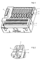
- a carrier unit according to Figure 1 serves as a device for Connection of external lines and is for this on their front provided with two rows of terminals. By Openings 1 are stripped cable ends in terminals inserted through the actuation openings 2 by a Tools are detachable. Via a cable connection 3, the Connection device with a remote control, e.g. B. a personal computer or an automation device that have a suitable communication interface, be coupled.
- a remote control e.g. B. a personal computer or an automation device that have a suitable communication interface
- To convert the signal type to the connected one external lines are electronic modules in Eight slots can be used, which are on the front of the Carrier unit are arranged side by side in the upper part. The right slot is provided with the reference number 4.
- the electronic modules have uniform external dimensions and are therefore interchangeable with each other.
- the electronic modules both the signal lines as well as the lines for their power supply fed.
- the corresponding terminal Before wiring to the individual slots the corresponding terminal is at a slot applied operating voltage has not yet been determined.
- the wiring is the type of module with which a slot is fitted can be, however, predetermined and must be with a Coding slider 5 can be set.
- the coding slide 5 As delivered is the coding slide 5 in a position "0", in no electronic module inserted in the slot can be.
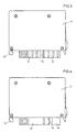
- the coding slide 5 switched to a "DC" or "AC” position, in which is just a module with DC voltage supply 3 or a module with AC voltage supply can be used in accordance with FIG. 4. This prevents that modules with a 24 V DC voltage on slots plugged in, which are wired with 230 V AC voltage are and vice versa.
- Figure 2 shows the coding slide 5 in an enlarged view.
- the coding slide 5 projects into a pin 6 Insertion slot 7 into the spring contacts for contacting housed by contact surfaces of an electronic module are.
- Located on the top of the coding slide 5 a slot 8 into which a screwdriver blade for Changing the slot coding can be used.
- the Dimensions of the coding slide and its surroundings and the forces required for adjustment are such that a change of position without the aid of a tool not possible. This prevents accidental manipulation locked out.
- the invention is based on a Device for connecting external lines as a carrier unit and conversion modules as electronic modules for the slots the carrier unit has been described is the invention also with any other carrier units for coding Slots suitable.
- it can be used for coding the slots of modules in a rack or of slots for front connectors on one with input or output modules equipped programmable logic controller be used.
Landscapes
- Engineering & Computer Science (AREA)
- Microelectronics & Electronic Packaging (AREA)
- Details Of Connecting Devices For Male And Female Coupling (AREA)
- Error Detection And Correction (AREA)
- Reduction Or Emphasis Of Bandwidth Of Signals (AREA)
- Coupling Device And Connection With Printed Circuit (AREA)
- Connector Housings Or Holding Contact Members (AREA)
- Connecting Device With Holders (AREA)
- Table Devices Or Equipment (AREA)
- Connections Arranged To Contact A Plurality Of Conductors (AREA)
- Programmable Controllers (AREA)
Description
- Figur 1
- eine Trägereinheit,
- Figur 2
- einen Ausschnitt aus Figur 1 mit einem Codierschieber in vergrößerter Darstellung,
- Figur 3
- ein elektronisches Modul für Gleichspannungsversorgung und
- Figur 4
- ein elektronisches Modul für eine Versorgung mit Wechselspannung.
Claims (6)
- Einrichtung zur Codierung von Steckplätzen in einer Trägereinheit für elektronische Module, wobei elektronische Module vorgesehen sind, die eine seitlich hervorstehende Kante (9, 10) aufweisen, und wobei die Steckplätze zu den Kanten (9, 10) korrespondierende Einführschlitze (7) aufweisen, dadurch gekennzeichnet, daß an der Trägereinheit für jeden Steckplatz (4) zumindest ein in mehreren Stellungen rastbarer Codierschieber (5) mit einem Zapfen (6) vorgesehen ist, wobei der Zapfen (6) in den jeweiligen Einführschlitz (7) hineinragt, so daß nur diejenigen Module an dem jeweiligen Steckplatz einsteckbar sind, die eine zur jeweiligen Stellung des Codierschiebers (5) korrespondierende Ausnehmung (15, 16) für den Zapfen (6) aufweisen.
- Einrichtung nach Anspruch 1, dadurch gekennzeichnet, daß der Codierschieber (5) nur mit einem Werkzeug verstellbar ist.
- Einrichtung nach Anspruch 1 oder 2, dadurch gekennzeichnet, daß der Codierschieber (5) eine Stellung "0" aufweist, in der kein Modul in den jeweiligen Steckplatz (4) einsteckbar ist.
- Einrichtung nach einem der vorhergehenden Ansprüche, dadurch gekennzeichnet,daß die elektronischen Module als Baugruppen ausgebildet sind,daß die seitlich hervorstehenden Kanten (9, 10) mit Kontaktflächen versehene Leiterplattenkanten (9, 10) sind unddaß die Einführschlitze (7) mit Kontaktfedern versehen sind.
- Trägereinheit für eine Einrichtung nach einem der vorhergehenden Ansprüche, dadurch gekennzeichnet, daß Steckplatze für elektronische Module vorgesehen sind,daß die Steckplätze zu den Kanten (9, 10) der Module korrespondierende Einführschlitze (7) aufweisen,daß an der Trägereinheit für jeden Steckplatz (4) zumindest ein in mehreren Stellungen rastbarer Codierschieber (5) mit einem Zapfen (6) vorgesehen ist, wobei der Zapfen (6) in den jeweiligen Einführschlitz (7) hineinragt, so daß nur diejenigen Module an dem jeweiligen Steckplatz einsteckbar sind, die eine zur jeweiligen Stellung des Codierschiebers (5) korrespondierende Ausnehmung (15, 16) für den Zapfen (6) aufweisen.
- Elektronisches Modul für eine Einrichtung nach einem der Ansprüche 1 bis 4, dadurch gekennzeichnet,daß das elektronische Modul eine seitlich hervorstehende, zu den Einführschlitzen (7) der Steckplätze einer Trägereinheit korrespondierende Kante (9, 10) mit einer Ausnehmung (15, 16) für den Zapfen (6) eines Codierschiebers der Trägereinheit aufweist.
Applications Claiming Priority (3)
| Application Number | Priority Date | Filing Date | Title |
|---|---|---|---|
| DE29620410U | 1996-11-22 | ||
| DE29620410U DE29620410U1 (de) | 1996-11-22 | 1996-11-22 | Einrichtung zur Codierung von Steckplätzen |
| PCT/DE1997/002725 WO1998024153A1 (de) | 1996-11-22 | 1997-11-20 | Einrichtung zur codierung von steckplätzen |
Publications (2)
| Publication Number | Publication Date |
|---|---|
| EP0939976A1 EP0939976A1 (de) | 1999-09-08 |
| EP0939976B1 true EP0939976B1 (de) | 2002-03-20 |
Family
ID=8032372
Family Applications (1)
| Application Number | Title | Priority Date | Filing Date |
|---|---|---|---|
| EP97951792A Expired - Lifetime EP0939976B1 (de) | 1996-11-22 | 1997-11-20 | Einrichtung zur codierung von steckplätzen |
Country Status (10)
| Country | Link |
|---|---|
| US (1) | US6196881B1 (de) |
| EP (1) | EP0939976B1 (de) |
| JP (1) | JP2001505354A (de) |
| KR (1) | KR20000057164A (de) |
| CN (1) | CN1099145C (de) |
| AT (1) | ATE214847T1 (de) |
| DE (2) | DE29620410U1 (de) |
| ES (1) | ES2174324T3 (de) |
| ID (1) | ID22661A (de) |
| WO (1) | WO1998024153A1 (de) |
Cited By (2)
| Publication number | Priority date | Publication date | Assignee | Title |
|---|---|---|---|---|
| DE102004056242A1 (de) * | 2004-11-22 | 2006-05-24 | Abb Patent Gmbh | Modulares Automatisierungssystem |
| DE10330579C5 (de) * | 2002-07-19 | 2016-12-22 | Heidelberger Druckmaschinen Ag | Vorrichtung zum Regeln der Weite des Farbspaltes bei einer Druckmaschine |
Families Citing this family (8)
| Publication number | Priority date | Publication date | Assignee | Title |
|---|---|---|---|---|
| DE10213990B4 (de) * | 2001-08-21 | 2010-01-14 | Phoenix Contact Gmbh & Co. Kg | Elektrische Anschluss- oder Verbindungsklemme |
| DE10301003B3 (de) | 2003-01-13 | 2004-09-30 | Siemens Ag | Modulares Installationsgerät |
| CN102468578B (zh) * | 2010-11-16 | 2016-03-16 | 泰科电子(上海)有限公司 | 电连接器的壳体的防误插接装置的设计方法 |
| DE102013011377A1 (de) * | 2013-07-09 | 2015-01-15 | Abb Technology Ag | Modulare Feldgeräteanschlusseinheit |
| ES2650040T3 (es) | 2014-08-27 | 2018-01-16 | Selectron Systems Ag | Disposición con partes modulares y medios de codificación ajustables |
| EP3331334B1 (de) * | 2016-11-30 | 2021-05-19 | TE Connectivity Germany GmbH | Modulanordnung mit rückstellungsmechanismus |
| DE102018101667B3 (de) * | 2018-01-25 | 2019-04-11 | Lumberg Connect Gmbh | Steckverbinder mit Sekundärsicherung |
| US12414258B2 (en) * | 2023-04-07 | 2025-09-09 | Ciena Corporation | Adjustable shelf/slot keying assemblies and methods for telecommunications and networking equipment |
Family Cites Families (11)
| Publication number | Priority date | Publication date | Assignee | Title |
|---|---|---|---|---|
| CH586962A5 (en) | 1975-08-25 | 1977-04-15 | Siemens Ag Albis | Coding assembly to prevent incorrect block connection - uses identical keys locating in slots in block edges |
| CH607542A5 (en) | 1976-12-16 | 1978-12-29 | Siemens Ag Albis | Printed circuit board mechanical coding system |
| DE2807017C3 (de) * | 1978-02-18 | 1982-01-14 | F. Wieland, Elektrische Industrie GmbH, 8600 Bamberg | Mehrpolige kodierbare Steckverbindung |
| US4307927A (en) * | 1980-03-24 | 1981-12-29 | Rockwell International Corporation | Polarization key for electrical connector |
| FR2544557B1 (fr) | 1983-04-15 | 1986-05-02 | Telemecanique Electrique | Dispositif et procede de codage pour la connexion d'elements dans un automate programmable |
| DE3318137C2 (de) * | 1983-05-18 | 1986-07-31 | Erni Elektroapparate Gmbh, 7321 Adelberg | Mehrpolige elektrische Steckvorrichtung |
| DE3725498A1 (de) * | 1987-07-31 | 1989-02-09 | Siemens Ag | Codiervorrichtung fuer in einen baugruppenrahmen einschiebbare baugruppen |
| DE3830187C3 (de) * | 1988-09-06 | 1995-10-26 | Licentia Gmbh | Kodiervorrichtung für Schaltschrankeinschübe |
| DE4323440A1 (de) * | 1993-05-14 | 1995-02-02 | Siemens Ag | Elektronisches Gerät, insbesondere Automatisierungsgerät |
| US5402320A (en) * | 1993-11-18 | 1995-03-28 | Northern Telecom Limited | Electronic shelf keying and alignment combination |
| DE4420984C2 (de) | 1994-06-10 | 1998-09-17 | Metz Albert Ria Electronic | Kodierbarer Steckverbinder |
-
1996
- 1996-11-22 DE DE29620410U patent/DE29620410U1/de not_active Expired - Lifetime
-
1997
- 1997-11-20 ES ES97951792T patent/ES2174324T3/es not_active Expired - Lifetime
- 1997-11-20 CN CN97199616A patent/CN1099145C/zh not_active Expired - Fee Related
- 1997-11-20 KR KR1019990704453A patent/KR20000057164A/ko not_active Withdrawn
- 1997-11-20 EP EP97951792A patent/EP0939976B1/de not_active Expired - Lifetime
- 1997-11-20 ID IDW990400D patent/ID22661A/id unknown
- 1997-11-20 US US09/308,761 patent/US6196881B1/en not_active Expired - Lifetime
- 1997-11-20 AT AT97951792T patent/ATE214847T1/de not_active IP Right Cessation
- 1997-11-20 WO PCT/DE1997/002725 patent/WO1998024153A1/de not_active Ceased
- 1997-11-20 DE DE59706700T patent/DE59706700D1/de not_active Expired - Lifetime
- 1997-11-20 JP JP52413798A patent/JP2001505354A/ja active Pending
Cited By (3)
| Publication number | Priority date | Publication date | Assignee | Title |
|---|---|---|---|---|
| DE10330579C5 (de) * | 2002-07-19 | 2016-12-22 | Heidelberger Druckmaschinen Ag | Vorrichtung zum Regeln der Weite des Farbspaltes bei einer Druckmaschine |
| DE102004056242A1 (de) * | 2004-11-22 | 2006-05-24 | Abb Patent Gmbh | Modulares Automatisierungssystem |
| DE102004056242B4 (de) | 2004-11-22 | 2021-07-29 | Abb Ag | Modulares Automatisierungsgerät |
Also Published As
| Publication number | Publication date |
|---|---|
| ES2174324T3 (es) | 2002-11-01 |
| DE29620410U1 (de) | 1998-01-02 |
| ATE214847T1 (de) | 2002-04-15 |
| CN1238064A (zh) | 1999-12-08 |
| KR20000057164A (ko) | 2000-09-15 |
| WO1998024153A1 (de) | 1998-06-04 |
| US6196881B1 (en) | 2001-03-06 |
| ID22661A (id) | 1999-12-02 |
| EP0939976A1 (de) | 1999-09-08 |
| CN1099145C (zh) | 2003-01-15 |
| DE59706700D1 (de) | 2002-04-25 |
| JP2001505354A (ja) | 2001-04-17 |
Similar Documents
| Publication | Publication Date | Title |
|---|---|---|
| EP0195955B1 (de) | Rückwandverdrahtung für elektrische Baugruppen | |
| DE60129249T2 (de) | Breadboard für ausbildungszwecke | |
| DE3504712A1 (de) | Elektronischer reglerbaustein und regelvorrichtung in modulbauweise | |
| DE2646616C3 (de) | Anreihbares Einbauteil | |
| EP0584592A1 (de) | Zentraleinheit | |
| WO1998024153A1 (de) | Einrichtung zur codierung von steckplätzen | |
| EP0740082B1 (de) | Modularer elektrischer Teil für einen Ventilblock | |
| EP0540903A1 (de) | Steuerungsbaustein | |
| EP0474082A1 (de) | Codiervorrichtung mit integrierten Sonderkontakten für auf eine Rückwandverdrahtung aufsteckbare elektrische Baugruppen | |
| DE2812332C3 (de) | Vielfachsteckverbindung für Karten mit gedruckter Schaltung | |
| EP0222030A1 (de) | Initiatorklemmenblock | |
| DE102019115177A1 (de) | Modularer Leiterkartensteckverbinder | |
| DE3442056A1 (de) | Steckverbindervorrichtung | |
| DE4032370A1 (de) | Schaltungsanordnung mit wenigstens zwei identischen, integrierten schaltungen oder schaltungsmodulen | |
| DE2907207A1 (de) | Umschaltsteckverbindung | |
| DE2640233B2 (de) | Kabelstecker für eine Vielzahl von Schaltdrähten | |
| AT402459B (de) | Schaltungsanordnung zur aufbereitung von analogen strom- und spannungssignalen | |
| CH607542A5 (en) | Printed circuit board mechanical coding system | |
| DE2808595A1 (de) | Baugruppentraeger fuer elektrische baugruppen | |
| EP0394753B1 (de) | Codiervorrichtung für auf eine Rückwandverdrahtung aufsteckbare elektrische Baugruppen | |
| DE19839708C2 (de) | Niederspannungsversorung | |
| EP0709918A1 (de) | Doppelstöckige, mehrpolige Anschlussstiftleiste | |
| DE3601139A1 (de) | Steckbares relais | |
| EP0940066A2 (de) | Einrichtung zur codierung von steckbaugruppen sowie einrichtung zum anschluss externer leitungen mit einer derartigen codiereinrichtung | |
| DE2948620C2 (de) | Schaltplatte zum Aufbau und zur Demonstration von elektrischen oder elektronischen Schaltungen |
Legal Events
| Date | Code | Title | Description |
|---|---|---|---|
| PUAI | Public reference made under article 153(3) epc to a published international application that has entered the european phase |
Free format text: ORIGINAL CODE: 0009012 |
|
| 17P | Request for examination filed |
Effective date: 19990520 |
|
| AK | Designated contracting states |
Kind code of ref document: A1 Designated state(s): AT CH DE ES FR GB LI |
|
| 17Q | First examination report despatched |
Effective date: 20000228 |
|
| GRAG | Despatch of communication of intention to grant |
Free format text: ORIGINAL CODE: EPIDOS AGRA |
|
| GRAG | Despatch of communication of intention to grant |
Free format text: ORIGINAL CODE: EPIDOS AGRA |
|
| GRAH | Despatch of communication of intention to grant a patent |
Free format text: ORIGINAL CODE: EPIDOS IGRA |
|
| GRAH | Despatch of communication of intention to grant a patent |
Free format text: ORIGINAL CODE: EPIDOS IGRA |
|
| REG | Reference to a national code |
Ref country code: GB Ref legal event code: IF02 |
|
| GRAA | (expected) grant |
Free format text: ORIGINAL CODE: 0009210 |
|
| RIC1 | Information provided on ipc code assigned before grant |
Free format text: 7H 01R 13/645 A, 7H 05K 7/14 B, 7H 01R 12/18 B |
|
| AK | Designated contracting states |
Kind code of ref document: B1 Designated state(s): AT CH DE ES FR GB LI |
|
| REF | Corresponds to: |
Ref document number: 214847 Country of ref document: AT Date of ref document: 20020415 Kind code of ref document: T |
|
| REG | Reference to a national code |
Ref country code: CH Ref legal event code: NV Representative=s name: SIEMENS SCHWEIZ AG Ref country code: CH Ref legal event code: EP |
|
| REF | Corresponds to: |
Ref document number: 59706700 Country of ref document: DE Date of ref document: 20020425 |
|
| ET | Fr: translation filed | ||
| REG | Reference to a national code |
Ref country code: ES Ref legal event code: FG2A Ref document number: 2174324 Country of ref document: ES Kind code of ref document: T3 |
|
| PLBE | No opposition filed within time limit |
Free format text: ORIGINAL CODE: 0009261 |
|
| STAA | Information on the status of an ep patent application or granted ep patent |
Free format text: STATUS: NO OPPOSITION FILED WITHIN TIME LIMIT |
|
| 26N | No opposition filed |
Effective date: 20021223 |
|
| PGFP | Annual fee paid to national office [announced via postgrant information from national office to epo] |
Ref country code: ES Payment date: 20081216 Year of fee payment: 12 Ref country code: AT Payment date: 20081017 Year of fee payment: 12 |
|
| REG | Reference to a national code |
Ref country code: CH Ref legal event code: PCAR Free format text: SIEMENS SCHWEIZ AG;INTELLECTUAL PROPERTY FREILAGERSTRASSE 40;8047 ZUERICH (CH) |
|
| PGFP | Annual fee paid to national office [announced via postgrant information from national office to epo] |
Ref country code: CH Payment date: 20090205 Year of fee payment: 12 |
|
| REG | Reference to a national code |
Ref country code: CH Ref legal event code: PL |
|
| PG25 | Lapsed in a contracting state [announced via postgrant information from national office to epo] |
Ref country code: AT Free format text: LAPSE BECAUSE OF NON-PAYMENT OF DUE FEES Effective date: 20091120 |
|
| PG25 | Lapsed in a contracting state [announced via postgrant information from national office to epo] |
Ref country code: LI Free format text: LAPSE BECAUSE OF NON-PAYMENT OF DUE FEES Effective date: 20091130 Ref country code: CH Free format text: LAPSE BECAUSE OF NON-PAYMENT OF DUE FEES Effective date: 20091130 |
|
| PGFP | Annual fee paid to national office [announced via postgrant information from national office to epo] |
Ref country code: GB Payment date: 20101111 Year of fee payment: 14 |
|
| REG | Reference to a national code |
Ref country code: ES Ref legal event code: FD2A Effective date: 20110408 |
|
| PG25 | Lapsed in a contracting state [announced via postgrant information from national office to epo] |
Ref country code: ES Free format text: LAPSE BECAUSE OF NON-PAYMENT OF DUE FEES Effective date: 20110328 |
|
| PG25 | Lapsed in a contracting state [announced via postgrant information from national office to epo] |
Ref country code: ES Free format text: LAPSE BECAUSE OF NON-PAYMENT OF DUE FEES Effective date: 20091121 |
|
| PGFP | Annual fee paid to national office [announced via postgrant information from national office to epo] |
Ref country code: FR Payment date: 20111201 Year of fee payment: 15 |
|
| PGFP | Annual fee paid to national office [announced via postgrant information from national office to epo] |
Ref country code: DE Payment date: 20120120 Year of fee payment: 15 |
|
| GBPC | Gb: european patent ceased through non-payment of renewal fee |
Effective date: 20121120 |
|
| REG | Reference to a national code |
Ref country code: FR Ref legal event code: ST Effective date: 20130731 |
|
| REG | Reference to a national code |
Ref country code: DE Ref legal event code: R119 Ref document number: 59706700 Country of ref document: DE Effective date: 20130601 |
|
| PG25 | Lapsed in a contracting state [announced via postgrant information from national office to epo] |
Ref country code: DE Free format text: LAPSE BECAUSE OF NON-PAYMENT OF DUE FEES Effective date: 20130601 |
|
| PG25 | Lapsed in a contracting state [announced via postgrant information from national office to epo] |
Ref country code: GB Free format text: LAPSE BECAUSE OF NON-PAYMENT OF DUE FEES Effective date: 20121120 Ref country code: FR Free format text: LAPSE BECAUSE OF NON-PAYMENT OF DUE FEES Effective date: 20121130 |