EP0940040B1 - Dateiprozessor zur verteilung von dezentralen nachrichten - Google Patents
Dateiprozessor zur verteilung von dezentralen nachrichten Download PDFInfo
- Publication number
- EP0940040B1 EP0940040B1 EP97926027A EP97926027A EP0940040B1 EP 0940040 B1 EP0940040 B1 EP 0940040B1 EP 97926027 A EP97926027 A EP 97926027A EP 97926027 A EP97926027 A EP 97926027A EP 0940040 B1 EP0940040 B1 EP 0940040B1
- Authority
- EP
- European Patent Office
- Prior art keywords
- data
- nodes
- node
- data transfer
- file
- Prior art date
- Legal status (The legal status is an assumption and is not a legal conclusion. Google has not performed a legal analysis and makes no representation as to the accuracy of the status listed.)
- Expired - Lifetime
Links
- 238000012546 transfer Methods 0.000 claims abstract description 70
- 230000003287 optical effect Effects 0.000 claims abstract description 6
- 239000000872 buffer Substances 0.000 claims description 35
- 238000013500 data storage Methods 0.000 claims description 33
- 239000011159 matrix material Substances 0.000 claims description 30
- 238000007726 management method Methods 0.000 claims description 12
- 238000004891 communication Methods 0.000 claims description 9
- 230000005540 biological transmission Effects 0.000 claims description 8
- 230000006870 function Effects 0.000 claims description 5
- 238000012384 transportation and delivery Methods 0.000 claims description 2
- 238000000926 separation method Methods 0.000 claims 1
- 238000000034 method Methods 0.000 description 6
- 230000008569 process Effects 0.000 description 5
- 230000008901 benefit Effects 0.000 description 4
- 238000013459 approach Methods 0.000 description 2
- 238000010276 construction Methods 0.000 description 2
- 238000013523 data management Methods 0.000 description 2
- 230000007423 decrease Effects 0.000 description 2
- 238000013467 fragmentation Methods 0.000 description 2
- 238000006062 fragmentation reaction Methods 0.000 description 2
- 230000003362 replicative effect Effects 0.000 description 2
- 230000002459 sustained effect Effects 0.000 description 2
- 230000003466 anti-cipated effect Effects 0.000 description 1
- 230000006399 behavior Effects 0.000 description 1
- 238000007796 conventional method Methods 0.000 description 1
- 238000013461 design Methods 0.000 description 1
- 238000005516 engineering process Methods 0.000 description 1
- 238000000802 evaporation-induced self-assembly Methods 0.000 description 1
- 230000006855 networking Effects 0.000 description 1
- 230000008520 organization Effects 0.000 description 1
- 230000002093 peripheral effect Effects 0.000 description 1
- 238000012545 processing Methods 0.000 description 1
- 230000004044 response Effects 0.000 description 1
- 239000007787 solid Substances 0.000 description 1
Images


Classifications
-
- H—ELECTRICITY
- H04—ELECTRIC COMMUNICATION TECHNIQUE
- H04N—PICTORIAL COMMUNICATION, e.g. TELEVISION
- H04N7/00—Television systems
- H04N7/16—Analogue secrecy systems; Analogue subscription systems
- H04N7/173—Analogue secrecy systems; Analogue subscription systems with two-way working, e.g. subscriber sending a programme selection signal
- H04N7/17309—Transmission or handling of upstream communications
- H04N7/17336—Handling of requests in head-ends
Definitions
- the present invention relates to a file server comprising storage means for storage of information and means for delivering a piece of information to users in response to the user's request.
- Typical server for delivering information comprise several units of RAID disks (RAID, Redundant Array of Inexpensive Disks) each of which being connected through a RAID controller to a common internal bus.
- the bus is of type ISA,EISA,PCI, S-Bus or like.
- Central processor unit CPU and peripheral devices also share the internal bus.
- a user is able to access the server system for retrieving information thereof by connecting via an appropriate interface unit to the bus, for instance via an Ethernet card.
- a limitation on such system for delivering several isochronous data streams is the bus itself because the bus is used both transferring system data between units connected to the bus and information from RAID disks to the users.
- the limitation can be reduced by sharing the bus into two segments which are interconnected by a bridge.
- the system data use its own bus whereas another bus is mainly reserved for transferring stored information to the users.
- FIG. 1 shows a more effective way to deliver information to the users. It depicts a scalable Information such as data files, audio or video files are stored in disk arrayed in several units. Information to be loaded in disks is obtained from service providers via I/O modules. Each module and the commutators stripe incoming data to the controllers of the disk array units and the controllers load data to the disks in accordance with the used RAID system. In the opposite direction information is retrieved from the disk array units and compiled in the I/O unit before transmission to the user.
- I/O modules Each module and the commutators stripe incoming data to the controllers of the disk array units and the controllers load data to the disks in accordance with the used RAID system.
- information is retrieved from the disk array units and compiled in the I/O unit before transmission to the user.
- FIG. 2 depicts another way to build a scalable media server.
- the main storage of information is a content server which is connected to a LAN network.
- a piece of information which is intended to download to a user is copied from the centralized main storage through the LAN to a buffer from which information is further downloaded to the user. Because the transmission rate from the buffer to the user is slower than that of the LAN network, downloading might be started already during copying process. Scalability is obtained by adding new buffers but eventually the bottleneck is the main storage, especially in video-on-demand applications where user behavior can not anticipated.
- FIG. 3 shows still another approach to build a scalable server.
- the idea is to decentralize information to a plurality of servers which are interconnected through the LAN. In case requested information for starting play back is not available in the buffer in question, it is copied from another server. Copying can be carried out before starting play back of information, i.e. before downloading to a user, or downloading could be start during copying process. Scalability is obtained by adding new servers but the bottleneck is the same as that in the server of FIG. 2 and eventually limited transmission capacity of the LAN.
- Drawbacks of the prior art media serves are their limited capability to deliver isochronous information, especially video files. Further, in case several user will simultaneously or in short time intervals have the same video file, its retrieving and loading to user's computer or set top box take a remarkable time.
- the objective of the present invention is to accomplish a server for isochronous data streams which is fully scalable but inexpensive and reasonably easy to manage.
- the server according to the present invention is formed of a plurality of nodes, each node comprising a routing matrix capable to route incoming information like a video clip or like through the node towards the addressed target node, a storage into which the routing matrix is capable to route incoming information addressed to a user connected to this node, wherein a copy of information delivered to the user is stored in the storage.
- a plurality of the nodes in the server can contain same information.
- a control system examines from which node it is most appropriate to transfer the piece of information to the new user's node. While delivering said peace of information to the new user, a copy is made to the storage in the new user's node.
- the nodes of the server are interconnected with links in such a way that the nodes and the links form a hyper cube structure known per se.
- the present invention is based on distributing the user-requested files over the nodes serving at least one user, whereby each node can not serve their own users only but also distribute files over data links to other nodes with a relatively low delay.
- the files requested by several users simultaneously are copied in a chain-reaction-like fashion to all the nodes forming the server.
- the server comprises of a plurality of nodes, in the figure eight nodes are shown.
- the node includes a storage, which is preferably a hard disk, a routing matrix and necessary control electronics. Detailed description of these elements are given later. Further, each node owns a unique address. At least one user line can be connected to every node.
- One or more of the nodes are further connected to a media source. It can be central storage which is connected to the server and which includes media which is offered for users. It can also be a remote source accessible via a transmission network. Media can consist of data files, text files audio and video files etc. How the central storage is constructed and from where it receives data to be stored therein is out of scope of this disclosure.
- the nodes are interconnected via links so that one node is connected with more than one of another nodes.
- the preferred way to logically establish connecting links between nodes will be explained later.
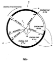
- the basic operating principle of the server entity is as follows:
- user A which is connected to node 8, requests the server to download a file, let's say a video clip.
- the requested file is fetched from central storage 41 or from another source, the entry point to the being node 7.
- Routing matrix 42 in this node routes the requested file through the node toward node 8.
- routing matrix 43 routes the file to storage 44.
- the storage which is preferably a hard disk stores the file. Not until now can the file be downloaded to user A.
- requested video clip as a whole or at least a part of it is firstly stored in the storage of the node and the user connected to the node can obtain information only by reading the content of the storage.
- control system (not shown in the figure) knows that the nearest place where the video clip is retrievable is storage 44 of node A. Due to the fact that all the nodes are interconnected with the links, the control system instructs node 8 to send the video clip to node 3.
- the video clip is first routed via the link A to node 4.
- Routing matrix 45 of that node in turn routes the clip via link B to node 3.
- routing matrix 48 routes the video clip to storage 47, from which the user can download the file. Downloading can begin either after the completed storing process or after the storing process has started and at least a part of the file is stored.
- the video clip is stored in and available from two nodes of the server, namely in node 8 and in node 3.
- the amount of nodes comprising the copy of the video clip increases as the number of the users requesting it increases.
- FIG. 5 shows a structure of the node according to the invention.
- the node has three different functions: it operates as a routing channel between the other nodes, provides means for data transfer from the node to users connected to the node and stores data in its memory for further distribution.
- the node includes at least routing matrix 51, data storage 52 and controller 53.
- the node also includes output connection lines 01, 02,..,On for transferring data from data storage 52 to routing matrix 51 and input connection lines I1, I2,..,In for transferring data from routing matrix 51 to data storage 52.
- node is provided with at least one data connection U1, U2,...,Uk through which data are transmitted to and received from a user.
- Links 8 and 9 which connect the node to other similar nodes or data transfer devices are connected to routing matrix 51.
- the matrix is capable to route data transfers from other nodes or data transfer devices to other nodes or data transfer devices.
- the matrix routes said incoming data to input connection lines I1, I2,..,In, wherein data will be stored in data storage 52. If data which has been stored in the data storage have to transfer to another node of the server, it will be sent through output connection lines O1, O2,..,On to routing matrix 51. Routing matrix connects one of the output connection lines to one or more outgoing channel of link 9. It should be noted that a plurality of data streams can be carried in a single physical line.
- Data storage 53 is formed by a magnetic, optical or solid state memory. With the data storage is associated controller CTRL, serving both data connections for delivering data contained in data storage 52 to at least one immediate user 5 through data connections U1, U2,...,Uk, and at least one input line 7 and at least two outputs, in one or more physical lines 6, connected to routing matrix 51.
- the data storage has sufficient capacity to store the data of at least one continuously playable video and/or audio sequence of an average length.
- Controller 53 is suited for controlling the functions of data storage 52 and routing matrix 51.
- the controller is capable to receive control data from the dedicated users of the node and from the possible central management system through appropriate connection 510.
- the node has the capability to distribute data from its data storage simultaneously both to the dedicated users connected to the node and to at least two other nodes or nodes having access to the data transfer devices. It also has the capability to route data transfer from the inputs to the node to the outputs from the node whenever it does not need access to the contents of the transferred data. Further, the node has the capability to store a file into its data storage whenever the node has an internal need for gaining access to the transferred data. The node is capable to start delivery of a file to other nodes and the users even if the entire content of the file has not yet been copied into the data storage of the node.
- Each buffer has its own connection with the routing matrix to obtain the incoming data and connection to deliver data to the user. Further, a file could be delivered from the ring buffer via the output of the data storage and the routing matrix to at least two outgoing data links from the node with the provision that, at the beginning of said intended file transfer, the start point of the file exists in the ring buffer.
- Each buffer is an elastic ring buffer and it operates as follows:
- ring buffer 61 In the ring buffer there is one write pointer 65, which serves in storing of incoming data 67 into the buffer, and several read pointers 64.
- the maximum number of read pointers is limited by the seek time and data transfer rate of the data storage.
- Read pointers 64 serve the user of the ring buffer and those nodes which are copying files from this node's ring buffer into their own data storage.
- write pointer 65 passes by the starting point of any file, for example file 18, this file is marked and registered by the central management system of the server as no longer available from this ring buffer 61. Slowing down of the write pointer 65 whenever it reaches any of read pointers 64 guarantees undisturbed read for any file.
- the data transfer connection with the routing matrix has the capability to reduce the data write speed so as to prevent the write pointer from passing-by any of the read pointers.
- the server may have a preset minimum data transfer rate or rates defined separately for each different file type whereby the data transmission rate employed between the nodes must exceed the preset minimum data transfer rate or rates.
- the minimum data transfer rate is greater than or equivalent to the maximum real time transfer rate of the particular file type or types.
- all file types can use same rate, whereby the preset data transfer rate(s) must exceed the data transmission rate used between the nodes.
- faster than real time movement of read pointer 64 of the ring buffer assures that the read pointer moves aside faster than required for undisturbed read of any incoming file.
- the maximum real time data rate is related with the situation in which pointers handle several file types.
- the read pointer 04 in FIG. 6 must go before the write pointer 65 with such a rate that the write pointer does not need to slow down its own rate to be slower than the real time rate.
- the elastic ring buffer offers significant advantages. It makes real-time data management easier in the server while simultaneously giving the user a constant amount of storage capacity which is in an uncomplicated manner available to the user. As an additional benefit, data fragmentation in the ring buffer is practically non existent.
- the buffer also makes file management easier: statistically, the life span of a file in the server will be longer if the file is in frequent use over an extended period of time, while files subject to random and rare requests will have only a short life span.
- the central management unit of the server can have any file copied into a storage area outside the ring buffers, either into the data storage of the node, or into a high-capacity magnetic or optical storage of a data transfer node.
- a node is called the data transfer node if it has at least one data transfer device connected thereto, such as a connection to an external memory, to a data communications network, to an information producer or to an essentially real-time, high-capacity data base.
- a node does not have to be provided with user dedicated connections, with the data storage or the routing matrix.
- the best mode to interconnect the nodes with links is to linkage the nodes in such a way that the structure forms a hyper cube, which is known per se.
- the hyper cube architecture known in the art as a typical multinode message-passing server configuration was introduced in the mid-70's. Those who are interested in the theory can obtain more information from W. Millard: Hyperdimensional Microprocessor Collection Seen Functioning as a Mainframe, Digital Design, 1975, Vol. 5, No. 11, p. 20. Later the hypercube has established its position as a widespread parallel-processing architecture.
- a hierarchical network resembling a hypercube is disclosed in US Pat. No. 5,471,580 to which reference is made as a background art only.
- the hyper cube architecture implemented in a media server is novel.
- the invention does not set any limitations on the way how the nodes are interconnected to form a file server.
- the best mode is to use hyper cube architecture.
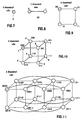
- a file server with a structure of an N-dimensional will be described. Therefore, a short general description of the hyper cube is needed.
- FIG. 7 shows a 0 dimensional hypercube. It has only one node S.
- an 1 dimensional hypercube is formed by copying the original node S and putting data link 20 between these two nodes.
- the original node S is addressed by number 0 and the copy by number 1.
- a 2 dimensional hypercube is formed by copying the template i.e. the 1 dimensional cube and putting links between the respective old and new nodes as shown in FIG. 9.
- the nodes are addressed by adding value 0 in front of the addresses of the template nodes and value 1 in front of the addresses of the copy nodes.
- FIG. 10 shows a 3 dimensional cube which is formed by copying the 2 dimensional cube of FIG.9, putting links between respective nodes and adding addresses.
- FIG. 11 shows a 4 dimensional hyper cube. Forming of that cube from the 3 dimensional hyper cube of fig. 10 should be clear.
- an N-dimensional hypercube can be formed by copying a N-1 dimensional hypercube and connecting the corresponding nodes with data links.
- the copying process of the hypercube in front of the old addresses of the nodes of the template hypercube is added one bit which has value 0 whereas value 1 is added for the addresses of copied hypercube.
- the binary address of two adjacent nodes differs by one bit only.
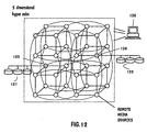
- a server with the hyper cube architecture can be built by making nodes having features described in connection with FIG.5 and connecting the nodes in above described way to form a hyper cube. The result is depicted in FIG. 12.
- high-capacity data bases 121 and 122 are connected to nodes 123 and 122, respectively.
- a central management unit 126 controls operation of the server. The great advantage is that there is no limit to number of the nodes. It is easy to add new nodes and connect them with links to the existent server.
- the server is then fully scalable
- the node according to the present invention is able to transparently route data transfers from a node to another of the server.
- the distance d between two communicating nodes is defined as the smallest number of data links needed for data transfer between these nodes.
- Data communication nodes 123, 124 in FIG. 12 are able to transfer files, e.g., from external servers or from a high-capacity data storage device. There can be several data communication nodes with the same data contents in a single server system.
- the user-requested file may be fetched from the data communication nodes if the file data is not available from any user nodes at a reasonably short distance. If the system detects that none of the data communication nodes contains a minimum amount of file data sufficient for assuring start of sustained data transfer from these external sources, the file must be copied to the data storage of the data communication node prior to passing it to the internal data links of the server.
- the above-described technique represents an exemplifying embodiment of the implementation of a file server. Still higher bit rate can be achieved by clustering several nodes to serve a single user, e.g., by synchronizing the outputs of and combining the data from these nodes into a single bit stream. It should also be noted, that the node according to the invention makes it also possible to implement multiple parallel data connections into the data channels serving as the data transfer links between the nodes using, e.g., any conventional method of modulation, alternation or contention.
- central management system 126 in FIG 13 can be decentralized to the nodes which in such a configuration are arranged to communicate with each other and establish routes without any separate controller. This is possible, because the central management system does not have to contain any information which would not be as readily be available from the nodes.
- hypercube architecture not only gives an easy-to-manage symmetrical structure and the possibility of using identical nodes, but also offers a server availability which does not decrease when the size of the server increases.
- the invention is primarily intended to provide a sustained data transfer to a plurality of simultaneous users.
- the invention is particularly suited for use in video-on-demand systems in which a single server may provide services up to thousands of users.
- an improved fault tolerance of the server is attained, because a server consisting of several nodes may now be inexpensively constructed with the additional advantage that no single-node failure can stop the function of the entire server system.
Landscapes
- Engineering & Computer Science (AREA)
- Multimedia (AREA)
- Signal Processing (AREA)
- Information Retrieval, Db Structures And Fs Structures Therefor (AREA)
- Computer And Data Communications (AREA)
- Information Transfer Between Computers (AREA)
- Two-Way Televisions, Distribution Of Moving Picture Or The Like (AREA)
- Data Exchanges In Wide-Area Networks (AREA)
- Multi Processors (AREA)
Claims (11)
- Dateiserver zur Verteilung von Dateien, insbesondere von Video- und Audiodateien, umfassend einen Satz an ähnlichen Knoten, wobei jeder Knoten mindestens einem Benutzer zugänglich ist und mit anderen Knoten aus dem Knotensatz verbunden ist, und wobei mindestens ein Knoten an andere Datenübertragungskanäle, wie zum Beispiel an ein externes Kommunikationsnetz, an eine nahezu Online-Datenbank, beispielsweise an einen magnetischen oder optischen Massespeicher, oder an Datenübertragungseinrichtungen zur Übertragung von Daten zwischen den Knoten und an eine zentrale Verwaltungseinheit anschließbar ist,
Mittel zur Übermittlung von in dem Server enthaltenen Daten an mindestens einen Benutzer,
durch einen einer Steuerung zugeordneten magnetischen, optischen oder Festkörperspeicher gebildete Datenspeichermittel (2) mit einem Datenanschluss für den mindestens einen Benutzer, der Zugang zum Knoten hat, und außerdem mit mindestens einem Eingang (7) und mindestens zwei Ausgängen (6), die mit einer Routingmatrix (3) verbunden sind, und mit genügend Kapazität, um die Daten einer kontinuierlich abspielbaren Video- und/oder Audiosequenz mittlerer Länge speichern zu können,
die Routingmatrix (3), welche in der Lage ist, die Übertragung von Daten von anderen Knoten oder Datenübertragungseinrichtungen oder von den Datenspeichermitteln (2) des Knoten selbst an andere Knoten oder Datenübertragungseinrichtungen weiterzuleiten oder die Datenübertragung von anderen Knoten und Datenübertragungseinrichtungen an die Datenspeichermittel (2) weiterzuleiten, wobei bei dieser Datenübertragung eine Vielzahl an Datenströmen in einem einzigen physischen Datenübertragungskanal geführt werden können, und
eine Steuereinrichtung (4) zur Steuerung der Funktionen der Datenspeichermittel (2) und der Routingmatrix (3), wobei die Steuereinrichtung (4) in der Lage ist, über eine geeignete Verbindung (10) von den Benutzern des Knoten (1) und von einem zentralen Verwaltungssystem Steuerdaten zu empfangen,
wobei der Knoten weiterhin dafür geeignet ist,
aus seinen Datenspeichermitteln (2) Daten gleichzeitig sowohl an die Benutzer (1) des Knoten als auch an mindestens zwei weitere Knoten oder Datenübertragungseinrichtungen zu verteilen,
Datenübertragungen immer dann von den Eingängen zu den Ausgängen zu routen, wenn kein Zugang zum Inhalt der übertragenen Daten erforderlich ist,
eine Datei immer dann in dem Datenspeicher (2) zu speichern, wenn der Knoten einen internen Bedarf an einem Zugang zu den übertragenen Daten hat, und
mit der Übermittlung einer Datei an weitere Knoten und an die Datenübertragungseinrichtungen und an die Benutzer auch dann zu beginnen, wenn der gesamte Inhalt der Datei noch nicht in den Knoten (2) kopiert wurde. - Dateiserver nach Anspruch 1, dadurch gekennzeichnet, dass die für die Benutzer des Knoten bereitgestellten Datenverbindungen (5) durch die Routingmatrix (3) verlaufen.
- Dateiserver nach Anspruch 1, dadurch gekennzeichnet, dass der Knoten weiterhin umfasst
einen in dem Datenspeichermittel (2) des Knoten für benutzerspezifische elastische Ringpuffer (13) vorgesehenen Speicherraum, wobei jeder elastische Ringpuffer (13) in der Routingmatrix seine eigene Verbindung hat, um eingehende Daten zu erhalten,
eine wahlweise vorgesehene Vielzahl an elastischen Ringpuffern zum Weiterleiten von Benutzeranfragen nach Dateien, die unterschiedliche Datenübertragungsraten benötigen,
eine Anordnung, die es jedem der benutzerspezifischen elastischen Ringpuffer (13) ermöglicht, die auf Anfrage eines Knotenbenutzers von anderen Knoten oder Datenübertragungseinrichtungen abgerufenen Daten zu speichern,
wobei der Knoten in der Lage ist, eine Datei von seinem elastischen Ringpuffer (13) über den Ausgang seines Datenspeichers (7) und über die Routingmatrix (3) an mindestens zwei vom Knoten ausgehenden Datenübertragungskanäle (9) zu übermitteln unter der Bedingung, dass zu Beginn der vorgesehenen Dateiübertragung der Startpunkt der Datei in dem elastischen Ringpuffer (13) vorhanden ist, und dass die Datenübertragungsverbindung zwischen dem elastischen Ringpuffer und der Routingeinrichtung in der Lage ist, die Datenschreibgeschwindigkeit derart zu verringern, dass der Schreibzeiger (15) daran gehindert wird, an den jeweiligen Lesezeigern (14) vorbeizugehen. - Dateiserver nach einem der Ansprüche 1 bis 3, dadurch gekennzeichnet,dass
die Übertragung der Steuerdaten des Knoten in den gleichen ankommenden (8) und ausgehenden (9) Kanälen wie die Dateiübertragung erfolgt,
die eingehenden Steuerdaten mittels einer mit der Routingmatrix (3) verbundenen Steuerdatentrennvorrichtung (11) vom Signal der eingehenden Datenübertragungskanäle getrennt werden, und
die ausgehenden Steuerdaten mittels einer getrennt arbeitenden oder mit der Routingmatrix (3) verbundenen Verbindungsvorrichtung (12) mit den ausgehenden Datenübertragungskanälen verbunden sind. - Dateiserver nach Anspruch 1, dadurch gekennzeichnet, dass der Knoten (1) auch in der Lage ist, Informationen über die Datenübertragungsverbindungen seiner Benutzer zu empfangen.
- Dateiserver nach Anspruch 1, dadurch gekennzeichnet, dass der Knoten mindestens eine mit ihm verbundene Datenübertragungseinrichtung hat, wie zum Beispiel eine Verbindung zu einem externen Speicher, einem Datenkommunikationsnetz (21) oder einem Informationsproduzenten oder einer nahezu Online-Hochleistungsdatenbank.
- Dateiserver nach einem der vorstehenden Ansprüche 1 bis 6, dadurch gekennzeichnet,dass
die Benutzer des Servers die in den Dateien enthaltenen Informationen über die Knoten (1) erhalten,
jeder Knoten (1) mit mindestens drei weiteren Knoten oder Datenübertragungseinrichtungen kommuniziert, und
der Dateiserver eine für die jeweils unterschiedlichen Dateitypen separat definierte Datenübertragungsrate voreingestellt hat, oder alternativ hierzu mit einer Mindestübertragungsrate betrieben wird, die für alle unterschiedlichen Dateitypen hoch genug ist, wobei die zwischen den Knoten (1) verwendete Datenübertragungsrate die voreingestellten oder Mindestübertragungsraten überschreiten muss. - Dateiserver nach Anspruch 7, dadurch gekennzeichnet, dass der Dateiserver mindestens einen Benutzer hat, der in der Lage ist, mit einer Anzahl an Knoten (1) gleichzeitig zu kommunizieren.
- Dateiserver nach Anspruch 7, dadurch gekennzeichnet, dass die Datenübertragung zwischen einem beliebigen Knotenpaar über mehr als eine Route erfolgen kann.
- Dateiserver nach Anspruch 1 oder 6, gekennzeichnet durch die darin eingebauten Datenübertragungseinrichtungen, wobei diese Einrichtungen in der Lage sind, Dateien mit identischem Inhalt über Datenübertragungskanäle (9) zu verteilen und die Fähigkeit aufweisen, Dateien mit identischem Inhalt, die sich dezentralisiert in den getrennten Knoten (1) befinden, derart zu verteilen, dass von den Knoten zu den Datenkommunikationsknoten getrennte Routen erstellt werden können.
- Dateiserver nach Anspruch 7, dadurch gekennzeichnet, dass der Knotensatz in Form eines Hyperkubus angeordnet ist.
Applications Claiming Priority (3)
| Application Number | Priority Date | Filing Date | Title |
|---|---|---|---|
| FI962467 | 1996-06-13 | ||
| FI962467A FI107106B (fi) | 1996-06-13 | 1996-06-13 | Hajautettuun tietoa välittävään rakenteeseen perustuva tiedostopalvelin |
| PCT/FI1997/000366 WO1997048049A2 (en) | 1996-06-13 | 1997-06-11 | File server with a configuration suited for distribution of decentralized data |
Publications (2)
| Publication Number | Publication Date |
|---|---|
| EP0940040A2 EP0940040A2 (de) | 1999-09-08 |
| EP0940040B1 true EP0940040B1 (de) | 2005-04-20 |
Family
ID=8546213
Family Applications (1)
| Application Number | Title | Priority Date | Filing Date |
|---|---|---|---|
| EP97926027A Expired - Lifetime EP0940040B1 (de) | 1996-06-13 | 1997-06-11 | Dateiprozessor zur verteilung von dezentralen nachrichten |
Country Status (5)
| Country | Link |
|---|---|
| EP (1) | EP0940040B1 (de) |
| AT (1) | ATE293867T1 (de) |
| DE (1) | DE69733079T2 (de) |
| FI (1) | FI107106B (de) |
| WO (1) | WO1997048049A2 (de) |
Families Citing this family (7)
| Publication number | Priority date | Publication date | Assignee | Title |
|---|---|---|---|---|
| US6463486B1 (en) * | 1999-04-06 | 2002-10-08 | Microsoft Corporation | System for handling streaming information using a plurality of reader modules by enumerating output pins and associated streams of information |
| US6820144B2 (en) | 1999-04-06 | 2004-11-16 | Microsoft Corporation | Data format for a streaming information appliance |
| US6378035B1 (en) | 1999-04-06 | 2002-04-23 | Microsoft Corporation | Streaming information appliance with buffer read and write synchronization |
| US6535920B1 (en) | 1999-04-06 | 2003-03-18 | Microsoft Corporation | Analyzing, indexing and seeking of streaming information |
| US6748481B1 (en) | 1999-04-06 | 2004-06-08 | Microsoft Corporation | Streaming information appliance with circular buffer for receiving and selectively reading blocks of streaming information |
| FI115082B (fi) * | 1999-12-23 | 2005-02-28 | Valtion Teknillinen | Monisolmuinen palvelin |
| FI116167B (fi) * | 2001-12-18 | 2005-09-30 | Valtion Teknillinen | Arkistoiva tiedostopalvelin |
Family Cites Families (8)
| Publication number | Priority date | Publication date | Assignee | Title |
|---|---|---|---|---|
| US5045940A (en) * | 1989-12-22 | 1991-09-03 | Avid Technology, Inc. | Video/audio transmission systsem and method |
| US5471580A (en) * | 1991-10-01 | 1995-11-28 | Hitachi, Ltd. | Hierarchical network having lower and upper layer networks where gate nodes are selectively chosen in the lower and upper layer networks to form a recursive layer |
| US5371532A (en) * | 1992-05-15 | 1994-12-06 | Bell Communications Research, Inc. | Communications architecture and method for distributing information services |
| CA2127347A1 (en) * | 1993-07-07 | 1995-01-08 | Donald F. Hooper | Segmented video on-demand system |
| US5555244A (en) * | 1994-05-19 | 1996-09-10 | Integrated Network Corporation | Scalable multimedia network |
| CN1122087A (zh) * | 1994-07-21 | 1996-05-08 | 株式会社日立制作所 | 图像信息分配系统 |
| ATE189944T1 (de) * | 1994-09-08 | 2000-03-15 | Ibm | Netzwerkvideoanbietersystem |
| US5940738A (en) * | 1995-05-26 | 1999-08-17 | Hyundai Electronics America, Inc. | Video pedestal network |
-
1996
- 1996-06-13 FI FI962467A patent/FI107106B/fi not_active IP Right Cessation
-
1997
- 1997-06-11 DE DE69733079T patent/DE69733079T2/de not_active Expired - Fee Related
- 1997-06-11 EP EP97926027A patent/EP0940040B1/de not_active Expired - Lifetime
- 1997-06-11 AT AT97926027T patent/ATE293867T1/de not_active IP Right Cessation
- 1997-06-11 WO PCT/FI1997/000366 patent/WO1997048049A2/en not_active Ceased
Also Published As
| Publication number | Publication date |
|---|---|
| DE69733079D1 (de) | 2005-05-25 |
| FI962467A7 (fi) | 1997-12-14 |
| WO1997048049A3 (en) | 1998-01-15 |
| EP0940040A2 (de) | 1999-09-08 |
| DE69733079T2 (de) | 2006-01-19 |
| FI962467A0 (fi) | 1996-06-13 |
| ATE293867T1 (de) | 2005-05-15 |
| WO1997048049A2 (en) | 1997-12-18 |
| FI107106B (fi) | 2001-05-31 |
Similar Documents
| Publication | Publication Date | Title |
|---|---|---|
| US6253271B1 (en) | Bridge for direct data storage device access | |
| US8260949B2 (en) | Method and system for providing multimedia information on demand over wide area networks | |
| CN100431320C (zh) | 大有效负载文件的分段的实时并行交付方法和设备 | |
| EP0845907B1 (de) | System und Methode zur Bearbeitung von Multimedia-Datenströmen in gemeinsamer Ringarchitektur-Multimedia-Subsystemclustern | |
| JP3730686B2 (ja) | データを伝送する方法、データ通信システム、データ通信ネットワーク | |
| US6128467A (en) | Crosspoint switched multimedia system | |
| EP2002640B1 (de) | Transkodierung für ein verteiltes dateisystem | |
| US8645542B2 (en) | Distributed intelligent virtual server | |
| US20020157113A1 (en) | System and method for retrieving and storing multimedia data | |
| FI116167B (fi) | Arkistoiva tiedostopalvelin | |
| US20050160137A1 (en) | Collapsed distrubuted cooperative memory for interactive and scalale media-on-demand systems | |
| WO1998018089A1 (en) | Parallel local area network server | |
| EP0940040B1 (de) | Dateiprozessor zur verteilung von dezentralen nachrichten | |
| US20030074475A1 (en) | Mulitnode server | |
| JPH11146014A (ja) | 分散マルチメディアサーバ装置,分散マルチメディアサーバ情報アクセス方法およびこの方法を実現するプログラムを記録した記録媒体 | |
| US6766393B2 (en) | Method and apparatus for transferring data between independent fiber channel arbitrated loops in an interactive information distribution system | |
| EP0845906A2 (de) | Geteiltes Ring Audio/Videoserversystem | |
| JPH10233991A (ja) | Atmバックボーンネットワークを利用したビデオサーバ | |
| Chen et al. | A fibre channel-based architecture for Internet multimedia server clusters | |
| EP0577362A2 (de) | Erweiterte Architektur für die Speicherung und Verteilung von Bildern | |
| EP0713308B1 (de) | Einrichtung zur Übertragung von Daten | |
| Pegler et al. | Scalability issues for a networked multimedia storage architecture | |
| JPH11298880A (ja) | ストレージ共有型分散ビデオサーバシステム | |
| JP2000148711A (ja) | 動画像サーバシステム | |
| Shim | Supporting I/O-intensive applications in a high performance storage system |
Legal Events
| Date | Code | Title | Description |
|---|---|---|---|
| PUAI | Public reference made under article 153(3) epc to a published international application that has entered the european phase |
Free format text: ORIGINAL CODE: 0009012 |
|
| 17P | Request for examination filed |
Effective date: 19990108 |
|
| AK | Designated contracting states |
Kind code of ref document: A2 Designated state(s): AT BE CH DE DK ES FI FR GB GR IE IT LI LU MC NL PT SE |
|
| 17Q | First examination report despatched |
Effective date: 20030320 |
|
| GRAP | Despatch of communication of intention to grant a patent |
Free format text: ORIGINAL CODE: EPIDOSNIGR1 |
|
| GRAS | Grant fee paid |
Free format text: ORIGINAL CODE: EPIDOSNIGR3 |
|
| GRAA | (expected) grant |
Free format text: ORIGINAL CODE: 0009210 |
|
| RIN1 | Information on inventor provided before grant (corrected) |
Inventor name: OLLIKAINEN, VILLE JUHANA |
|
| AK | Designated contracting states |
Kind code of ref document: B1 Designated state(s): AT BE CH DE DK ES FI FR GB GR IE IT LI LU MC NL PT SE |
|
| PG25 | Lapsed in a contracting state [announced via postgrant information from national office to epo] |
Ref country code: NL Free format text: LAPSE BECAUSE OF FAILURE TO SUBMIT A TRANSLATION OF THE DESCRIPTION OR TO PAY THE FEE WITHIN THE PRESCRIBED TIME-LIMIT Effective date: 20050420 Ref country code: LI Free format text: LAPSE BECAUSE OF FAILURE TO SUBMIT A TRANSLATION OF THE DESCRIPTION OR TO PAY THE FEE WITHIN THE PRESCRIBED TIME-LIMIT Effective date: 20050420 Ref country code: IT Free format text: LAPSE BECAUSE OF FAILURE TO SUBMIT A TRANSLATION OF THE DESCRIPTION OR TO PAY THE FEE WITHIN THE PRE;WARNING: LAPSES OF ITALIAN PATENTS WITH EFFECTIVE DATE BEFORE 2007 MAY HAVE OCCURRED AT ANY TIME BEFORE 2007. THE CORRECT EFFECTIVE DATE MAY BE DIFFERENT FROM THE ONE RECORDED.SCRIBED TIME-LIMIT Effective date: 20050420 Ref country code: FI Free format text: LAPSE BECAUSE OF FAILURE TO SUBMIT A TRANSLATION OF THE DESCRIPTION OR TO PAY THE FEE WITHIN THE PRESCRIBED TIME-LIMIT Effective date: 20050420 Ref country code: CH Free format text: LAPSE BECAUSE OF FAILURE TO SUBMIT A TRANSLATION OF THE DESCRIPTION OR TO PAY THE FEE WITHIN THE PRESCRIBED TIME-LIMIT Effective date: 20050420 Ref country code: BE Free format text: LAPSE BECAUSE OF FAILURE TO SUBMIT A TRANSLATION OF THE DESCRIPTION OR TO PAY THE FEE WITHIN THE PRESCRIBED TIME-LIMIT Effective date: 20050420 Ref country code: AT Free format text: LAPSE BECAUSE OF FAILURE TO SUBMIT A TRANSLATION OF THE DESCRIPTION OR TO PAY THE FEE WITHIN THE PRESCRIBED TIME-LIMIT Effective date: 20050420 |
|
| REG | Reference to a national code |
Ref country code: GB Ref legal event code: FG4D |
|
| REG | Reference to a national code |
Ref country code: CH Ref legal event code: EP |
|
| REG | Reference to a national code |
Ref country code: IE Ref legal event code: FG4D |
|
| REF | Corresponds to: |
Ref document number: 69733079 Country of ref document: DE Date of ref document: 20050525 Kind code of ref document: P |
|
| PG25 | Lapsed in a contracting state [announced via postgrant information from national office to epo] |
Ref country code: LU Free format text: LAPSE BECAUSE OF NON-PAYMENT OF DUE FEES Effective date: 20050611 |
|
| PG25 | Lapsed in a contracting state [announced via postgrant information from national office to epo] |
Ref country code: IE Free format text: LAPSE BECAUSE OF NON-PAYMENT OF DUE FEES Effective date: 20050613 |
|
| PG25 | Lapsed in a contracting state [announced via postgrant information from national office to epo] |
Ref country code: MC Free format text: LAPSE BECAUSE OF NON-PAYMENT OF DUE FEES Effective date: 20050630 |
|
| PG25 | Lapsed in a contracting state [announced via postgrant information from national office to epo] |
Ref country code: SE Free format text: LAPSE BECAUSE OF FAILURE TO SUBMIT A TRANSLATION OF THE DESCRIPTION OR TO PAY THE FEE WITHIN THE PRESCRIBED TIME-LIMIT Effective date: 20050720 Ref country code: GR Free format text: LAPSE BECAUSE OF FAILURE TO SUBMIT A TRANSLATION OF THE DESCRIPTION OR TO PAY THE FEE WITHIN THE PRESCRIBED TIME-LIMIT Effective date: 20050720 Ref country code: DK Free format text: LAPSE BECAUSE OF FAILURE TO SUBMIT A TRANSLATION OF THE DESCRIPTION OR TO PAY THE FEE WITHIN THE PRESCRIBED TIME-LIMIT Effective date: 20050720 |
|
| PG25 | Lapsed in a contracting state [announced via postgrant information from national office to epo] |
Ref country code: ES Free format text: LAPSE BECAUSE OF FAILURE TO SUBMIT A TRANSLATION OF THE DESCRIPTION OR TO PAY THE FEE WITHIN THE PRESCRIBED TIME-LIMIT Effective date: 20050731 |
|
| PG25 | Lapsed in a contracting state [announced via postgrant information from national office to epo] |
Ref country code: PT Free format text: LAPSE BECAUSE OF FAILURE TO SUBMIT A TRANSLATION OF THE DESCRIPTION OR TO PAY THE FEE WITHIN THE PRESCRIBED TIME-LIMIT Effective date: 20050920 |
|
| REG | Reference to a national code |
Ref country code: CH Ref legal event code: PL |
|
| NLV1 | Nl: lapsed or annulled due to failure to fulfill the requirements of art. 29p and 29m of the patents act | ||
| PLBE | No opposition filed within time limit |
Free format text: ORIGINAL CODE: 0009261 |
|
| STAA | Information on the status of an ep patent application or granted ep patent |
Free format text: STATUS: NO OPPOSITION FILED WITHIN TIME LIMIT |
|
| REG | Reference to a national code |
Ref country code: IE Ref legal event code: MM4A |
|
| ET | Fr: translation filed | ||
| 26N | No opposition filed |
Effective date: 20060123 |
|
| PGFP | Annual fee paid to national office [announced via postgrant information from national office to epo] |
Ref country code: DE Payment date: 20080829 Year of fee payment: 12 |
|
| PGFP | Annual fee paid to national office [announced via postgrant information from national office to epo] |
Ref country code: FR Payment date: 20080616 Year of fee payment: 12 |
|
| PGFP | Annual fee paid to national office [announced via postgrant information from national office to epo] |
Ref country code: GB Payment date: 20080620 Year of fee payment: 12 |
|
| GBPC | Gb: european patent ceased through non-payment of renewal fee |
Effective date: 20090611 |
|
| REG | Reference to a national code |
Ref country code: FR Ref legal event code: ST Effective date: 20100226 |
|
| PG25 | Lapsed in a contracting state [announced via postgrant information from national office to epo] |
Ref country code: FR Free format text: LAPSE BECAUSE OF NON-PAYMENT OF DUE FEES Effective date: 20090630 |
|
| PG25 | Lapsed in a contracting state [announced via postgrant information from national office to epo] |
Ref country code: GB Free format text: LAPSE BECAUSE OF NON-PAYMENT OF DUE FEES Effective date: 20090611 |
|
| PG25 | Lapsed in a contracting state [announced via postgrant information from national office to epo] |
Ref country code: DE Free format text: LAPSE BECAUSE OF NON-PAYMENT OF DUE FEES Effective date: 20100101 |