EP0940073A1 - Behälter für Pflanzen und dergleichen - Google Patents
Behälter für Pflanzen und dergleichen Download PDFInfo
- Publication number
- EP0940073A1 EP0940073A1 EP99200657A EP99200657A EP0940073A1 EP 0940073 A1 EP0940073 A1 EP 0940073A1 EP 99200657 A EP99200657 A EP 99200657A EP 99200657 A EP99200657 A EP 99200657A EP 0940073 A1 EP0940073 A1 EP 0940073A1
- Authority
- EP
- European Patent Office
- Prior art keywords
- holder
- dish
- base
- holder according
- circumferential wall
- Prior art date
- Legal status (The legal status is an assumption and is not a legal conclusion. Google has not performed a legal analysis and makes no representation as to the accuracy of the status listed.)
- Withdrawn
Links
- 238000004891 communication Methods 0.000 claims abstract description 9
- 239000012530 fluid Substances 0.000 claims abstract description 7
- 239000002689 soil Substances 0.000 claims description 11
- 239000001963 growth medium Substances 0.000 claims description 10
- 238000001746 injection moulding Methods 0.000 claims description 4
- XLYOFNOQVPJJNP-UHFFFAOYSA-N water Substances O XLYOFNOQVPJJNP-UHFFFAOYSA-N 0.000 description 37
- 241000196324 Embryophyta Species 0.000 description 20
- 230000008901 benefit Effects 0.000 description 9
- 238000004519 manufacturing process Methods 0.000 description 4
- 101100298225 Caenorhabditis elegans pot-2 gene Proteins 0.000 description 3
- 238000000034 method Methods 0.000 description 3
- 238000001816 cooling Methods 0.000 description 2
- 239000007788 liquid Substances 0.000 description 2
- 235000015097 nutrients Nutrition 0.000 description 2
- 230000009286 beneficial effect Effects 0.000 description 1
- 238000006073 displacement reaction Methods 0.000 description 1
- 230000000694 effects Effects 0.000 description 1
- 230000002538 fungal effect Effects 0.000 description 1
- 239000000463 material Substances 0.000 description 1
- 238000005192 partition Methods 0.000 description 1
- 230000008092 positive effect Effects 0.000 description 1
- 238000009423 ventilation Methods 0.000 description 1
- 238000009736 wetting Methods 0.000 description 1
Images

Classifications
-
- A—HUMAN NECESSITIES
- A01—AGRICULTURE; FORESTRY; ANIMAL HUSBANDRY; HUNTING; TRAPPING; FISHING
- A01G—HORTICULTURE; CULTIVATION OF VEGETABLES, FLOWERS, RICE, FRUIT, VINES, HOPS OR SEAWEED; FORESTRY; WATERING
- A01G9/00—Cultivation in receptacles, forcing-frames or greenhouses; Edging for beds, lawn or the like
- A01G9/02—Receptacles, e.g. flower-pots or boxes; Glasses for cultivating flowers
- A01G9/021—Pots formed in one piece; Materials used therefor
Definitions
- the invention relates to a holder according to the preamble of Claim 1.
- a holder of this type is known from French Patent 2,716,070.
- Holders of the type described above are used, for example, to grow pot plants.
- the holders are placed on a floor or the like, for example an ebb and flood base, to which water, optionally containing nutrients and the like, is periodically supplied.
- the water level is raised to above the top side of the circumferential wall of the dishes, so that the dishes fill up, after which the water is removed from the floor.
- the pot plants can then make use of the water which is situated on the dishes.
- a watering can, for example, will be used to introduce water into the dishes.
- a drawback of these known holders is that water will remain standing on the dish up to the level of the top edge of the dish, and consequently the same or even a slightly higher water level will be maintained inside the circumferential wall. This means that the bottom ends of the roots of the plant in question will reach almost continuously into the water, something which must be prevented in particular for the sake of the health of the plant in question. Moreover, this makes it considerably more difficult to refresh the water.
- the object of the invention is to provide a holder of the type described above in which these drawbacks are avoided, while retaining the advantages of this holder.
- a holder according to the invention is characterized by the measures according to Claim 1.
- the at least one elevated section of the base of the holder will support at least part of, and preferably all of, the volume of soil or similar growth medium in the pot at a level which lies virtually at the level of the top edge of the dish.
- this will not reach the soil in the container, or at least will reach it only to a very slight extent, even when the dish is completely full. This means that it is easy to prevent roots of the plant always being able to reach into the water.
- Sufficient water can be taken up into the soil by the suction of the soil when the water level is raised to well above the top edge of the dish, possibly together with displacement of water as a result, for example, of communicating vessels, liquid stresses, adhesion, cohesion and the like.
- the elevated section may be designed in such a manner that a very small fraction of the soil reaches into the water at least when the dish is completely full, but when the dish is partly empty all the soil will extend above the level of the liquid. This ensures a very successful soil hydrology inside the holder, while holders according to the invention, in contrast to known holders, are particularly suitable for use on ebb and flood bases and for intermediate users and end users.
- the base and the raised rim of the dish provide a watertight 'basin'.
- a quantity of water will remain behind in the volume delimited by the raised rim of the dish and the base. This quantity is determined by the level of the free end of the raised rim.
- This quantity of water can be used for further growth of the plant and, as indicated above, the design according to the invention ensures that there is no possibility of roots rotting, of fungal growth and the like.
- a holder according to the invention is characterized by the measures according to Claim 2.
- the base By providing the base with a number of recesses in at least the elevated section, which recesses are in fluid communication with at least one opening, it is ensured that simple communication is possible between the elevated section and the contents of the dish. Moreover, a holder of this nature is easy to produce and, if necessary, to clean.
- a holder according to the invention is also characterized in that the recesses have dimensions which are such that soil or similar growth medium and roots of a plant which has been placed in the holder are at least substantially unable to reach into the recess.
- recesses with relatively small dimensions at least when measured in the plane of at least the elevated section, provides the advantage that these recesses will remain substantially empty during use, or at least water and/or air can easily flow through them. This provides the additional advantage that it is easy to ventilate the roots from the underside of the holder, which is of benefit to the health of the plants.
- a holder according to the invention is characterized in that the base of the holder comprises a series of first raised plateaus and a series of second raised plateaus, the first and second series of plateaus intersecting one another so as to form mutually intersecting channels between the plateaus, which channels are in fluid communication with the at least one opening.
- the channels formed between the plateaus in this embodiment provide, in a particularly simple manner, good wetting and ventilation during use, while a holder of this nature is particularly simple to produce.
- a production process selected is injection-moulding, it is then advantageous that it is possible to use relatively thin wall thicknesses which are virtually identical throughout the entire holder, making it possible to avoid stresses and to achieve relatively short cycle times.
- a holder according to the invention is characterized in that at least the one opening extends substantially in the circumferential wall, below a plane of the elevated section of the base.
- Positioning the at least one opening substantially in the circumferential wall, below the plane defined by the elevated section of the base, provides the advantage that the openings are completely covered, as seen from one side, by the raised rim of the dish. This has a positive effect on the appearance of the holder and, moreover, the entire opening will extend below the water level in the dish, even if this dish is not filled all the way up to the rim. Moreover, this provides simple protection against growth medium, such as soil, being able to pass through the openings onto the dish.
- the dish can be produced separately from the holder and coupled to the holder prior to or during use. However, it is equally possible to produce the dish as a single part with the rest of the holder.
- Producing the holder as a single part, i.e. with an integral dish provides the advantage that the holder is made even easier to produce, since it is possible to dispense with assembly operations. Moreover, this provides the advantage that the correct dish is always used correctly for the correct holder. Assembly errors are thus eliminated.
- a relatively simple mould can be employed. The dish is preferably folded over automatically when being ejected or removed from the mould, since this makes it possible to avoid the need for further operations, although it is also possible to fold the dish over into the position of use only just before use.
- the invention also relates to a method for producing a holder according to the invention, in which method the production of the raised rim of the dish, in particular, can be carried out in various ways. Firstly, it is possible, when the various parts of the holder are injection-moulded as a single unit, to produce the raised rim in a folded-down position. It is then necessary to fold this rim back up. This folding operation can be facilitated by arranging an integral hinge between the rim of the dish and the base/circumferential wall of the holder. This prevents the problems of the product produced by injection-moulding not being demouldable.
- the raised rim of the dish is designed in such a manner that it is slightly raised immediately after injection-moulding.
- the upwards projection is such that demoulding is still readily possible.
- shrinkage will cause the rim to project further upwards. It will be understood that it is necessary, in this design, for the dimensions of the raised rim to be particularly accurate in order to make full use of the effect of the shrinkage which occurs in the plastic material. This is made possible by designing the raised rim to widen towards its end.
- the product is removed from the mould at, for example, approximately 80°C, and shrinkage takes place at approximately 20-60°C, and more particularly 30°C, so that further curvature of the raised rim is produced.
- shrinkage takes place at approximately 20-60°C, and more particularly 30°C, so that further curvature of the raised rim is produced.
- An example which may be mentioned for the extent of the taper is an increase in the wall thickness of the raised rim from the attachment to the base or circumferential wall to the free end of this rim of from 20-100% of the original wall thickness.
- Fig. 1 shows a sectional side view of a holder 1, comprising a plant pot 2, provided with a base 3 and a circumferential wall 4, which plant pot 2 is disposed with its base 3 on a dish 5.
- the dish 5 forms an integral part ofthe holder 1, as shown in more detail in Fig. 2.
- the plant pot 2 is provided with an internal space 6 which, via openings 7 in the circumferential wall 4, is in open communication with the holding space 8 of the dish 5, inside the raised rim 9 of this dish.
- the top side 10 of the dish 5 defines a plane V.
- the openings 7 extend below this plane V.
- the base 3 is designed in such a manner that its top surface P approximately coincides with the abovementioned plane V.
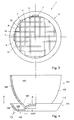
- a series of first channel-like recesses 11, which extend parallel to one another, is provided in the top surface P
- a second series of channel-like recesses 12, which likewise extend parallel to one another and extend at right angles to the direction of the first channel-like recesses 11, is also provided in the top surface P, as shown in Fig. 3. Therefore, the channel-like recesses 11, 12 delimit small, substantially square islands 13, the top sides of which define the top surface P.
- the channel-like recesses 11, 12 have a width B and a depth D which are selected in such a manner that the channel-like recesses 11, 12, during normal use, are not filled, or at least are not completely filled, with soil or similar growth medium, and moreover such that roots of the plant are prevented from extending into the channel-like recesses. This means that the channel-like recesses 11, 12 remain substantially available for transporting and storing water, nutrients and/or air to the top surface P and therefore to the roots of the plant, without these roots or the growth medium being in constant contact with water.
- a holder 1 in accordance with Fig. 1 can be used as follows.
- the holder 1 is placed with its base 3 on an ebb and flood base, after which water is cyclically introduced onto the ebb and flood base to a level which lies above the plane V and then discharged again.
- the holding space 8 will fill up, as will the channel-like recesses 11, 12. This water remains behind in the holder 1 even when the water is discharged from the ebb and flood base.
- the plant can then, when required, withdraw water from the channel-like recesses 11, 12 and, if appropriate, from the holding space 8, while permanent contact with the water is easily prevented.
- water can also be introduced into the holding space 8 in other ways, for example using a watering can or similar means, or with the aid of sprayer devices or the like above the plant.
- Fig. 4 shows an alternative embodiment of a holder 101 according to the invention, provided with an integral dish 105 and an elevated base part 103A.
- the internal space 106 inside the circumferential wall 102 is again in fluid communication with the holding space 108 of the dish 105 via the openings 107.
- the top side 110 of the raised rim 109 again defines a plane V which lies slightly above the top surface P.
- a number of channels 111 which extend in a single direction and, for example, in meandering form, next to one another, and are connected to at least one opening 107, are again arranged in the base 103 with the aid of profiling.
- An integral hinge 115 is arranged between the rim 109 of the dish and the base 103.
- rim 109 folded downwards (as seen in Fig. 3).
- the integral hinge 115 allows this rim to be folded upwards in a particularly simple manner.
- a holder 101 of this type can be used in the manner described above.
- the difference in level between the planes V and P provides the advantage that when the dish is completely full a relatively small fraction of the growth medium in the internal space 106 is always in direct contact with the water, while when the dish 105 is partially empty this direct contact is avoided.
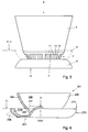
- Fig. 5 shows a holder in accordance with Fig. 1, in side view, with the dish 5 folded downwards.
- the holder is injection-moulded in this state. It is in this case possible to introduce mould parts from the side so as to form at least the openings 7.
- the small islands 13 and the channels 11 which lie between them can be seen through the openings 7.
- the openings 7, 107 will themselves generally be impossible or difficult to see, and this has a beneficial effect on the appearance of the holder.
- the dish 5, 105 is folded back, in such a manner that the raised rim extends from the base 3 in the same direction as the circumferential wall 4, 104. This makes the holder ready for immediate use.
- Fig. 6 shows a second alternative embodiment of a holder 202 according to the invention, which is provided with an integral dish 205 and an elevated base section 203A.
- the internal space 206 is again in fluid communication with the holding space 208.
- the plane V defined by the top side 210 ofthe raised rim 209 lies slightly below the top surface P of the base 203.
- the rim 209 of the dish is of tapering design.
- the wall thickness is approximately 1.3 mm, while in the vicinity of the attachment to the base 203, the wall thickness is approximately 0.3 mm. It will be understood that such tapering outwardly can be used for all the previous variants and all other variants which could be considered by a person skilled in the art, even without an elevated base.
- This curvature makes it advantageously possible to make use of shrinkage which occurs after the injection-moulded holder is removed from the mould.
- the holder is in the position shown in dashed lines immediately after it is demoulded. In this position, demoulding is comparatively simple. After shrinkage and ambient cooling, the position shown in continuous lines is reached. A raised rim designed with such a curvature could not be removed from a mould without special measures.
- the difference in levels between the planes V and P offers the advantage that when the dish is completely full all the growth medium in the internal space 206 always extends above the plane V, thus preventing plant roots from extending continuously into the water.
- the water is again raised, on an ebb and flood base, at least to above the plane P, or the plant is provided with water from the top, so that the growth medium absorbs sufficient water, after which the surplus water can flow out to the holding space 208 until it lies below the plane P.
- An embodiment of this type is particularly simple to produce.
- an embodiment of this nature may also be provided with channel-like recesses.
- the plane P may always lie slightly below, level with or slightly above the plane V, depending on the desired contact between water and growth medium.
- an insert piece to form the elevated section of the base, which insert piece may, if appropriate, be fixedly connected to the base.
- An insert piece of this nature may, for example, be designed in the form of a grid.
- the openings may lie entirely or partially in the plane P or, for example, in a plane which extends parallel thereto, in such a manner that the openings are essentially open towards the bottom. This design is even more successful than that with the openings in an inclined surface in preventing the openings from being visible from the outside.
- the holder may have any desired external shape, for example may be round, elliptical, rectangular or polygonal.
- a holder according to the invention may be formed in some other way, for example using moulds with suitable cores, slides and the like, with the result that, for example, the holding space 8 of the dish 5 is formed by die parts which extend through substantially encircling openings, partitions in the dish being formed between these die parts.
- the dish may substantially adjoin the circumferential wall of the holder, in such a manner that water can flow through a relatively narrow annular gap between dish and holder.
Landscapes
- Life Sciences & Earth Sciences (AREA)
- Environmental Sciences (AREA)
- Cultivation Receptacles Or Flower-Pots, Or Pots For Seedlings (AREA)
Applications Claiming Priority (2)
| Application Number | Priority Date | Filing Date | Title |
|---|---|---|---|
| NL1008498 | 1998-03-05 | ||
| NL1008498A NL1008498C2 (nl) | 1998-03-05 | 1998-03-05 | Houder voor planten en dergelijke. |
Publications (1)
| Publication Number | Publication Date |
|---|---|
| EP0940073A1 true EP0940073A1 (de) | 1999-09-08 |
Family
ID=19766672
Family Applications (1)
| Application Number | Title | Priority Date | Filing Date |
|---|---|---|---|
| EP99200657A Withdrawn EP0940073A1 (de) | 1998-03-05 | 1999-03-05 | Behälter für Pflanzen und dergleichen |
Country Status (2)
| Country | Link |
|---|---|
| EP (1) | EP0940073A1 (de) |
| NL (1) | NL1008498C2 (de) |
Cited By (4)
| Publication number | Priority date | Publication date | Assignee | Title |
|---|---|---|---|---|
| NL1020443C2 (nl) * | 2002-04-22 | 2003-10-23 | Aufderhaar Plastic Ind B V | Houder voor gewassen met neerwaarts hellend bodemdeel voorzien van afwateringsgaten. |
| FR2847118A1 (fr) * | 2002-11-19 | 2004-05-21 | Jean Michel Albert Ghiglione | Dispositif de drainage d'eau d'arrosage pour pot de fleurs |
| WO2018006123A1 (en) * | 2016-07-08 | 2018-01-11 | Rodney James Middleton | An improved plant pot |
| US10342183B2 (en) * | 2015-01-26 | 2019-07-09 | Plantlogic LLC | Stackable pots for plants |
Citations (9)
| Publication number | Priority date | Publication date | Assignee | Title |
|---|---|---|---|---|
| US3949524A (en) * | 1975-02-25 | 1976-04-13 | Mickelson Richard C | Planter |
| FR2374840A2 (fr) * | 1976-04-06 | 1978-07-21 | Ami | Bac a reserve d'eau pour la culture des plantes |
| FR2602639A1 (fr) * | 1986-08-14 | 1988-02-19 | Faraud Francois | Pot de culture a humidite constante et reserve d'eau |
| EP0351030A1 (de) * | 1988-07-20 | 1990-01-17 | Emperor Plastics B.V. | Pflanzentopf sowie Verfahren und Form zu seiner Herstellung |
| EP0381023A2 (de) * | 1989-02-01 | 1990-08-08 | Riesselmann & Sohn | Pflanzentopf-Herstellungsverfahren und nach diesem Verfahren erzeugte Produkte |
| FR2664467A1 (fr) * | 1990-07-12 | 1992-01-17 | Clarous Freres Cie | Dispositif pour recueillir l'excedent d'eau d'arrosage et pour hydrater un pot de fleurs en matiere poreuse. |
| FR2699045A1 (fr) * | 1992-12-11 | 1994-06-17 | Chatelet | Récipient pour plantes. |
| FR2716070A1 (fr) * | 1994-02-16 | 1995-08-18 | Soparco Sa | Récipient à pied déformable pouvant servir de soucoupe. |
| EP0727136A1 (de) * | 1995-02-20 | 1996-08-21 | Heli Plastic B.V. | Gegenstand mit einem herausragenden Flansch |
-
1998
- 1998-03-05 NL NL1008498A patent/NL1008498C2/nl not_active IP Right Cessation
-
1999
- 1999-03-05 EP EP99200657A patent/EP0940073A1/de not_active Withdrawn
Patent Citations (9)
| Publication number | Priority date | Publication date | Assignee | Title |
|---|---|---|---|---|
| US3949524A (en) * | 1975-02-25 | 1976-04-13 | Mickelson Richard C | Planter |
| FR2374840A2 (fr) * | 1976-04-06 | 1978-07-21 | Ami | Bac a reserve d'eau pour la culture des plantes |
| FR2602639A1 (fr) * | 1986-08-14 | 1988-02-19 | Faraud Francois | Pot de culture a humidite constante et reserve d'eau |
| EP0351030A1 (de) * | 1988-07-20 | 1990-01-17 | Emperor Plastics B.V. | Pflanzentopf sowie Verfahren und Form zu seiner Herstellung |
| EP0381023A2 (de) * | 1989-02-01 | 1990-08-08 | Riesselmann & Sohn | Pflanzentopf-Herstellungsverfahren und nach diesem Verfahren erzeugte Produkte |
| FR2664467A1 (fr) * | 1990-07-12 | 1992-01-17 | Clarous Freres Cie | Dispositif pour recueillir l'excedent d'eau d'arrosage et pour hydrater un pot de fleurs en matiere poreuse. |
| FR2699045A1 (fr) * | 1992-12-11 | 1994-06-17 | Chatelet | Récipient pour plantes. |
| FR2716070A1 (fr) * | 1994-02-16 | 1995-08-18 | Soparco Sa | Récipient à pied déformable pouvant servir de soucoupe. |
| EP0727136A1 (de) * | 1995-02-20 | 1996-08-21 | Heli Plastic B.V. | Gegenstand mit einem herausragenden Flansch |
Cited By (6)
| Publication number | Priority date | Publication date | Assignee | Title |
|---|---|---|---|---|
| NL1020443C2 (nl) * | 2002-04-22 | 2003-10-23 | Aufderhaar Plastic Ind B V | Houder voor gewassen met neerwaarts hellend bodemdeel voorzien van afwateringsgaten. |
| FR2847118A1 (fr) * | 2002-11-19 | 2004-05-21 | Jean Michel Albert Ghiglione | Dispositif de drainage d'eau d'arrosage pour pot de fleurs |
| US10342183B2 (en) * | 2015-01-26 | 2019-07-09 | Plantlogic LLC | Stackable pots for plants |
| WO2018006123A1 (en) * | 2016-07-08 | 2018-01-11 | Rodney James Middleton | An improved plant pot |
| CN109475093A (zh) * | 2016-07-08 | 2019-03-15 | 罗德尼·詹姆斯·米德尔顿 | 改进花盆 |
| CN109475093B (zh) * | 2016-07-08 | 2023-03-07 | 罗德尼·詹姆斯·米德尔顿 | 改进花盆 |
Also Published As
| Publication number | Publication date |
|---|---|
| NL1008498C2 (nl) | 1999-09-10 |
Similar Documents
| Publication | Publication Date | Title |
|---|---|---|
| US5638638A (en) | Flower pot with accessible watering base | |
| US2893167A (en) | Collapsible plant container | |
| US20170245465A1 (en) | Pet fountains | |
| US3799493A (en) | Mold for congealable foodstuffs and the like | |
| US6185863B1 (en) | Block for sticking natural flowers, branches and the like | |
| ITBO980395A1 (it) | Stampi per fabbricazione di bicchieri di ghiaccio e supporti per soste nere tali bicchieri durante l' impiego . | |
| US20080141587A1 (en) | Planter container inserts | |
| FI59010C (fi) | Flerdelat uppsaettningsarrangemang foer vaexter | |
| EP0940073A1 (de) | Behälter für Pflanzen und dergleichen | |
| WO2020168067A1 (en) | Self-watering planter | |
| JP5788366B2 (ja) | 給水式プランター装置 | |
| EP0452388A1 (de) | Anordnung an röhrförmigen zuchtbehältern für pflanzen | |
| US20080052993A1 (en) | Flowerpot Having Automatic Water Feed Function | |
| WO2000048451A1 (en) | Cultivation tray | |
| JP3007913B2 (ja) | 栽培容器 | |
| ES2187213T3 (es) | Recipiente moldeado por soplado provisto de nervaduras de refuerzo y metodo y aparato para su fabricacion. | |
| US12114618B2 (en) | Rain cloud | |
| JPH0227832Y2 (de) | ||
| KR200369931Y1 (ko) | 화분파렛트 | |
| CN216931021U (zh) | 花盆蓄水缸和花盆 | |
| AU2004100293B4 (en) | Soil Separators And Self-Watering Pots | |
| JP3064095U (ja) | 植木鉢 | |
| JPH0232041Y2 (de) | ||
| JP2004275009A (ja) | 植栽用パレット | |
| JP3031562U (ja) | ジョウロ |
Legal Events
| Date | Code | Title | Description |
|---|---|---|---|
| PUAI | Public reference made under article 153(3) epc to a published international application that has entered the european phase |
Free format text: ORIGINAL CODE: 0009012 |
|
| AK | Designated contracting states |
Kind code of ref document: A1 Designated state(s): BE DE FR GB IT NL |
|
| AX | Request for extension of the european patent |
Free format text: AL;LT;LV;MK;RO;SI |
|
| 17P | Request for examination filed |
Effective date: 20000308 |
|
| AKX | Designation fees paid | ||
| REG | Reference to a national code |
Ref country code: DE Ref legal event code: 8566 |
|
| RBV | Designated contracting states (corrected) |
Designated state(s): AT BE CH CY DE DK LI |
|
| RBV | Designated contracting states (corrected) |
Designated state(s): BE DE FR GB IT NL |
|
| RAP1 | Party data changed (applicant data changed or rights of an application transferred) |
Owner name: BITTER, LAEMBERT Owner name: IMPERIAL PROPERTY B.V. |
|
| 17Q | First examination report despatched |
Effective date: 20020521 |
|
| STAA | Information on the status of an ep patent application or granted ep patent |
Free format text: STATUS: THE APPLICATION IS DEEMED TO BE WITHDRAWN |
|
| 18D | Application deemed to be withdrawn |
Effective date: 20030909 |