EP0940106A2 - Elément de bordure - Google Patents
Elément de bordure Download PDFInfo
- Publication number
- EP0940106A2 EP0940106A2 EP99103031A EP99103031A EP0940106A2 EP 0940106 A2 EP0940106 A2 EP 0940106A2 EP 99103031 A EP99103031 A EP 99103031A EP 99103031 A EP99103031 A EP 99103031A EP 0940106 A2 EP0940106 A2 EP 0940106A2
- Authority
- EP
- European Patent Office
- Prior art keywords
- component
- elongated edge
- edge element
- wall
- components
- Prior art date
- Legal status (The legal status is an assumption and is not a legal conclusion. Google has not performed a legal analysis and makes no representation as to the accuracy of the status listed.)
- Withdrawn
Links
Images
Classifications
-
- A—HUMAN NECESSITIES
- A47—FURNITURE; DOMESTIC ARTICLES OR APPLIANCES; COFFEE MILLS; SPICE MILLS; SUCTION CLEANERS IN GENERAL
- A47B—TABLES; DESKS; OFFICE FURNITURE; CABINETS; DRAWERS; GENERAL DETAILS OF FURNITURE
- A47B21/00—Tables or desks for office equipment, e.g. typewriters, keyboards
- A47B21/06—Tables or desks for office equipment, e.g. typewriters, keyboards characterised by means for holding, fastening or concealing cables
-
- B—PERFORMING OPERATIONS; TRANSPORTING
- B60—VEHICLES IN GENERAL
- B60R—VEHICLES, VEHICLE FITTINGS, OR VEHICLE PARTS, NOT OTHERWISE PROVIDED FOR
- B60R13/00—Elements for body-finishing, identifying, or decorating; Arrangements or adaptations for advertising purposes
- B60R13/02—Internal Trim mouldings ; Internal Ledges; Wall liners for passenger compartments; Roof liners
- B60R13/0206—Arrangements of fasteners and clips specially adapted for attaching inner vehicle liners or mouldings
-
- B—PERFORMING OPERATIONS; TRANSPORTING
- B60—VEHICLES IN GENERAL
- B60R—VEHICLES, VEHICLE FITTINGS, OR VEHICLE PARTS, NOT OTHERWISE PROVIDED FOR
- B60R13/00—Elements for body-finishing, identifying, or decorating; Arrangements or adaptations for advertising purposes
- B60R13/04—External Ornamental or guard strips; Ornamental inscriptive devices thereon
Definitions
- This invention relates to an edge element.
- Such elements are in various branches of industry, e.g. the furniture industry and the Automotive industry, used in a wide variety of applications. That's the way it is common in the furniture industry, for example, table tops with edging provided that both to increase the impact resistance as well as decorative Serves purposes.
- the decorative properties and impact resistance of a Increasing the edge element often becomes a visible part of the element specially shaped surface, for example in the form of a pointed arch or semicircle. It also occasionally appears desirable to do so visible surface with a decorative or protective layer, a film coating or To be embossed. This proves to be the case with a curved surface difficult, so that it would be advantageous if the desired decor on a level Surface applied and only then brought into the desired shape could be.
- the first component is shaped as a flat wall, and the second component is wider than the distance between the connection and the attachment point between the first and second components, so that when Merging the two components the second component is bent and the first component largely retains its shape. This creates a cavity between the walls, which is constant over the entire width
- the thickness and flexibility of the second component is approximately semi-circular Takes shape.
- the thickness and / or stiffness e.g. Shore hardness
- can be over the width of the second component can be varied (e.g. with increasing Distance from the junction of the two components), so that at Merging the first and second components another, not semi-circular shape is created.
- one or more are in the first component integrated or attached structures formed within the Are hollow and snap into place on the inner surface of the second component.
- Structures of this type for example in the form of ribs, can be used to support one serve semicircular second component or this by appropriate Force deformation into another shape. This can be done, for example, by ripping different lengths can be achieved.
- the second component can be supported by Attachment of a parallel reinforcement wall to the cavity facing side of the second component, so that at least one substantial part of the second component is supported.
- the retaining wall will designed to be flexible so that, despite the support effect, it can be combined with the second component can bend.
- the first component of the edge element is designed as a hollow body with a contact surface, for example as a hollow D-shaped Element, so that when the two components are combined, the second Element takes the shape of the contact surface.
- the first Component can also be made solid.
- they have the first component attached structures via brackets for receiving cables, conduits and the same.
- devices for attaching the profile to provide the relevant object - for example a piece of furniture are attached to the first component, alternatively, however, all suitable devices are possible. Holes for mechanical fasteners such as screws, nails or clips can be prefabricated.
- a plug extension is preferably on a flat wall the first component, which is approximately at right angles to the wall and in a corresponding recess on the object in question snaps into place.
- the fastening elements can have different shapes.
- a clip device based on a Plug extension used on the first or the second component. This Extension is in a correspondingly shaped recess on the other Component introduced, which has a narrow tapered opening, so that the barbed plug-in extension snaps into place.
- the edge element can be used with any suitable Production processes - for example as a molded part or by gluing the first and second component - are to be prepared, however, one is preferable Extrusion of the edge element. The most advantageous is the coextrusion of the first and second component from the different plastic qualities or -types. Various plastics, e.g. PVC, ABS and PP, but also many others are suitable for this.
- Another aspect of the invention is a method of making an ornate or edge element coated in another form.
- Said procedure involves the manufacture of an edge element according to the above described type, the flat laying of the second component, the application a decorative or protective layer, a film coating, an imprint or an embossing on the second component and the subsequent one Merging the two components.
- the assembly can be done immediately after applying the decorative / protective layer at the production site or be carried out by the fitter immediately before being attached to the object.
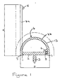
- Figure 1 shows the cross section of an elongated, extruded plastic profile.
- the profile consists of two components that are co-extruded as one piece Element are made.
- the two components are shown in Figure 1 in different directions are hatched; the connecting line of the two Components is marked with 1.
- the first component is made of a hard plastic such as PVC and consists from a first wall 2, which is generally straight.
- Wall 2 has a plug-in extension with barbs 3, with which the profile on an object (not shown) can be attached.
- the second component consists of a soft plastic such as soft PVC and has a second wall 4, which is longer than wall 2.
- a typical length for Wall 2 is 32 mm, wall 4 is 55 mm long.
- the walls 2 and 4 are transverse to each other, if possible, how shown, at right angles, other angles are also possible.
- the edge element becomes the second, initially straight wall Position 4a bent into position 4b, in the exposed edges of the walls 2 and 4 are combined.
- wall 4 with an extension in Arrowhead shape 5 made that fits into recess 6 in wall 1.
- Well 6 has over a narrow tapered neck, which prevents extension 5 easily can be pulled out.
- the element is used, by using the barbed extension 3 or another Device is attached to an object and so as an elongated Edge element is used for a practical purpose to protect the Serves against damage and / or an aesthetic purpose as Decorative profile fulfilled.
- the ends of wall 4 protrude slightly over the edges of wall 2 out (see Figure 7) and are preferably slightly beveled as shown minor irregularities in the surface to which the element is attached, balance and / or some protection against the intrusion of To provide moisture under the assembled element.
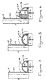
- Figure 2 shows a second embodiment of the invention, in which one out of one Piece with wall 2 formed rib 8 at a right angle about half the length Wall 2 emerges and divides the interior of the element in half.
- rib 8 is so long that there is no change in the natural wall shape takes place, but the rib serves as a support for wall 4.
- the support effect can of course be reinforced by a larger number of ribs.
- FIG 3 An alternative form of support is shown in Figure 3, in which said second component additionally has a reinforcement wall 9 which is parallel to Wall 4 runs on the inside, so that when bending wall 4 from position 4a in position 4b wall 9 is also bent.
- Wall 9 consists of the same hard material, for example PVC hard as wall 2, but has a thinner cross-section so that wall 9, unlike wall 2, is flexible. Therefore, when wall 4 bends, wall 9 takes the arch shape as in Figure 3 shown on, but has natural feather-like properties through which there is always a tendency to return to the starting position; with it works it as an effective support for the soft material of wall 4 and ensures their dimensional stability.
- Figure 4 shows how the shape of wall 2 compared to the otherwise naturally resulting approximately semicircular shape by means of integrated ribs 10, 11, 12 can be changed.
- These ribs were like rib 8 ( Figure 2) in molded in one piece with wall 2, but have lengths through wall 2 in a shape deviating from its natural shape is forced. This can for practical reasons or just for aesthetic reasons be performed.
- the hollow interior of the element can accommodate supply lines such as Pipelines or cables serve and, as shown in Figure 6, ribs with Have brackets. If the cavity, as in Figures 2, 4 and 6, in two or more subjects is divided, the different subjects can be separated Serve different supply lines.
- the outer surface 13 of wall 4 (indicated by the dashed line in the illustrations) can be the only visible part of the element after assembly leave in the original color or provided with a specific coating to achieve the desired decorative effect - such as a wood or stone effect achieve.
- the surface can also be embossed or otherwise in a 3-D look be designed.
- Figure 5 corresponds to Figures 1-4 and 6, differs from them however, in that the first component has a straight wall 2 and a curved support wall 2a, so that a hollow D-profile is formed. If Wall 4 - the second component - from position 4a to position 4b around the first Component is bent, wall 4 takes the shape of the support surface.
- the second component was on one Edge connected to the first component and was connected to this on the other put together, but it is also conceivable that the second component elsewhere (not at the edge) connected to the first component can be, for example in the middle. That would make the second component have two free edges for attachment to the first component.
Landscapes
- Engineering & Computer Science (AREA)
- Mechanical Engineering (AREA)
- Connection Of Plates (AREA)
- Installation Of Indoor Wiring (AREA)
- Vehicle Interior And Exterior Ornaments, Soundproofing, And Insulation (AREA)
- Laminated Bodies (AREA)
Applications Claiming Priority (2)
| Application Number | Priority Date | Filing Date | Title |
|---|---|---|---|
| GBGB9803872.2A GB9803872D0 (en) | 1998-02-24 | 1998-02-24 | Extruded bumper element |
| GB9803872 | 1998-02-24 |
Publications (2)
| Publication Number | Publication Date |
|---|---|
| EP0940106A2 true EP0940106A2 (fr) | 1999-09-08 |
| EP0940106A3 EP0940106A3 (fr) | 2001-01-31 |
Family
ID=10827503
Family Applications (1)
| Application Number | Title | Priority Date | Filing Date |
|---|---|---|---|
| EP99103031A Withdrawn EP0940106A3 (fr) | 1998-02-24 | 1999-02-16 | Elément de bordure |
Country Status (2)
| Country | Link |
|---|---|
| EP (1) | EP0940106A3 (fr) |
| GB (2) | GB9803872D0 (fr) |
Families Citing this family (2)
| Publication number | Priority date | Publication date | Assignee | Title |
|---|---|---|---|---|
| EP1743805A1 (fr) * | 2005-07-15 | 2007-01-17 | WKW Kunststofftechnik AG | Moulure en plastique pour carrosserie de véhicule |
| FR2980428B1 (fr) * | 2011-09-23 | 2013-09-20 | Peugeot Citroen Automobiles Sa | Panneau de protection destine a etre fixe sur une partie de la carrosserie d'un vehicule automobile et procede de fabrication d'un tel panneau. |
Family Cites Families (8)
| Publication number | Priority date | Publication date | Assignee | Title |
|---|---|---|---|---|
| DE1805100A1 (de) * | 1968-10-25 | 1970-05-21 | Kloeber Ohg G | Kantenschutz fuer Holzplatten |
| US4308704A (en) * | 1979-12-10 | 1982-01-05 | Lloyd Ralph E | Trim molding |
| JPS56132141U (fr) * | 1980-03-10 | 1981-10-07 | ||
| US5014486A (en) * | 1988-11-15 | 1991-05-14 | Mayle Robert L | One-piece self-covering termination bar |
| US4903449A (en) * | 1989-05-15 | 1990-02-27 | Ellingson Jr Chester W | Wall corner guard structure |
| DE4326869A1 (de) * | 1993-08-11 | 1995-01-26 | Continental Ag | Profilleiste aus Gummi oder gummiähnlichen Kunststoffen |
| US5836134A (en) * | 1995-02-21 | 1998-11-17 | Boston Metal Products Corp. | Protective bumper railing |
| US5560175A (en) * | 1995-09-13 | 1996-10-01 | Chrysler Corporation | Vehicle body molding with folding flange |
-
1998
- 1998-02-24 GB GBGB9803872.2A patent/GB9803872D0/en not_active Ceased
-
1999
- 1999-01-21 GB GB9901342A patent/GB2334484B/en not_active Expired - Fee Related
- 1999-02-16 EP EP99103031A patent/EP0940106A3/fr not_active Withdrawn
Also Published As
| Publication number | Publication date |
|---|---|
| GB9901342D0 (en) | 1999-03-10 |
| GB2334484B (en) | 2002-02-27 |
| EP0940106A3 (fr) | 2001-01-31 |
| GB9803872D0 (en) | 1998-04-22 |
| GB2334484A (en) | 1999-08-25 |
Similar Documents
| Publication | Publication Date | Title |
|---|---|---|
| DE69307795T2 (de) | Dekorationsschiene | |
| DE60111378T2 (de) | Befestigungsanordnung zum befestigen einer verkleidung an ein fahrzeug | |
| DE2064443C3 (de) | Anordnung zum Befestigen eines langgestreckten Gegenstands an einem paralellen Gegenstand, insbesondere zum Verbinden von Flugzeugwandverkleidungen | |
| DE69207766T2 (de) | Zierleiste für kraftfahrzeuge | |
| DE4435177C2 (de) | Haltersystem für Rohre od. dgl. | |
| EP0428001B1 (fr) | Profilé, en particulier pour véhicules | |
| DE102009009400B4 (de) | Halter zum Fixieren von zylinderförmigen Gegenständen an Belägen und entsprechende Verwendung eines Halters | |
| WO2011124495A2 (fr) | Pince de retenue | |
| DE4103088A1 (de) | Vorrichtung zur ausbildung gleichmaessig verlaufender kanten an bzw. in gebaeuden | |
| EP1426520A1 (fr) | Dispositif de fixation pour panneaux et procédé pour la fixation d'un panneau | |
| DE19853043A1 (de) | Kabelkanal | |
| EP1722064A2 (fr) | Profilé de jonction, notamment profilé de jonction de tableau | |
| DE202017102839U1 (de) | Dreidimensionale Wand- oder Deckenverkleidung | |
| DE19646541C1 (de) | Bausatz miteinander verbindbarer Profilelemente | |
| EP0566134A1 (fr) | Moyens pour la fixation invisible d'un profil | |
| DE3605604A1 (de) | Einteilige klammer | |
| DE102005007269A1 (de) | Leisteneckverkleidung | |
| DE3842687C2 (fr) | ||
| EP0149465B1 (fr) | Montant de paroi | |
| DE102004047941A1 (de) | Verkleidungstafel | |
| DE8109164U1 (de) | Kabelkanalstück zur Herstellung elektrischer Leitungen o.dgl. flexibler Körper | |
| DE69702425T2 (de) | Zaun oder Umschliessung, die leicht herzustellen und zu montieren ist | |
| DE1963213A1 (de) | Abdichtungsvorrichtung fuer Dehnungsfugen | |
| WO2000047835A1 (fr) | Profile support, de jonction ou d'obturation pour un materiau isolant | |
| AT12544U1 (de) | Sockelleistensystem |
Legal Events
| Date | Code | Title | Description |
|---|---|---|---|
| PUAI | Public reference made under article 153(3) epc to a published international application that has entered the european phase |
Free format text: ORIGINAL CODE: 0009012 |
|
| AK | Designated contracting states |
Kind code of ref document: A2 Designated state(s): BE DE ES FR IT |
|
| AX | Request for extension of the european patent |
Free format text: AL;LT;LV;MK;RO;SI |
|
| PUAL | Search report despatched |
Free format text: ORIGINAL CODE: 0009013 |
|
| AK | Designated contracting states |
Kind code of ref document: A3 Designated state(s): AT BE CH CY DE DK ES FI FR GB GR IE IT LI LU MC NL PT SE |
|
| AX | Request for extension of the european patent |
Free format text: AL;LT;LV;MK;RO;SI |
|
| 17P | Request for examination filed |
Effective date: 20010305 |
|
| AKX | Designation fees paid |
Free format text: BE DE ES FR IT |
|
| 17Q | First examination report despatched |
Effective date: 20020611 |
|
| STAA | Information on the status of an ep patent application or granted ep patent |
Free format text: STATUS: THE APPLICATION IS DEEMED TO BE WITHDRAWN |
|
| 18D | Application deemed to be withdrawn |
Effective date: 20021022 |