EP0940192A2 - Behälterreinigungsvorrichtung und Verwendung einer solchen Vorrichtung - Google Patents
Behälterreinigungsvorrichtung und Verwendung einer solchen Vorrichtung Download PDFInfo
- Publication number
- EP0940192A2 EP0940192A2 EP99200664A EP99200664A EP0940192A2 EP 0940192 A2 EP0940192 A2 EP 0940192A2 EP 99200664 A EP99200664 A EP 99200664A EP 99200664 A EP99200664 A EP 99200664A EP 0940192 A2 EP0940192 A2 EP 0940192A2
- Authority
- EP
- European Patent Office
- Prior art keywords
- jaw
- carriage
- container
- tongs
- wheels
- Prior art date
- Legal status (The legal status is an assumption and is not a legal conclusion. Google has not performed a legal analysis and makes no representation as to the accuracy of the status listed.)
- Withdrawn
Links
Images


Classifications
-
- B—PERFORMING OPERATIONS; TRANSPORTING
- B08—CLEANING
- B08B—CLEANING IN GENERAL; PREVENTION OF FOULING IN GENERAL
- B08B9/00—Cleaning hollow articles by methods or apparatus specially adapted thereto
- B08B9/08—Cleaning containers, e.g. tanks
- B08B9/093—Cleaning containers, e.g. tanks by the force of jets or sprays
-
- B—PERFORMING OPERATIONS; TRANSPORTING
- B08—CLEANING
- B08B—CLEANING IN GENERAL; PREVENTION OF FOULING IN GENERAL
- B08B9/00—Cleaning hollow articles by methods or apparatus specially adapted thereto
- B08B9/08—Cleaning containers, e.g. tanks
- B08B9/087—Cleaning containers, e.g. tanks by methods involving the use of tools, e.g. brushes, scrapers
Definitions
- the present invention relates to an apparatus for cleaning containers and other tanks and transport cases, which apparatus may be displaced longitudinally along a longitudinal axis of the container from a staring position outside the container and inwards through an opening in the container, and which apparatus has a carriage intended to be displaced forward and inward through the container and subsequently backwards out of the container, and which is provided with washing means and drying means for washing and drying of the container as the carriages are displaced forward or backward in the container, and which apparatus is provided with at least one jaw-tongs mechanism for displacing the carriage forward and backward through the container.
- the invention also relates to the use of such an apparatus.
- Containers are used as a term for all kinds of containers in freight or storage containers.
- Container may thus both be real freight containers, may be load compartments on lorries or on trailers for lorries, may be independent tanks or tanks on lorries or the trailers of these, or may be quite other kinds of containers.
- EP 256,699 describes an apparatus of this kind for cleaning the inner of bodies of carriages on e.g. lorries or on trailers for lorries.
- the apparatus comprises a trolley mounted before a jaw-tongs mechanism which is mounted on a construction fixed in relation to the trolley.
- the jaw-tongs mechanism is capable of controlling the trolley if the inner of the carriage body is not completely aligned relative to a travelling direction for the trolley.
- the trolley is provided with laterally directed wheels intended for making contact between the trolley and the inner sides of the carriage body and thereby is capable of maintaining the achieved travelling direction of the trolley relative to the carriage body.
- the trolley is also provided with the laterally directed wheels keeping the initial direction as it is just not possible subsequently to perform a further alignment with the jaw-tongs mechanism, but only possible to use the jaw-tongs mechanism for displacing the trolley forward and backward through the carriage body.
- the jaw-tongs mechanism By providing a jaw-tongs mechanism directed in a vertical plane, the jaw-tongs mechanism will have its greatest flexibility in a vertical plane which is of less importance for guiding the carriage as the carriage rests on the bottom of the container and thus does not have to be controlled upwards or downwards, but only has to be guided in lateral direction. Lateral stability of the jaw-tongs mechanism is very great as the single links in the jaw-tongs mechanism are rigid. Simultaneously, it will not be necessary either to support the jaw-tongs mechanism with e.g. wheels in lateral direction as the jaw-tongs mechanism will not bend when the jaw-tongs mechanism is situated in a vertical plane.
- the apparatus is peculiar in that a number of links on the jaw-tongs mechanism are provided with wheels disposed lowermost on the links.
- Disposing wheels under the jaw-tongs mechanism implies that the travel of the carriage becomes easy as the weight of the jaw-tongs mechanism itself does not cause problems with guiding and moving the carriage.
- the wheels are mounted on journals with a certain given length which means that the wheels are placed with a relatively large mutual distance.
- a jaw-tongs mechanism over each set of wheels and both jaw-tongs mechanisms are mutually connected transversely of the direction of travel of the carriage.
- the jaw-tongs mechanism then constitutes a closed structure with very great rigidity in lateral direction so that when the car initially is directed inwards in the correct direction of travel, the jaw-tongs mechanism will cause that this direction will be maintained during the whole movement forward and backward.
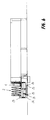
- Fig. 1 shows an embodiment for an apparatus according to the invention.
- the apparatus comprises a carriage 1 with cleaning means (see Fig. 2 and Fig. 3) together with two jaw-tongs mechanisms 2 placed behind the carriage.
- two jaw-tongs mechanisms another number, e.g. a single jaw-tongs mechanism, may be placed behind the carriage.
- the carriage 1 runs on wheels 3 mounted under and foremost on the carriage.
- Rotating brushes 4 are mounted lowermost and forward and outward against the side of carriage 1 on each side of the wheels 3.
- Spraying pipes 5,6 with nozzles (see Fig. 5) for flushing with a fluid detergent is mounted on the carriage 1 uppermost and along the sides of the carriage.
- the laterally directed spraying pipes 5 are mounted on arms 7 which are pivotable relative to the carriage 1 about vertical axes.
- the lateral spraying pipes 5 may be pivoted laterally inward and outward by rotating the arms 7 about the vertical axis.
- the uppermost nozzle beam 6 is mounted on vertical telescopic guides 8 (see Fig. 2). The uppermost nozzle beam 6 may thus be displaced upwards and downwards by displacing the vertical telescopic guides 8.
- the carriage 1 is mounted to the foremost link 10 on the two jaw-tongs mechanisms 2.
- the jaw-tongs mechanisms 2 extend as mentioned backward relative to the carriage 1.
- the rear part of the jaw-tongs mechanisms 2 is intended to be held fixed relative to a fixed starting point (not shown) for the travel of the carriage 1.
- the jaw-tongs mechanisms 2 are placed in parallel at a distance A (see Fig. 3) from each other and both jaw-tongs mechanisms 2 extend in a mainly vertical plane P (see Fig. 3).
- transverse rods 12 Between fittings 11 on the two jaw-tongs mechanisms 2, there is mounted transverse rods 12.
- the carriage 1 is moved forward by at least the wheels 3 on the carriage being driven by a motor (not shown).
- the motor may be powered electrically, hydraulically, pneumatically, or in another way.
- a preferred way to power the motor 3 on the carriage 1 is by means of water or other fluid detergent which is led to the motor via hoses (not shown), and where the water or other detergent subsequently is led to the rotating brushes 4 and to the spraying pipes 5,6 for cleaning the container.
- one or more sets of wheels 13 on the jaw-tongs mechanisms 2 are driven simultaneously with or instead of the wheels 3 on the carriage 1.
- Fig. 2 shows the apparatus from the side.
- the apparatus comprises as mentioned a carriage 1 with cleaning means to be moved forwards and backwards through the container together with two jaw-tongs mechanisms 2 for moving the carriage 1 forward and backward.
- the carriage 1 comprises a chassis and is provided with the wheels 3 driving the carriage forward.
- the carriage is provided with rotating brushes 4, lateral vertical spraying pipes 5 and the horizontal spraying pipes 6.
- the vertical spraying pipes 5 are as mentioned mounted on arms 7 which are pivotable about vertical axis
- the horizontal spraying pipe 6 is as mentioned mounted on telescopic guides 8 that may be displaced upward and downward.
- the rearmost part of the carriage 1 is connected with the jaw-tongs mechanisms 2.
- the jaw-tongs mechanisms 2 constitute semi-jaw-tongs mechanisms with members 14,15 mutually connected with the fittings 11.
- a first member 14 and a second member 15 constitute a foremost link on the jaw-tongs mechanisms 2.
- Other links on the jaw-tongs mechanisms 2 consist also of a first member 14 and a second member 15.
- the wheels 13 are mounted on lowermost fittings 11 of the jaw-tongs mechanisms 2 so that the jaw-tongs mechanisms are supported when the jaw-tongs mechanisms are moved forward simultaneously with the carriage being moved forward.
- each link 10 When the jaw-tongs mechanisms 2 become displaced forward, the members 14,15 in each link 10 become moved forward either by the foremost link 10 moving completely forward before the displacement of one or more subsequent successive links 10 is commenced, or by each link 10 being displaced relatively equally forward simultaneously (see Fig. 6).
- one or more of the members in the single links are provided with a knee joint (not shown) so that the single members may bend in knee joints between the lowermost fittings 11 and the uppermost fittings 11. Thereby the jaw-tongs mechanisms 2 may be displaced into containers that are lower.
- Fig. 3 shows the carriage 1 as seen from the front.
- the jaw-tongs mechanisms 2 behind the carriage 1 are also shown.
- the carriage 1 comprises as mentioned a chassis 9 and is provided with two wheels 3 supporting the carriage foremost.
- the rotating brushes 4 are mounted on each of the wheels 3 and are directed inclined inwards so that the outermost of brush hair of the rotating brushes 4 achieves the strongest abutment on the bottom of the container.
- the lateral spraying pipes 5 are pivoted outwards on the pivotable arms 7.
- the horizontal spraying pipes 6 are displaced upwards to a level at the upper side of the lateral spraying pipes 5.
- Behind the carriage 1, the jaw-tongs mechanisms 2 are shown with the foremost first members 14,15 (see Fig. 2), fittings 11, and transverse rods 12 between the jaw-tongs mechanisms 2 for keeping the jaw-tongs mechanisms at a distance A from each other.
- Fig. 4 shows a rotating brush 4 mounted foremost and lowermost on the carriage 1 on each side of the wheels (not shown) on the carriage.
- the rotating brush is mounted on arms 16,17 which are pivotable relative to the chassis 9 of the carriage about vertical axes.
- a motor 18 is mounted upon the brush 4 for rotating the brush.
- the motor 18 may be electrical, hydraulic, or pneumatic.
- the brush 4 is provided with a disc 19 rotating together with the brush 4.
- the disc 19 is provided with a collar 20 turning upwards and which is coated with a friction creating material. When the carriage 1 is moved forward, the collar 20 on the disc is intended to bear against the side of the container. Because the disc 19 is provided with a friction creating material, and because the brush 4 rotates when the carriage 1 is moved forwards, the collar 20 on the disc 19 will aid in driving the carriage 1 forward.
- Fig. 5 shows a possible embodiment of a vertical and/or horizontal spraying pipe 5,6.
- the spraying pipe 5,6 consists of a pipe provided with holes 21 constituting nozzles. Water or other detergent is intended to be led through the pipe and out through the holes 21 in order to, as shown, create a spray fan 22 of detergent.
- the spray fans 22 from respective nozzles 21 are overlapping so that there is achieved a complete covering with detergent along the extension of the spraying pipe. Because the lateral, vertical spraying pipes 5 (see Fig. 3) may be pivoted outwards and because the horizontal spraying pipe 6 may be displaced upwards, it is possible to move the spraying pipes 5,6 so close to the sides and the ceiling, respectively, of the container that the spray fans of detergent are able to wash and flush the sides and the ceiling of the container completely.
- Fig. 6 shows the use of an apparatus as described above for washing the inner of a freight container.
- the apparatus is placed on a platform 23.
- the platform 23 is mounted on a slide 24 with wheels 25.
- the platform 23 may be displaced upwards and downwards relative to the slide 24 so that the apparatus according to the invention may be brought in level with the bottom of the freight container.
- the wheels 25 on the slide 24 run on rails 26 extending perpendicularly to the plane of the paper.
- the carriage constituting a part of the apparatus is moved forward against hitherto closed doors on the freight container.
- the carriage is provided with sensors which at a given distance from the hitherto closed doors on the container open for water or another detergent to the vertical lateral spraying pipes simultaneously with the spraying pipes by means of the arms being pivoted to and fro in front of the doors. In this way the doors are initially cleaned externally. Then the doors on the containers are opened and the carriage is moved in through the opening at one end of the freight container.
- the jaw-tongs mechanisms When the carriage for the apparatus is moved forward, the jaw-tongs mechanisms simultaneously are unfolded by the single links on the jaw-tongs mechanisms being moved forward simultaneously.
- the jaw-tongs mechanisms have a sufficient number of links with a sufficient length in order that the carriage on the apparatus can be moved completely forward to the other end of the freight container.
- the spray of detergent from the spraying pipes and the rotating brushes When the carriage is moved into and forward in the inner of the freight container, the spray of detergent from the spraying pipes and the rotating brushes will successively wash the inner of the container.
- the horizontal spraying pipes are provided with sensors so that if, in the ceiling of the container there is mounted e.g. a refrigerator, the horizontal spraying pipe by means of the telescopic guides will be moved downwards immediately before the refrigerator in order not to hit the refrigerator mounted in the ceiling. Accordingly, the vertical lateral spraying pipes may be provided with corresponding means.
- the apparatus is preferably intended to perform all cleaning operations with a little number of travels through the container, typically between one and three travels depending on what the container has contained the last time, and depending on how thorough a cleaning of the container is desired. Especially, it will be possible to perform a kind of cleaning operation by moving the carriage from one end of the container to the other and to perform another kind of cleaning operation by moving the carnage back from the other end to the first end of the container.
- the apparatus may be provided with means for drying the inner of the container so that the apparatus may dry the inner of the container when the carriage is moved back again against the first end of the container after the carriage has been moved completely forward to the other end of the container and thus spray cleaned the freight container in its full extension.
Landscapes
- Engineering & Computer Science (AREA)
- Mechanical Engineering (AREA)
- Cleaning In General (AREA)
Applications Claiming Priority (2)
| Application Number | Priority Date | Filing Date | Title |
|---|---|---|---|
| DK30398 | 1998-03-06 | ||
| DK30398 | 1998-03-06 |
Publications (2)
| Publication Number | Publication Date |
|---|---|
| EP0940192A2 true EP0940192A2 (de) | 1999-09-08 |
| EP0940192A3 EP0940192A3 (de) | 2000-11-02 |
Family
ID=8092034
Family Applications (1)
| Application Number | Title | Priority Date | Filing Date |
|---|---|---|---|
| EP99200664A Withdrawn EP0940192A3 (de) | 1998-03-06 | 1999-03-08 | Behälterreinigungsvorrichtung und Verwendung einer solchen Vorrichtung |
Country Status (1)
| Country | Link |
|---|---|
| EP (1) | EP0940192A3 (de) |
Cited By (14)
| Publication number | Priority date | Publication date | Assignee | Title |
|---|---|---|---|---|
| EP1166903A2 (de) | 2000-06-28 | 2002-01-02 | IWD ApS | Waschvorrichtung zur Verwendung in einem Gerät zum Reinigen von Behältern |
| WO2003002276A1 (en) * | 2001-06-27 | 2003-01-09 | Container Wash Systems Limited | Container washing apparatus |
| WO2012003105A1 (en) | 2010-07-01 | 2012-01-05 | Siemens Industry, Inc. | Turn down apparatus |
| DE102012024887B4 (de) * | 2012-12-19 | 2016-03-31 | Felix Kathöfer | Vorrichtung zur Behandlung von Fahrzeuginnenräumen mit Behandlungsflüssigkeiten |
| DE102011107167B4 (de) * | 2011-02-04 | 2016-05-19 | Felix Kathöfer | Reinigungsvorrichtung |
| FR3032634A1 (fr) * | 2015-02-17 | 2016-08-19 | 2B Dev | Installation de nettoyage, notamment pour le nettoyage de l'interieur d'une enceinte |
| EP3069799A1 (de) * | 2015-03-18 | 2016-09-21 | Leemans Waste Centre B.V. | Reinigungsanordnung zur reinigung der innenwände eines behälters und kombination aus einer reinigungsvorrichtung und einem zu reinigenden behälter |
| ES2690203A1 (es) * | 2017-05-18 | 2018-11-19 | Istobal, S.A. | Dispositivo de lavado interior de contenedores |
| ES2698266A1 (es) * | 2017-08-01 | 2019-02-01 | Istobal Sa | Dispositivo y metodo de limpieza de espacios cerrados |
| CN113385504A (zh) * | 2021-07-19 | 2021-09-14 | 山东初饮生物科技有限公司 | 生产酸奶的循环式微生物发酵罐自动清洗器 |
| CN113652728A (zh) * | 2021-09-14 | 2021-11-16 | 南通普菲特涂装有限公司 | 一种具有底部杂物高效清理机构的电泳槽 |
| CN115971183A (zh) * | 2022-12-01 | 2023-04-18 | 扬州君耀新材料科技有限公司 | 一种二甲基乙酰胺废液回收清洗装置 |
| EP4647185A1 (de) * | 2024-05-07 | 2025-11-12 | Marine Systems B.V. | Behälterreinigungssystem mit einziehbaren reinigungsarmen |
| DE102019004959B4 (de) * | 2019-03-07 | 2026-02-19 | Patrick Kathöfer | Reinigungsanlage für Fahrzeug- und Container-lnnenräume |
Family Cites Families (6)
| Publication number | Priority date | Publication date | Assignee | Title |
|---|---|---|---|---|
| US4309788A (en) * | 1979-11-27 | 1982-01-12 | Brager Douglas R | Self-contained cleaner for trailer interiors |
| GB8619129D0 (en) * | 1986-08-05 | 1986-09-17 | Jaco Sumal Ltd | Internal body cleaner |
| DE3842132C1 (en) * | 1988-12-12 | 1990-07-19 | Mannesmann Ag, 4000 Duesseldorf, De | Roller table in a band accumulator |
| DE4340528C2 (de) * | 1993-11-29 | 1997-02-20 | Uraca Pumpen | Vorrichtung zur Innenreinigung von Tanks |
| GB2299770A (en) * | 1995-04-11 | 1996-10-16 | Systems | Liquid distribution device |
| US5638845A (en) * | 1995-11-08 | 1997-06-17 | Oliver; Michael A. | Scissor jet cleaning device |
-
1999
- 1999-03-08 EP EP99200664A patent/EP0940192A3/de not_active Withdrawn
Cited By (22)
| Publication number | Priority date | Publication date | Assignee | Title |
|---|---|---|---|---|
| EP1166903A2 (de) | 2000-06-28 | 2002-01-02 | IWD ApS | Waschvorrichtung zur Verwendung in einem Gerät zum Reinigen von Behältern |
| EP1166903A3 (de) * | 2000-06-28 | 2003-07-09 | IWD ApS | Waschvorrichtung zur Verwendung in einem Gerät zum Reinigen von Behältern |
| WO2003002276A1 (en) * | 2001-06-27 | 2003-01-09 | Container Wash Systems Limited | Container washing apparatus |
| GB2392832A (en) * | 2001-06-27 | 2004-03-17 | Container Wash Systems Ltd | Container washing apparatus |
| GB2392832B (en) * | 2001-06-27 | 2004-12-15 | Container Wash Systems Ltd | Container washing apparatus |
| WO2012003105A1 (en) | 2010-07-01 | 2012-01-05 | Siemens Industry, Inc. | Turn down apparatus |
| DE102011107167B4 (de) * | 2011-02-04 | 2016-05-19 | Felix Kathöfer | Reinigungsvorrichtung |
| DE102012024887B4 (de) * | 2012-12-19 | 2016-03-31 | Felix Kathöfer | Vorrichtung zur Behandlung von Fahrzeuginnenräumen mit Behandlungsflüssigkeiten |
| FR3032634A1 (fr) * | 2015-02-17 | 2016-08-19 | 2B Dev | Installation de nettoyage, notamment pour le nettoyage de l'interieur d'une enceinte |
| WO2016132038A1 (fr) * | 2015-02-17 | 2016-08-25 | 2B Developpement | Installation de nettoyage, notamment pour le nettoyage de l'intérieur d'une enceinte |
| EP3069799A1 (de) * | 2015-03-18 | 2016-09-21 | Leemans Waste Centre B.V. | Reinigungsanordnung zur reinigung der innenwände eines behälters und kombination aus einer reinigungsvorrichtung und einem zu reinigenden behälter |
| WO2016146821A1 (en) * | 2015-03-18 | 2016-09-22 | Leemans Waste Centre B.V. | Cleaning assembly for cleaning the inner walls of a container and combination of a cleaning assembly and a container to be cleaned |
| ES2690203A1 (es) * | 2017-05-18 | 2018-11-19 | Istobal, S.A. | Dispositivo de lavado interior de contenedores |
| ES2698266A1 (es) * | 2017-08-01 | 2019-02-01 | Istobal Sa | Dispositivo y metodo de limpieza de espacios cerrados |
| DE102019004959B4 (de) * | 2019-03-07 | 2026-02-19 | Patrick Kathöfer | Reinigungsanlage für Fahrzeug- und Container-lnnenräume |
| CN113385504A (zh) * | 2021-07-19 | 2021-09-14 | 山东初饮生物科技有限公司 | 生产酸奶的循环式微生物发酵罐自动清洗器 |
| CN113652728A (zh) * | 2021-09-14 | 2021-11-16 | 南通普菲特涂装有限公司 | 一种具有底部杂物高效清理机构的电泳槽 |
| CN113652728B (zh) * | 2021-09-14 | 2022-07-01 | 南通普菲特涂装有限公司 | 一种具有底部杂物高效清理机构的电泳槽 |
| CN115971183A (zh) * | 2022-12-01 | 2023-04-18 | 扬州君耀新材料科技有限公司 | 一种二甲基乙酰胺废液回收清洗装置 |
| CN115971183B (zh) * | 2022-12-01 | 2024-01-23 | 扬州君耀新材料科技有限公司 | 一种二甲基乙酰胺废液回收清洗装置 |
| EP4647185A1 (de) * | 2024-05-07 | 2025-11-12 | Marine Systems B.V. | Behälterreinigungssystem mit einziehbaren reinigungsarmen |
| NL2037636B1 (en) * | 2024-05-07 | 2025-11-19 | Marine Systems B V | Container cleaning system with retractable cleaning arms |
Also Published As
| Publication number | Publication date |
|---|---|
| EP0940192A3 (de) | 2000-11-02 |
Similar Documents
| Publication | Publication Date | Title |
|---|---|---|
| EP0940192A2 (de) | Behälterreinigungsvorrichtung und Verwendung einer solchen Vorrichtung | |
| US4924892A (en) | Painting truck washing system | |
| DK173841B1 (da) | Spuleindretning til brug i et apparat til rengøring af containere | |
| US6213135B1 (en) | Linkage assembly for cleaning tankcars | |
| US6317919B1 (en) | Railcar cleaning apparatus | |
| RU2361801C2 (ru) | Способ и устройство для разгрузки ленточных рельсов с железнодорожных вагонов | |
| US3961983A (en) | Apparatus and method for washing interiors of truck and trailer bodies | |
| AU602168B2 (en) | Carriage type conveyor | |
| US8359695B2 (en) | Mechanical sweeper | |
| US11124162B2 (en) | System and method for cleaning and sanitizing the interior of a freight container | |
| US3830430A (en) | Cleaning vehicle | |
| CN113560295B (zh) | 集装箱清洗装置及其清洗方法 | |
| US20080047593A1 (en) | Rollover car wash for large vehicles | |
| US4240175A (en) | Apparatus for washing the interior of a freight container | |
| US20120047667A1 (en) | Mechanical sweeper | |
| CZ347097A3 (cs) | Nákladní vůz na sypký materiál | |
| US4408625A (en) | Article washing means with movable spray heads | |
| US6523221B1 (en) | Railcar cleaning method and apparatus | |
| JP2003522697A (ja) | 車両用荷積み、荷降ろしシステム | |
| US2812867A (en) | Box car unloading apparatus | |
| US20060124154A1 (en) | System and method for washing a vehicle | |
| JP3712214B2 (ja) | 洗浄装置 | |
| CN217649345U (zh) | 一种汽车侧翻清扫机 | |
| US2274313A (en) | Transfer car | |
| CN215696593U (zh) | 自行走清洗装置 |
Legal Events
| Date | Code | Title | Description |
|---|---|---|---|
| PUAI | Public reference made under article 153(3) epc to a published international application that has entered the european phase |
Free format text: ORIGINAL CODE: 0009012 |
|
| AK | Designated contracting states |
Kind code of ref document: A2 Designated state(s): BE DE DK FR GB IT NL SE |
|
| AX | Request for extension of the european patent |
Free format text: AL;LT;LV;MK;RO;SI |
|
| PUAL | Search report despatched |
Free format text: ORIGINAL CODE: 0009013 |
|
| RIC1 | Information provided on ipc code assigned before grant |
Free format text: 7B 08B 9/087 A, 7B 08B 9/093 B |
|
| AK | Designated contracting states |
Kind code of ref document: A3 Designated state(s): AT BE CH CY DE DK ES FI FR GB GR IE IT LI LU MC NL PT SE |
|
| AX | Request for extension of the european patent |
Free format text: AL;LT;LV;MK;RO;SI |
|
| 17P | Request for examination filed |
Effective date: 20010501 |
|
| AKX | Designation fees paid |
Free format text: BE DE DK FR GB IT NL SE |
|
| 17Q | First examination report despatched |
Effective date: 20020613 |
|
| STAA | Information on the status of an ep patent application or granted ep patent |
Free format text: STATUS: THE APPLICATION IS DEEMED TO BE WITHDRAWN |
|
| 18D | Application deemed to be withdrawn |
Effective date: 20030225 |