EP0940244A2 - Verfahren und Vorrichting zur Herstellung von Linsen und mit deren hergestellte Linsen - Google Patents
Verfahren und Vorrichting zur Herstellung von Linsen und mit deren hergestellte Linsen Download PDFInfo
- Publication number
- EP0940244A2 EP0940244A2 EP99102691A EP99102691A EP0940244A2 EP 0940244 A2 EP0940244 A2 EP 0940244A2 EP 99102691 A EP99102691 A EP 99102691A EP 99102691 A EP99102691 A EP 99102691A EP 0940244 A2 EP0940244 A2 EP 0940244A2
- Authority
- EP
- European Patent Office
- Prior art keywords
- molding surface
- lens
- mold
- concave
- functional sheet
- Prior art date
- Legal status (The legal status is an assumption and is not a legal conclusion. Google has not performed a legal analysis and makes no representation as to the accuracy of the status listed.)
- Granted
Links
- 238000000034 method Methods 0.000 title claims abstract description 44
- 238000004519 manufacturing process Methods 0.000 title claims abstract description 22
- 238000000465 moulding Methods 0.000 claims abstract description 135
- 230000002093 peripheral effect Effects 0.000 claims abstract description 55
- 230000008569 process Effects 0.000 claims abstract description 27
- 239000000463 material Substances 0.000 claims abstract description 22
- 125000006850 spacer group Chemical group 0.000 description 6
- 230000005540 biological transmission Effects 0.000 description 2
- 238000010276 construction Methods 0.000 description 2
- 230000007246 mechanism Effects 0.000 description 2
- 230000003287 optical effect Effects 0.000 description 2
- 238000004873 anchoring Methods 0.000 description 1
- 238000007796 conventional method Methods 0.000 description 1
- 230000006866 deterioration Effects 0.000 description 1
- 230000002542 deteriorative effect Effects 0.000 description 1
- 238000002347 injection Methods 0.000 description 1
- 239000007924 injection Substances 0.000 description 1
- 238000012986 modification Methods 0.000 description 1
- 230000004048 modification Effects 0.000 description 1
- 230000000717 retained effect Effects 0.000 description 1
- 230000037303 wrinkles Effects 0.000 description 1
Images



Classifications
-
- B—PERFORMING OPERATIONS; TRANSPORTING
- B29—WORKING OF PLASTICS; WORKING OF SUBSTANCES IN A PLASTIC STATE IN GENERAL
- B29D—PRODUCING PARTICULAR ARTICLES FROM PLASTICS OR FROM SUBSTANCES IN A PLASTIC STATE
- B29D11/00—Producing optical elements, e.g. lenses or prisms
-
- B—PERFORMING OPERATIONS; TRANSPORTING
- B29—WORKING OF PLASTICS; WORKING OF SUBSTANCES IN A PLASTIC STATE IN GENERAL
- B29D—PRODUCING PARTICULAR ARTICLES FROM PLASTICS OR FROM SUBSTANCES IN A PLASTIC STATE
- B29D11/00—Producing optical elements, e.g. lenses or prisms
- B29D11/0073—Optical laminates
-
- B—PERFORMING OPERATIONS; TRANSPORTING
- B29—WORKING OF PLASTICS; WORKING OF SUBSTANCES IN A PLASTIC STATE IN GENERAL
- B29C—SHAPING OR JOINING OF PLASTICS; SHAPING OF MATERIAL IN A PLASTIC STATE, NOT OTHERWISE PROVIDED FOR; AFTER-TREATMENT OF THE SHAPED PRODUCTS, e.g. REPAIRING
- B29C33/00—Moulds or cores; Details thereof or accessories therefor
- B29C33/12—Moulds or cores; Details thereof or accessories therefor with incorporated means for positioning inserts, e.g. labels
- B29C33/14—Moulds or cores; Details thereof or accessories therefor with incorporated means for positioning inserts, e.g. labels against the mould wall
- B29C33/18—Moulds or cores; Details thereof or accessories therefor with incorporated means for positioning inserts, e.g. labels against the mould wall using vacuum
-
- B—PERFORMING OPERATIONS; TRANSPORTING
- B29—WORKING OF PLASTICS; WORKING OF SUBSTANCES IN A PLASTIC STATE IN GENERAL
- B29C—SHAPING OR JOINING OF PLASTICS; SHAPING OF MATERIAL IN A PLASTIC STATE, NOT OTHERWISE PROVIDED FOR; AFTER-TREATMENT OF THE SHAPED PRODUCTS, e.g. REPAIRING
- B29C45/00—Injection moulding, i.e. forcing the required volume of moulding material through a nozzle into a closed mould; Apparatus therefor
- B29C45/14—Injection moulding, i.e. forcing the required volume of moulding material through a nozzle into a closed mould; Apparatus therefor incorporating preformed parts or layers, e.g. injection moulding around inserts or for coating articles
- B29C45/14065—Positioning or centering articles in the mould
-
- B—PERFORMING OPERATIONS; TRANSPORTING
- B29—WORKING OF PLASTICS; WORKING OF SUBSTANCES IN A PLASTIC STATE IN GENERAL
- B29C—SHAPING OR JOINING OF PLASTICS; SHAPING OF MATERIAL IN A PLASTIC STATE, NOT OTHERWISE PROVIDED FOR; AFTER-TREATMENT OF THE SHAPED PRODUCTS, e.g. REPAIRING
- B29C45/00—Injection moulding, i.e. forcing the required volume of moulding material through a nozzle into a closed mould; Apparatus therefor
- B29C45/14—Injection moulding, i.e. forcing the required volume of moulding material through a nozzle into a closed mould; Apparatus therefor incorporating preformed parts or layers, e.g. injection moulding around inserts or for coating articles
- B29C45/14065—Positioning or centering articles in the mould
- B29C2045/14155—Positioning or centering articles in the mould using vacuum or suction
-
- B—PERFORMING OPERATIONS; TRANSPORTING
- B29—WORKING OF PLASTICS; WORKING OF SUBSTANCES IN A PLASTIC STATE IN GENERAL
- B29K—INDEXING SCHEME ASSOCIATED WITH SUBCLASSES B29B, B29C OR B29D, RELATING TO MOULDING MATERIALS OR TO MATERIALS FOR MOULDS, REINFORCEMENTS, FILLERS OR PREFORMED PARTS, e.g. INSERTS
- B29K2995/00—Properties of moulding materials, reinforcements, fillers, preformed parts or moulds
- B29K2995/0018—Properties of moulding materials, reinforcements, fillers, preformed parts or moulds having particular optical properties, e.g. fluorescent or phosphorescent
- B29K2995/0034—Polarising
-
- B—PERFORMING OPERATIONS; TRANSPORTING
- B29—WORKING OF PLASTICS; WORKING OF SUBSTANCES IN A PLASTIC STATE IN GENERAL
- B29L—INDEXING SCHEME ASSOCIATED WITH SUBCLASS B29C, RELATING TO PARTICULAR ARTICLES
- B29L2011/00—Optical elements, e.g. lenses, prisms
- B29L2011/0016—Lenses
-
- Y—GENERAL TAGGING OF NEW TECHNOLOGICAL DEVELOPMENTS; GENERAL TAGGING OF CROSS-SECTIONAL TECHNOLOGIES SPANNING OVER SEVERAL SECTIONS OF THE IPC; TECHNICAL SUBJECTS COVERED BY FORMER USPC CROSS-REFERENCE ART COLLECTIONS [XRACs] AND DIGESTS
- Y10—TECHNICAL SUBJECTS COVERED BY FORMER USPC
- Y10S—TECHNICAL SUBJECTS COVERED BY FORMER USPC CROSS-REFERENCE ART COLLECTIONS [XRACs] AND DIGESTS
- Y10S425/00—Plastic article or earthenware shaping or treating: apparatus
- Y10S425/808—Lens mold
Definitions
- the present invention relates to method and apparatus for manufacturing a lens having a lens body integral with a functional sheet, such as a polarizing sheet or an optical sheet for controlling the light transmission of the lens, on one side thereof by an insert molding process in which the functional sheet is inserted in a mold, and to a lens manufactured thereby.
- a functional sheet such as a polarizing sheet or an optical sheet for controlling the light transmission of the lens
- a method of manufacturing a lens which comprises an insert molding process including the steps of inserting into a mold a polarizing sheet previously formed into a curved surface, and then injecting a molten plastic material into the mold, thereby integrally molding a lens body and the polarizing sheet (refer to, for example, Japanese Examined Patent Publication No. SHO 61-56090).
- a flat peripheral portion around a curved surface portion of preformed polarizing sheet 51 is cut off with a portion retained as a support portion 52 as shown in Fig.
- a support pin 57 is provided on a concave mold part 53 in an area outside a concave molding surface 54 thereof or on a convex mold part 55 in an area outside a convex molding surface thereof;
- the polarizing sheet 51 is gently placed on the concave molding surface 54 or the convex molding surface 56 conformably while the support portion 52 is supported by the support pin 57; and the mold parts 53 and 55 are clamped together and a molten plastic material is filled into a resulting cavity to form a lens having a lens body integral with the polarizing sheet 51.
- a previously formed first lens 64 is placed in position between the mold parts 61 and 62; a vacuum pump is actuated to attract the first lens 64 against the mold part 61 through the suction hole 63 to anchor the first lens 64 onto the mold part 61; and the other mold part 62 is mated with the mold part 61, followed by injection of a molten plastic material into the resulting cavity to afford an intended hybrid lens.
- a peripheral portion of the polarizing sheet 51 is likely to be easily turned up by the inflow pressure of the plastic material or the like, so that the molten plastic material reaches the outward side of the polarizing sheet 51, thus resulting in the polarizing sheet 51 or lens having deteriorated functions.
- lens manufacturing method and apparatus which can securely hold an insert such as a functional sheet on a molding surface of a mold in an insert molding process without any danger of turning up a peripheral portion of the functional sheet and can easily manufacture a lens of good quality without any substantial deterioration in the functions of the functional sheet or lens.
- the present invention provides a method of manufacturing a lens having a lens body integral with a functional sheet on one side thereof, comprising an insert molding process including the steps of: placing the functional sheet as an insert in position in a mold defining a suction hole therein; and while attracting the functional sheet against a molding surface of the mold by a peripheral portion thereof by suction through the suction hole, supplying to the mold a molten plastic material for forming the lens body, to form the lens.
- the functional sheet (or the insert) is attracted and held against the molding surface by a peripheral portion thereof by suction through the suction hole and, hence, the peripheral portion of the functional sheet is prevented from being turned up from the molding surface of the mold. Further, since a mark of the suction hole which results from the suction therethrough is formed in the peripheral portion of the functional sheet, such a suction mark scarcely deteriorates the functions of the functional sheet or lens.
- the present invention yet provides a method of manufacturing a lens having a lens body integral with a functional sheet on one side thereof, comprising an insert molding process including the steps of: placing the functional sheet as an insert in position between a concave molding surface of a concave mold part of a mold and a convex molding surface of a convex mold part of the mold, the concave molding surface having a curvature equal to a curvature of the lens, the convex molding surface having a curvature equal to a curvature of the lens, one of the concave mold part and the convex mold part defining a plurality of suction holes therein; and while attracting the functional sheet against the molding surface of said one of the concave mold part and the convex mold part by a peripheral portion thereof by suction through the plurality of suction holes, supplying into a cavity defined between the concave molding surface of the concave mold part and the convex molding surface of the convex mold part a molten plastic material for forming
- the functional sheet (or the insert) is attracted and held against the concave molding surface of the concave mold part or the convex molding surface of the convex mold part by the peripheral portion thereof by suction through the plurality of suction holes and, hence, the peripheral portion of the functional sheet is prevented from being turned up from the molding surface of one of the concave mold part and the convex mold part at plural points in the insert molding process.
- marks of the suction holes which result from the suction therethrough are formed in the peripheral portion of the functional sheet and since each suction mark can be minimized in size by virtue of the provision of the plurality of suction holes, such suction marks scarcely deteriorate the functions of the functional sheet or lens.
- the functional sheet to be placed in position in the mold may be previously shaped to match the configuration of the lens body.
- the suction hole or the plurality of suction holes may be located in a portion of the molding surface within 10 mm inwardly from a line corresponding in location to a peripheral edge of the lens. This feature allows the suction mark(s) to be formed in the peripheral portion of the functional sheet within 10 mm inwardly from the peripheral edge of the lens.
- the functional sheet or the lens can more reliably be prevented from being deteriorated in their functions.
- the peripheral portion of the functional sheet can more assuredly be prevented from being turned up from the molding surface of the mold.
- the plurality of suction holes open the concave molding surface of the concave mold part.
- the suction hole or each of the plurality of suction holes preferably defines an opening having a diameter of about 0.1 to about 1.0 mm in the molding surface. This enables each resulting suction mark on the functional sheet to have a size of about 0.1 to about 1.0 mm. Thus, the functional sheet or the lens is more assuredly prevented from being deteriorated in their functions.
- the mold is preferably provided with an O-ring between mold components thereof for preventing outside air from entering the suction hole(s). Thus, an unexpected decrease in the suction force can be avoided.
- the present invention further provides apparatus for manufacturing a lens having a lens body integral with a functional sheet on one side thereof, the apparatus comprising a mold for performing an insert molding process to form the lens, wherein: the mold has a molding surface for receiving the functional sheet as an insert in position and a molten plastic material for forming the lens body; and a suction hole is defined in the mold for attracting the functional sheet against the molding surface by a peripheral portion of the functional sheet by suction therethrough.
- the peripheral portion of the functional sheet is prevented from being turned up from the molding surface of the mold in the insert molding process. Further, it is possible to locate a suction mark resulting from the suction through the suction hole in the peripheral portion of the functional sheet. The suction mark in such location scarcely deteriorates the functions of the functional sheet or lens.
- the present invention still provides apparatus for manufacturing a lens having a lens body integral with a functional sheet on one side thereof, the apparatus comprising a mold for performing an insert molding process to form the lens, the mold including a concave mold part having a concave molding surface, and a convex mold part having a convex molding surface, wherein: the concave molding surface has a curvature equal to a curvature of the lens, while the convex molding surface has a curvature equal to a curvature of the lens; one of the concave molding surface and the convex molding surface is configured to receive the functional sheet as an insert in position; one of the concave mold part and the convex mold part defines a plurality of suction holes therein for attracting the functional sheet against said one of the concave molding surface and the convex molding surface by a peripheral portion of the functional sheet by suction therethrough; and the concave molding surface and the convex molding surface together define a cavity therebetween for receiving a molten plastic material for
- the peripheral portion of the functional sheet is prevented at plural points from being turned up from the molding surface. Further, it is possible to minimize in size each suction mark to be formed in the peripheral portion of the functional sheet. Such small suction marks in the peripheral portion of the functional sheet scarcely deteriorate the functions of the functional sheet or lens.
- the present invention still further provides a lens comprising a lens body, and a functional sheet formed integrally with the lens body on one side thereof by an insert molding process, the functional sheet having a plurality of suction marks in a peripheral portion thereof resulting from attraction of the functional sheet against a molding surface of a mold by suction in the insert molding process.
- this lens is manufactured by the insert molding process in which the functional sheet as an insert is attracted at plural points by the peripheral portion thereof against the molding surface of the mold by suction, the peripheral portion of the functional sheet is prevented from being turned up from the molding surface in the insert molding. Further, the suction marks are not formed in the central portion but in the peripheral portion of the functional sheet, thus resulting in the lens of good quality with its functions scarcely deteriorated by such suction marks.
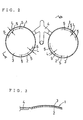
- a pair of lenses 1 each have a lens body 2 formed of a plastic material and a polarizing sheet 3, as a functional sheet, integral with the lens body 2 on the front side (the convex side) of the lens body 2.
- the pair of lenses 1 are interconnected through a connection member 4 which is formed integrally with the lens bodies 2 using the same plastic material as the lens bodies 2 by molding.
- the functional sheet 3 has a peripheral portion formed with a plurality of suction marks 5 slightly projecting forward. These suction marks 5 result from suction through suction holes 23 defined in a mold to be described later.
- the connection member 4 is cut off from the pair of lens bodies 2 to separate the lenses 1 from each other at an appropriate step following the molding process.
- lens manufacturing apparatus for insert-molding the lens 1 includes a concave mold part 8 and a convex mold part 9.
- the concave mold part 8 has a concave molding surface 8a having a curvature equal to that of the corresponding side of the lens 1, while the convex mold part 9 has a convex molding surface 9a having a curvature equal to that of the corresponding side of the lens 1.
- a cavity 10 is defined between these molding surfaces 8a and 9a.
- the concave mold part 8 is fitted in and held by an annular holding member 13, which in turn is secured to a fixing plate 14 by a fastening member not shown.
- a spacer 15 is provided between the fixing member 14 and the concave mold part 8.
- the convex mold part 9 is fitted in and held by an annular holding member 17, which in turn is secured to a movable plate 19 with an intervening member 18 therebetween by a fastening member not shown.
- a spacer 20 is provided between the movable plate 19 and the convex mold part 9.
- the convex mold part 9 is movable toward and away from the concave mold part 8 together with the movable plate 19, intervening member 18, holding member 17 and spacer 20 by a hydraulic mechanism not shown.
- the concave mold part 8 defines a plurality of suction holes 23 in a portion thereof corresponding in location to a peripheral portion of the lens 1 to be molded. These suction holes 23 are spaced apart from each adjacent one and located within 10 mm inwardly from a line corresponding in location to a peripheral edge of the lens 1.
- the six suction marks 5 on the polarizing sheet 3 of each lens 1 shown in Fig. 2 are formed by suction through these suction holes 23.
- suction holes 23 in a portion of the concave mold part 8 corresponding in location to the peripheral portion of the functional sheet, which suction holes 23 are circumferentially spaced apart from each adjacent one and located within a distance L of 10 mm inwardly from a line corresponding in location to the peripheral edge of the lens 1.
- Each suction hole 23 opens in the concave molding surface 8a of the concave mold part 8 for holding the polarizing sheet 3 or the insert by the peripheral portion thereof by suction therethrough.
- the opening of each suction hole 23 in the concave molding surface 8a has a diameter of about 0.1 to about 1.0 mm.
- the spacer 15 defines a suction hole 24 communicating with the suction holes 23, which suction hole 24 also communicates with a suction hole 25 extending through the fixing plate 14. Air is sucked by a vacuum pump 27 through the suction holes 25, 24 and 23 to attract the polarizing sheet 3 against the molding surface 8a of the concave mold part 8. O-rings 28 are respectively provided among the spacer 15, the concave mold part 8 and the holding member 13 and among the spacer 15, the fixing plate 14 and the holding member 13.
- the lens 1 is manufactured by the following method.
- the convex mold part 9 is separated from the concave mold part 8, and then an insert, or polarizing sheet 3 previously shaped to match the configuration of the lens body 2 is placed into a predetermined position between the concave mold part 8 and the convex mold part 9 by a position control mechanism not shown. Subsequently, the polarizing sheet 3 is attracted and held against the concave molding surface 8a by the peripheral portion thereof by actuating the vacuum pump 27 to perform suction through the plurality of suction holes 23.
- the convex mold part 9, together with the movable plate 19 and the like, is moved toward and pressed against the concave mold part 8.
- a molten plastic material for forming the lens body 2 is supplied into resulting cavity 10 defined between the mold parts 8 and 9 through gate and liner not shown to insert-mold the lens 1 having the lens body 2 integral with the polarizing sheet 3 on one side thereof.
- This insert molding process produces a pair of lenses 1 interconnected through connection member 4 each having lens body 2 integral with polarizing sheet 3 on one side thereof as shown in Fig. 2.
- the connection member 4 is then cut off from the lens bodies 2 by grinding to give a pair of lenses 1 each having the lens body 2 integral with the polarizing sheet 3 on the front side thereof.
- the attraction of the polarizing sheet 3 against the concave molding surface 8a by suction through the plurality of suction holes 23 causes a plurality of forwardly projecting suction marks 5 to be formed on the polarizing sheet 3 as shown in Fig. 2. Since the plurality of suction holes 23 are provided as spaced apart from each adjacent one in a portion of the concave molding surface 8a which corresponds in location to the peripheral portion of the polarizing sheet 3, the whole suction force required to adequately attracting the polarizing sheet 3 is divided and, hence, the suction force for each suction hole 23 can be reduced.
- each suction mark 5 formed by such a small opening can be minimized in size.
- peripheral portion of the functional sheet 3 is attracted against the concave molding surface 8a at plural points through the plurality of suction holes 23 and hence is effectively prevented from being turned up in the insert molding process.
- Turning-up of the peripheral portion of the functional sheet 3 would undesirably allows the molten plastic material to penetrate between the functional sheet 3 and the concave molding surface 8a of the concave mold part 8 and reach the front side (the outward side) of the functional sheet 3 thereby deteriorating the functions of the functional sheet 3 or lens 1.
- Such a problem can assuredly be prevented by the method and apparatus of the present invention.
- this embodiment produces the pair of single-type lenses 1 which are separated from each other after the molding
- the present invention is applicable to lenses of the integral type in which a pair of right and left lenses are indiscretely formed as shown in Figs. 4-7, and to the manufacture thereof.
- the lens 1 shown in Figs. 4-7 includes an integral lens body 2 for both right and left eyes and a polarizing sheet 3 for both the right and left eyes which is integral with the lens body 2 on the front side of the lens body 2.
- the peripheral portion of the lens body 2 is formed integrally with rearwardly protruding upper edge wall 31 and side edge wall 32.
- In the peripheral portion of the functional sheet 3 are formed a plurality of forwardly projecting, spaced-apart suction marks 5.
- This integral type lens 1 is a product insert-molded by a molding apparatus (not shown) which is similar to the foregoing embodiment except for the configuration of each molding surface.
- the integral type lens 1 is molded by the steps of: placing the polarizing sheet 3 in position between concave molding surface 8a of concave mold part 8 and convex molding surface 9a of convex mold part 9, the curvature of the concave molding surface 8a being equal to that of the corresponding side of the lens to be formed, the curvature of the convex molding surface 9a being equal to that of the corresponding side of the lens; and while attracting the polarizing sheet 3 against the concave molding surface 8a by a peripheral portion thereof by suction through a plurality of suction holes 23 defined in the concave mold part 8, supplying into a cavity defined between the molding surfaces 8a and 9a a molten plastic material for forming the lens body 2, to form the lens 1 having the lens body 2 integral with the polarizing sheet 3 on one side thereof and with
- the concave mold part 8 defines therein the suction holes 23 for attracting the polarizing sheet 3 against the concave molding surface 8a in the foregoing embodiments, instead, it is possible to provide a plurality of suction holes 23 in the convex mold part 9 for attracting the polarizing sheet 3 against the convex molding surface 9a to form a lens having a lens body 2 integral with the polarizing sheet 3 on the rear side thereof.
- polarizing sheet 3 used as the functional sheet in the foregoing embodiments, it is possible to use an optical sheet for controlling the transmission of light or a like functional sheet.
- a concave groove configured to extend along the peripheral portion of the functional sheet 3 and communicating with the single suction hole 23 may be provided in the molding surface for attracting the peripheral portion of the functional sheet 3 against the molding surface of the mold through the concave groove.
- a plurality of suction holes 23 are provided in a portion of the molding surface corresponding in location to a peripheral portion of the functional sheet 3, and a concave groove communicating with the plurality of suction holes 23 and configured to extend along the peripheral portion of the functional sheet 3 is provided in the molding surface for attracting the functional sheet 3 against the molding surface by the peripheral portion thereof by suction.
Landscapes
- Engineering & Computer Science (AREA)
- Mechanical Engineering (AREA)
- Manufacturing & Machinery (AREA)
- Health & Medical Sciences (AREA)
- Ophthalmology & Optometry (AREA)
- Moulds For Moulding Plastics Or The Like (AREA)
- Injection Moulding Of Plastics Or The Like (AREA)
- Eyeglasses (AREA)
- Lens Barrels (AREA)
- Casting Or Compression Moulding Of Plastics Or The Like (AREA)
Applications Claiming Priority (2)
| Application Number | Priority Date | Filing Date | Title |
|---|---|---|---|
| JP4970798 | 1998-03-02 | ||
| JP04970798A JP3607493B2 (ja) | 1998-03-02 | 1998-03-02 | レンズの製造方法及びレンズの製造装置 |
Publications (3)
| Publication Number | Publication Date |
|---|---|
| EP0940244A2 true EP0940244A2 (de) | 1999-09-08 |
| EP0940244A3 EP0940244A3 (de) | 2002-01-02 |
| EP0940244B1 EP0940244B1 (de) | 2003-12-17 |
Family
ID=12838672
Family Applications (1)
| Application Number | Title | Priority Date | Filing Date |
|---|---|---|---|
| EP99102691A Expired - Lifetime EP0940244B1 (de) | 1998-03-02 | 1999-02-12 | Verfahren und Vorrichtung zur Herstellung von Linsen und mit deren hergestellte Linsen |
Country Status (6)
| Country | Link |
|---|---|
| US (1) | US6165392A (de) |
| EP (1) | EP0940244B1 (de) |
| JP (1) | JP3607493B2 (de) |
| KR (1) | KR100556065B1 (de) |
| DE (1) | DE69913589T2 (de) |
| TW (1) | TW450883B (de) |
Cited By (11)
| Publication number | Priority date | Publication date | Assignee | Title |
|---|---|---|---|---|
| WO2005123370A1 (en) * | 2004-06-10 | 2005-12-29 | Cabot Safety Intermediate Corporation | Molded-in films for spectacle lenses |
| EP1782948A1 (de) * | 2005-11-08 | 2007-05-09 | Fujitsu Component Limited | Gekrümmtes Gehäuse aus thermoplastischem Harz und eine Folie mit einem polarisierenden Effekt, und Herstellungsverfahren des Gehäuses |
| WO2008102096A1 (en) * | 2006-02-24 | 2008-08-28 | Polymer Optics Limited | Method and apparatus for forming a coated optical lens, and optical lens |
| EP2367046A2 (de) * | 2010-02-26 | 2011-09-21 | Yamamoto Kogaku Co., Ltd. | Polarisierende Gläser mit einfacher Linse |
| WO2013132037A1 (fr) | 2012-03-08 | 2013-09-12 | Bnl Eurolens | Procede de realisation d'un ecran de vision a insert surmoule par injection |
| CN106142438A (zh) * | 2016-06-15 | 2016-11-23 | 东莞科大光学镜片有限公司 | 一种变色镜片的制造方法及其制品 |
| CN107984679A (zh) * | 2017-12-29 | 2018-05-04 | 重庆市灵龙自动化设备有限公司 | 一种扁平转子注塑自动装配机 |
| US9989686B2 (en) | 2011-09-06 | 2018-06-05 | Bnl Eurolens | Tinted polarizing optical element and method for manufacturing such an element |
| US10527869B2 (en) | 2015-02-02 | 2020-01-07 | Bnl Eurolens | Ophthalmic lens, in particular for sunglasses |
| CN114536666A (zh) * | 2022-02-22 | 2022-05-27 | 锐励生物科技(杭州)有限公司 | 一种盒盖成型模具及成型方法 |
| EP4119321A1 (de) * | 2021-07-13 | 2023-01-18 | Essilor International | Verfahren zur herstellung mikrostrukturierter einsätze zum spritzgiessen |
Families Citing this family (31)
| Publication number | Priority date | Publication date | Assignee | Title |
|---|---|---|---|---|
| US7048997B2 (en) * | 1995-03-03 | 2006-05-23 | Vision-Ease Lens | Production of optical elements |
| JP2001103248A (ja) * | 1999-09-28 | 2001-04-13 | Toshiba Tec Corp | 光走査装置 |
| JP2001300944A (ja) * | 2000-04-20 | 2001-10-30 | Sony Corp | 複合レンズの成形方法及び複合レンズ |
| US7077985B2 (en) | 2000-05-30 | 2006-07-18 | Vision-Ease Lens | Injection molding of lens |
| JP4321958B2 (ja) * | 2000-09-28 | 2009-08-26 | 山本光学株式会社 | サイドライト式導光板 |
| JP4840894B2 (ja) | 2000-12-20 | 2011-12-21 | 山本光学株式会社 | 偏光性成形体および同品の製造方法 |
| JP3893411B2 (ja) * | 2003-04-28 | 2007-03-14 | 幸央 竹田 | 偏光レンズの製造方法 |
| FR2856006B1 (fr) * | 2003-06-11 | 2007-03-23 | Essilor Int | Dispositif a supports articules pour le moulage d'une lentille optique, en particulier une lentille ophtalmique |
| US6898026B2 (en) | 2003-08-11 | 2005-05-24 | 3M Innovative Properties Company | Optical element |
| ES2544317T3 (es) | 2003-09-09 | 2015-08-28 | Insight Equity A.P.X., Lp | Laminado de poliuretano fotocrómico |
| US7858001B2 (en) | 2003-09-09 | 2010-12-28 | Insight Equity A.P.X., L.P. | Photochromic lens |
| CN100393646C (zh) * | 2004-06-23 | 2008-06-11 | 亚洲光学股份有限公司 | 具有多数个可拆式模仁的模具组 |
| EP1874984A2 (de) | 2005-03-04 | 2008-01-09 | Vision-Ease Lens, Inc. | Formungsverfahren für mit verschiedenen filmmaterialien beschichtete polymer-wafer |
| CN1302296C (zh) * | 2005-03-10 | 2007-02-28 | 今湛光学科技股份有限公司 | 可精准对位于影像撷取镜头的镜片 |
| FR2893423B1 (fr) * | 2005-11-15 | 2007-12-21 | Bnl Eurolens Soc Par Actions S | Ebauche d'oculaire avec insert et son procede de fabrication |
| JP2007264008A (ja) * | 2006-03-27 | 2007-10-11 | Seiko Epson Corp | プラスチック偏光レンズの製造方法、およびプラスチック偏光レンズ |
| JP4949967B2 (ja) * | 2007-08-17 | 2012-06-13 | 一成 大浦 | 左右一体形の一対の眼鏡レンズ及び左右一体形眼鏡 |
| US7968042B2 (en) * | 2008-04-16 | 2011-06-28 | Aptina Imaging Corporation | Method and apparatus for step-and-repeat molding |
| US8597009B2 (en) * | 2008-04-22 | 2013-12-03 | Ge Lighting Solutions Llc | Film insert molding (FIM) on a 3D shape |
| JP2009294445A (ja) | 2008-06-05 | 2009-12-17 | Yamamoto Kogaku Co Ltd | 偏光性積層体とその製造方法 |
| JP5559497B2 (ja) | 2009-08-18 | 2014-07-23 | 山本光学株式会社 | 光学物品 |
| WO2011033631A1 (ja) * | 2009-09-16 | 2011-03-24 | 三好興業株式会社 | 耐衝撃性を有する着色セミレンズ及びその製造方法 |
| WO2011074076A1 (ja) * | 2009-12-15 | 2011-06-23 | 三好興業株式会社 | 眼鏡用レンズ染色方法及び着色レンズ |
| CN103895159A (zh) * | 2014-04-17 | 2014-07-02 | 上海电机学院 | 内嵌件注塑模具 |
| CN104199198A (zh) * | 2014-09-10 | 2014-12-10 | 季叶俊 | 一种护目镜片的制造方法 |
| JP6702653B2 (ja) * | 2015-03-31 | 2020-06-03 | ホヤ レンズ タイランド リミテッドHOYA Lens Thailand Ltd | 機能性プラスチックレンズの製造方法 |
| JP6702652B2 (ja) * | 2015-03-31 | 2020-06-03 | ホヤ レンズ タイランド リミテッドHOYA Lens Thailand Ltd | 偏光プラスチックレンズ及びその製造方法 |
| US10525645B2 (en) | 2015-03-31 | 2020-01-07 | Hoya Lens Thailand Ltd. | Method for manufacturing functional plastic lens and polarizing plastic lens |
| JP6833687B2 (ja) | 2015-07-16 | 2021-02-24 | 東海精密工業株式会社 | 偏光性成形体の製造方法 |
| KR102299172B1 (ko) * | 2020-02-11 | 2021-09-06 | 이민호 | 가변 초점을 제공하기 위한 하이브리드형 렌즈 및 안경 |
| JP7811863B2 (ja) * | 2022-02-24 | 2026-02-06 | 株式会社豊田中央研究所 | 溶融成形装置 |
Family Cites Families (14)
| Publication number | Priority date | Publication date | Assignee | Title |
|---|---|---|---|---|
| JPS59232837A (ja) * | 1983-06-15 | 1984-12-27 | Akinobu Tatebayashi | フイルムインサ−ト射出成形用金型およびそれを用いたフイルムのインサ−ト法 |
| JPS60205401A (ja) * | 1984-03-29 | 1985-10-17 | Audio Technica Corp | ハイブリツト・レンズ |
| JPS6156090A (ja) * | 1984-08-28 | 1986-03-20 | Tadashi Matsunaga | ニコチンアミドアデニンジヌクレオチド燐酸の還元方法 |
| US4985186A (en) * | 1986-04-11 | 1991-01-15 | Canon Kabushiki Kaisha | Process for producing optical element |
| JPH0745199B2 (ja) * | 1987-04-30 | 1995-05-17 | 株式会社ニコン | プラスチツクレンズおよびその製造方法 |
| US4950445A (en) * | 1988-02-05 | 1990-08-21 | Cabot Safety Corporation | Method of vacuum forming disposable faceshield |
| JPH0699457A (ja) * | 1992-09-17 | 1994-04-12 | Yoshida Kogyo Kk <Ykk> | 両面転写射出成形品の製造方法及び成形金型並びに射出成形品 |
| US5494615A (en) * | 1994-09-28 | 1996-02-27 | Wang Lee; Min-Young | Method and apparatus for manufacturing eyeglasses by forming integrally a frame unit on a lens unit |
| US5620635A (en) * | 1995-01-11 | 1997-04-15 | Derozier; Gaston | Ophthalmic lens manufacturing equipment and method |
| JP3411418B2 (ja) * | 1995-01-12 | 2003-06-03 | 三菱エンジニアリングプラスチックス株式会社 | 合成樹脂製灯具レンズ成形品及びその製造方法 |
| US5757459A (en) * | 1995-03-03 | 1998-05-26 | Vision-Ease Lens, Inc. | Multifocal optical elements |
| JP3050366B2 (ja) * | 1995-03-29 | 2000-06-12 | 河西工業株式会社 | 積層成形体の成形方法並びに成形型装置 |
| JP3043606B2 (ja) * | 1995-10-25 | 2000-05-22 | 株式会社精工技研 | 成形金型内にスタンパプレートを保持する手段 |
| US5800744A (en) * | 1996-08-13 | 1998-09-01 | Munakata; Yoshikazu | Method for producing a dioptric photocromic semi-finished lens |
-
1998
- 1998-03-02 JP JP04970798A patent/JP3607493B2/ja not_active Expired - Lifetime
-
1999
- 1999-02-11 TW TW088102146A patent/TW450883B/zh not_active IP Right Cessation
- 1999-02-12 DE DE69913589T patent/DE69913589T2/de not_active Expired - Lifetime
- 1999-02-12 EP EP99102691A patent/EP0940244B1/de not_active Expired - Lifetime
- 1999-02-16 US US09/250,727 patent/US6165392A/en not_active Expired - Fee Related
- 1999-03-02 KR KR1019990006737A patent/KR100556065B1/ko not_active Expired - Fee Related
Cited By (17)
| Publication number | Priority date | Publication date | Assignee | Title |
|---|---|---|---|---|
| WO2005123370A1 (en) * | 2004-06-10 | 2005-12-29 | Cabot Safety Intermediate Corporation | Molded-in films for spectacle lenses |
| EP1782948A1 (de) * | 2005-11-08 | 2007-05-09 | Fujitsu Component Limited | Gekrümmtes Gehäuse aus thermoplastischem Harz und eine Folie mit einem polarisierenden Effekt, und Herstellungsverfahren des Gehäuses |
| WO2008102096A1 (en) * | 2006-02-24 | 2008-08-28 | Polymer Optics Limited | Method and apparatus for forming a coated optical lens, and optical lens |
| EP2367046A2 (de) * | 2010-02-26 | 2011-09-21 | Yamamoto Kogaku Co., Ltd. | Polarisierende Gläser mit einfacher Linse |
| US9989686B2 (en) | 2011-09-06 | 2018-06-05 | Bnl Eurolens | Tinted polarizing optical element and method for manufacturing such an element |
| US10545272B2 (en) | 2011-09-06 | 2020-01-28 | Bnl Eurolens | Tinted polarizing optical element and method for manufacturing such an element |
| WO2013132037A1 (fr) | 2012-03-08 | 2013-09-12 | Bnl Eurolens | Procede de realisation d'un ecran de vision a insert surmoule par injection |
| AU2013229428B2 (en) * | 2012-03-08 | 2017-07-13 | Bnl Eurolens | Method for creating a viewing screen having an injection overmolded insert |
| US9937676B2 (en) | 2012-03-08 | 2018-04-10 | Bnl Eurolens | Method for creating a viewing screen having an injection overmolded insert |
| FR2987776A1 (fr) * | 2012-03-08 | 2013-09-13 | Bnl Eurolens | Procede de realisation d'un ecran de vision a insert surmoule par injection |
| US10527869B2 (en) | 2015-02-02 | 2020-01-07 | Bnl Eurolens | Ophthalmic lens, in particular for sunglasses |
| CN106142438A (zh) * | 2016-06-15 | 2016-11-23 | 东莞科大光学镜片有限公司 | 一种变色镜片的制造方法及其制品 |
| CN107984679A (zh) * | 2017-12-29 | 2018-05-04 | 重庆市灵龙自动化设备有限公司 | 一种扁平转子注塑自动装配机 |
| CN107984679B (zh) * | 2017-12-29 | 2023-10-27 | 重庆市灵龙自动化设备有限公司 | 一种扁平转子注塑自动装配机 |
| EP4119321A1 (de) * | 2021-07-13 | 2023-01-18 | Essilor International | Verfahren zur herstellung mikrostrukturierter einsätze zum spritzgiessen |
| WO2023285452A1 (en) * | 2021-07-13 | 2023-01-19 | Essilor International | Method for fabricating microstructured inserts for injection molding |
| CN114536666A (zh) * | 2022-02-22 | 2022-05-27 | 锐励生物科技(杭州)有限公司 | 一种盒盖成型模具及成型方法 |
Also Published As
| Publication number | Publication date |
|---|---|
| KR20000034802A (ko) | 2000-06-26 |
| TW450883B (en) | 2001-08-21 |
| DE69913589T2 (de) | 2004-06-03 |
| EP0940244A3 (de) | 2002-01-02 |
| DE69913589D1 (de) | 2004-01-29 |
| KR100556065B1 (ko) | 2006-03-03 |
| EP0940244B1 (de) | 2003-12-17 |
| JPH11245259A (ja) | 1999-09-14 |
| JP3607493B2 (ja) | 2005-01-05 |
| US6165392A (en) | 2000-12-26 |
Similar Documents
| Publication | Publication Date | Title |
|---|---|---|
| US6165392A (en) | Method and apparatus for manufacturing lenses and a lens manufactured thereby | |
| US5494615A (en) | Method and apparatus for manufacturing eyeglasses by forming integrally a frame unit on a lens unit | |
| WO1996016780A3 (en) | Cast molding of intraocular lenses | |
| CA1141511A (en) | Contact lens mold | |
| US5160749A (en) | Three piece mold assembly for making an ocular device | |
| WO1996016780B1 (en) | Cast molding of intraocular lenses | |
| EP0985520A3 (de) | Giessform für opthalmische Linsen, Verfahren zur Herstellung dergleichen, und Verfahren zur Herstellung von opthalmischen Linsen mit der Giessform | |
| CA2007536A1 (en) | Contact lens manufacture and moulds | |
| GB2211783A (en) | Molding insert-containing resin product | |
| JPH11299929A (ja) | ダイビングフェイスマスク | |
| US5753151A (en) | Method and apparatus for molding composite articles | |
| US20040061246A1 (en) | Method and apparatus for dry releasing lenses from an anterior mold half | |
| US5743630A (en) | Method for molding lamp body automotive lamps and lamp body thereof formed of synthetic resin and a mold therefor | |
| US6008957A (en) | Optical lens and method of making the same | |
| AU6449800A (en) | Method for moulding ophthalmic lenses | |
| JP2002316339A (ja) | 偏光光学部材の製造方法 | |
| JP3791787B2 (ja) | インサート埋設の自動車用ウエザーストリップの型成形品の製造方法 | |
| JPH0733032B2 (ja) | 射出成形金型 | |
| WO2010109996A1 (ja) | インサート材を備えた樹脂成形品及びその製造に用いる金型 | |
| EP0649728A1 (de) | Spiegel | |
| JPH08303589A (ja) | シフトレバー装置のハウジングの製造方法 | |
| KR101458731B1 (ko) | 자동차용 실내조명 램프 렌즈를 위한 금형성형방법 및 실내조명 램프 렌즈 | |
| JPH031919A (ja) | 車両用灯具のレンズ成形方法 | |
| AU2001240573A1 (en) | A method of manufacturing a shell element provided with an undercut and a shell element manufactured by said method | |
| JPH0957788A (ja) | 車両用合成樹脂部品及びこの車両用合成樹脂部品の製造方法 |
Legal Events
| Date | Code | Title | Description |
|---|---|---|---|
| PUAI | Public reference made under article 153(3) epc to a published international application that has entered the european phase |
Free format text: ORIGINAL CODE: 0009012 |
|
| AK | Designated contracting states |
Kind code of ref document: A2 Designated state(s): AT BE CH CY DE DK ES FI FR GB GR IE IT LI LU MC NL PT SE Kind code of ref document: A2 Designated state(s): DE FR IT |
|
| AX | Request for extension of the european patent |
Free format text: AL;LT;LV;MK;RO;SI |
|
| PUAL | Search report despatched |
Free format text: ORIGINAL CODE: 0009013 |
|
| AK | Designated contracting states |
Kind code of ref document: A3 Designated state(s): AT BE CH CY DE DK ES FI FR GB GR IE IT LI LU MC NL PT SE |
|
| AX | Request for extension of the european patent |
Free format text: AL;LT;LV;MK;RO;SI |
|
| 17P | Request for examination filed |
Effective date: 20020130 |
|
| 17Q | First examination report despatched |
Effective date: 20020513 |
|
| AKX | Designation fees paid |
Free format text: DE FR IT |
|
| GRAH | Despatch of communication of intention to grant a patent |
Free format text: ORIGINAL CODE: EPIDOS IGRA |
|
| GRAS | Grant fee paid |
Free format text: ORIGINAL CODE: EPIDOSNIGR3 |
|
| GRAA | (expected) grant |
Free format text: ORIGINAL CODE: 0009210 |
|
| AK | Designated contracting states |
Kind code of ref document: B1 Designated state(s): DE FR IT |
|
| REG | Reference to a national code |
Ref country code: IE Ref legal event code: FG4D |
|
| REF | Corresponds to: |
Ref document number: 69913589 Country of ref document: DE Date of ref document: 20040129 Kind code of ref document: P |
|
| ET | Fr: translation filed | ||
| PLBE | No opposition filed within time limit |
Free format text: ORIGINAL CODE: 0009261 |
|
| STAA | Information on the status of an ep patent application or granted ep patent |
Free format text: STATUS: NO OPPOSITION FILED WITHIN TIME LIMIT |
|
| REG | Reference to a national code |
Ref country code: IE Ref legal event code: MM4A |
|
| 26N | No opposition filed |
Effective date: 20040920 |
|
| PGFP | Annual fee paid to national office [announced via postgrant information from national office to epo] |
Ref country code: DE Payment date: 20110224 Year of fee payment: 13 Ref country code: FR Payment date: 20110301 Year of fee payment: 13 Ref country code: IT Payment date: 20110226 Year of fee payment: 13 |
|
| REG | Reference to a national code |
Ref country code: FR Ref legal event code: ST Effective date: 20121031 |
|
| PG25 | Lapsed in a contracting state [announced via postgrant information from national office to epo] |
Ref country code: IT Free format text: LAPSE BECAUSE OF NON-PAYMENT OF DUE FEES Effective date: 20120212 |
|
| REG | Reference to a national code |
Ref country code: DE Ref legal event code: R119 Ref document number: 69913589 Country of ref document: DE Effective date: 20120901 |
|
| PG25 | Lapsed in a contracting state [announced via postgrant information from national office to epo] |
Ref country code: FR Free format text: LAPSE BECAUSE OF NON-PAYMENT OF DUE FEES Effective date: 20120229 |
|
| PG25 | Lapsed in a contracting state [announced via postgrant information from national office to epo] |
Ref country code: DE Free format text: LAPSE BECAUSE OF NON-PAYMENT OF DUE FEES Effective date: 20120901 |