EP0940323A1 - Fahrgestell eines schweren Nutzfahrzeuges - Google Patents
Fahrgestell eines schweren Nutzfahrzeuges Download PDFInfo
- Publication number
- EP0940323A1 EP0940323A1 EP99101609A EP99101609A EP0940323A1 EP 0940323 A1 EP0940323 A1 EP 0940323A1 EP 99101609 A EP99101609 A EP 99101609A EP 99101609 A EP99101609 A EP 99101609A EP 0940323 A1 EP0940323 A1 EP 0940323A1
- Authority
- EP
- European Patent Office
- Prior art keywords
- strut
- rigid axle
- chassis according
- axle body
- crossbar
- Prior art date
- Legal status (The legal status is an assumption and is not a legal conclusion. Google has not performed a legal analysis and makes no representation as to the accuracy of the status listed.)
- Granted
Links
Images


Classifications
-
- B—PERFORMING OPERATIONS; TRANSPORTING
- B60—VEHICLES IN GENERAL
- B60G—VEHICLE SUSPENSION ARRANGEMENTS
- B60G9/00—Resilient suspensions of a rigid axle or axle housing for two or more wheels
-
- B—PERFORMING OPERATIONS; TRANSPORTING
- B62—LAND VEHICLES FOR TRAVELLING OTHERWISE THAN ON RAILS
- B62D—MOTOR VEHICLES; TRAILERS
- B62D21/00—Understructures, i.e. chassis frame on which a vehicle body may be mounted
- B62D21/11—Understructures, i.e. chassis frame on which a vehicle body may be mounted with resilient means for suspension, e.g. of wheels or engine; sub-frames for mounting engine or suspensions
-
- B—PERFORMING OPERATIONS; TRANSPORTING
- B62—LAND VEHICLES FOR TRAVELLING OTHERWISE THAN ON RAILS
- B62D—MOTOR VEHICLES; TRAILERS
- B62D25/00—Superstructure or monocoque structure sub-units; Parts or details thereof not otherwise provided for
- B62D25/08—Front or rear portions
- B62D25/088—Details of structures as upper supports for springs or dampers
-
- B—PERFORMING OPERATIONS; TRANSPORTING
- B62—LAND VEHICLES FOR TRAVELLING OTHERWISE THAN ON RAILS
- B62D—MOTOR VEHICLES; TRAILERS
- B62D33/00—Superstructures for load-carrying vehicles
- B62D33/06—Drivers' cabs
- B62D33/063—Drivers' cabs movable from one position into at least one other position, e.g. tiltable, pivotable about a vertical axis, displaceable from one side of the vehicle to the other
- B62D33/067—Drivers' cabs movable from one position into at least one other position, e.g. tiltable, pivotable about a vertical axis, displaceable from one side of the vehicle to the other tiltable
-
- B—PERFORMING OPERATIONS; TRANSPORTING
- B60—VEHICLES IN GENERAL
- B60G—VEHICLE SUSPENSION ARRANGEMENTS
- B60G2206/00—Indexing codes related to the manufacturing of suspensions: constructional features, the materials used, procedures or tools
- B60G2206/01—Constructional features of suspension elements, e.g. arms, dampers, springs
- B60G2206/60—Subframe construction
- B60G2206/602—Single transverse beam
-
- B—PERFORMING OPERATIONS; TRANSPORTING
- B60—VEHICLES IN GENERAL
- B60G—VEHICLE SUSPENSION ARRANGEMENTS
- B60G2300/00—Indexing codes relating to the type of vehicle
- B60G2300/14—Buses
Definitions
- the invention relates to a chassis of a heavy commercial vehicle with features according to the preamble of claim 1.
- the chassis according to the invention is part of a heavy commercial vehicle, which is a truck, especially the front-link design tilting cab, with attachments and superstructures of various types, including those trade for special purposes, a tractor unit or an omnibus can.
- the rigid axle according to the invention can be used as a front axle, trailing axle or Leading axle with steerable or non-steerable wheels are used.
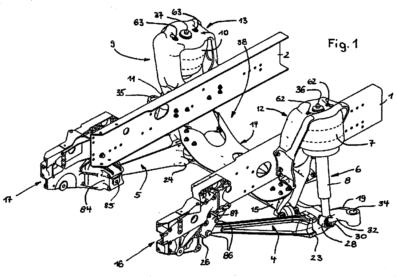
- a front axle is an example of the rigid axle according to the invention shown. From the chassis are in the drawing as parts of the frame whose two side members are labeled 1 and 2.
- the rigid axle shown includes all suspension, suspension and Damping elements from the following main parts, namely a rigid axle body 3, a left trailing arm 4 and right trailing arm 5, a left strut 6 with air or coil spring 7 and this coaxial shock absorber 8, a right Strut 9 with air or coil spring 10 and this coaxial shock absorber 11, a Panhard rod 15 and a - seen from the front - U-shaped cross member 38, which consists of a left strut holder 12, a right strut holder 13 and a crossbar 14 is composed.
- Each of them is outside on one Frame side members 1 and 2 attached and used for frame-side articulation of the rigid axle according to the invention and in the present example also beyond as a holding, supporting and bearing element for a larger number of vehicle parts to be attached.
- the rigid axle according to the invention then brings out its advantages in particular, if - as shown - in the manner of a self-stabilizing torsion beam axle is trained.
- the rigid axle is basically designed that only the Panhard rod 15 is necessary for their transverse guidance and they without the Previously necessary in heavy commercial vehicles to limit swaying U-shaped stabilizer works, but its function is imprinted on a composite is that of the rigid axle body 3 and the two attached to it Trailing arms 4, 5 assembled.
- the rigid axle body 3 obeys in a straight central region 18 between the two trailing arms 4, 5 connected to it are designed to be torsionally defined.
- each has the two equally long trailing arms 4, 5 between his foot 23 and 24 and one other end existing bearing eye 26 or 27 with a rod-shaped area one that changes in size over the length to the bearing eye 26 or 27 decreasing cross-section.
- the two trailing arms 4, 5 to the vehicle longitudinal center axis mirror-symmetrical and - viewed from above - so swept towards each other are connected to the rigid axle body 3 so that they enclose a trapezoidal surface, the distance between their bearing eyes 26 and 27 with which they each the frame-mounted multi-function end shields 16 and 17 articulated are, is smaller than the distance between their axles-side feet 23 and 24. If the rigid axle according to the invention is installed in the vehicle, the two run Trailing arms 4, 5 - viewed from the side - starting from the rigid axle body 3 directed obliquely upwards to the multi-functional position shields 16 on the frame or 17 out.
- each strut 6 and 9 is spatially above and laterally outside of the adjacent frame side member 1 or 2 on one the two strut brackets 12 and 13 supported and attached.
- the two strut holders according to the invention, 12 and 13 form together with the crossbar 14 the - seen from the front - U-shaped cross member 38, the cross member 14th the rigid axle body 3 and the Panhard rod 15 forming a roof at a short distance above bridged and also the two frame side members 1, 2 stabilizing connects with each other.
- the cross member 14 is hat-shaped in cross section Pressed sheet metal part, optionally also forged or cast part, formed a straight central section 39 and on both sides of the same one pulled up obliquely End portion 40 and 41 has.
- a mouth with which the strut holder 12 or 13 to be connected is attacked on the outside.
- Each mouth is cut out by a cutout 42 or 43 in Upper flange of the crossbar 14 and remaining on both sides of each cutout 42 or 43
- Cheeks 44, 45 or 46, 47 formed, which on the respective strut holder 12th or 13 associated front and rear associated contact surfaces 48, 49 or 50, 51 are.
- the cross-member 14 In the area of these contact surfaces 48, 49 and 50, 51, the cross-member 14 is included their cheeks 44, 45 and 46, 47 supported and there by appropriate holes or holes 52 penetrating screws 53 with the respective strut holder 12 or 13 firmly connected. In the middle of his top chord, the crossbar can be 14 have one or more openings for weight reduction.
- the two strut brackets 12 and 13 are preferably each by a steel casting realized that after the casting in the required places is finished or finished.
- Each strut holder 12 or 13 is what his As far as shape is concerned, at least in its upper area in the manner of an exterior open half-shell 54 and 55 formed, from the boundary wall 56th or 57 the associated strut 6 or 9 in the area of its air or coil spring 7 or 10 partially covered radially outside with a small distance from the inside is and on the head plate 58 and 59, the respective strut 6 and 9 at the top supported and by means of two holes 60 or 61 penetrating screw connections 62 or 63 is attached.
- a central hole 64 or 65 in the strut head plate 58 or 59 is used to center the respective shock absorber 12 or 13 and free passage from its upper end 36 or 37.
- Each suspension strut bracket 12 or 13 has a height range on the outside of the half-shell 54 or 55 then a connecting flange 66 or 67 with several Screw holes 68 and 69 on.
- the respective connection flange 66 or 67 which is given approximately in the center of thrust, is each of the two strut holders 12 or 13 flanged to the outside of the associated frame side member 1 or 2 and there in each case by means of a plurality of holes 68 and 69, respectively, which are aligned within the longitudinal member Holes penetrating screws 70 attached with associated nuts.
- Different openings 71 and 72 in the strut holders 12 and 13 serve to reduce their weight.
- One of the two strut holders 12 and 13 is about its actual function
- another function is imprinted, namely that of the support, holding and articulation element to form one end of the Panhard rod 15.
- the shock absorber holder 12 or 13 in question downwards through a bearing plate 73 extended, at the lower end of a mouth and on both sides of it a bearing eye 74 and 75 are formed, on which the Panhard rod 15 has an in supports one end bearing eye 76 built-in claw joint 77 and by means of Screws 78 is attached.
- the Panhard rod 15 is z. B. about a claw joint 80 installed in the bearing eye 79 there at a suitable point of the rigid axle trailing arm assembly.
- a connecting block is fastened to it or molded on, on which a corresponding contact surface and threaded holes for screwing of the claw joint 80 are worked on.
- this is a mouth-like bearing bracket 81 projecting laterally inwards or - As shown - co-molded, the one outer contact surface and two internal blind thread holes for the support of the claw joint 80 and its Has attachment by means of screws 82.
- the one as an essentially straight rod Panhard rod formed with the bearing eyes 76, 79 forged on the end 15 extends due to its articulation as described above approximately parallel or slightly oblique to the central region 18 of the rigid axle body 3 fading.
- the two multifunction end shields 16, 17 each have one towards the center of the vehicle protruding projection 83 or 84, in the interior of which is free from the outside there is a pivot point for the rigid axle, in the form of a contact surface and a transverse bore 85 into which the front trailing arm bearing eye is installed 26 or 27 penetrating bearing bolts installed and then each of these two bearings from the outside by means of several Screws 86 secured to multifunction bearing plate 16 or 17 attached cover 87 becomes.
Landscapes
- Engineering & Computer Science (AREA)
- Mechanical Engineering (AREA)
- Chemical & Material Sciences (AREA)
- Combustion & Propulsion (AREA)
- Transportation (AREA)
- Vehicle Body Suspensions (AREA)
Abstract
Description
- Fig. 1
- perspektivisch den vorderen Endbereich des Fahrgestells eines Frontlenker-Lastkraftwagen (als Beispiel eines schweren Nutzfahrzeuges) mit der erfindungsgemäßen Starrachse samt Aufhängung, Federung und Dämpfung,
- Fig. 2
- den Fahrgestellbereich gemäß Fig. 1 in Ansicht von vorn,
- Fig. 3
- den Fahrgestellbereich gemäß Fig. 1 in Seitenansicht,
- Fig. 4
- die Darstellung gemäß Fig. 2 ohne Federbeine,
- Fig. 5
- die Darstellung gemäß Fig. 1 ohne Federbeine,
- Fig. 6
- die Darstellung gemäß Fig. 3 ohne Federbeine,
- Fig. 7
- die Darstellung gemäß Fig. 4 in Draufsicht ohne Panhardstab,
- Fig. 8
- den Starrachskörper-Längslenker-Verbund aus den Fig. 1 bis 7 in perspektivischer Alleindarstellung,
- Fig. 9
- einen Längslenker aus dem Starrachskörper-Längslenker-Verbund gemäß Fig. 8 in perspektivischer Alleindarstellung,
- Fig. 10
- den erfindungsgemäßen U-förmigen Querträger in vorderansichtiger Alleindarstellung,
- Fig. 11
- den erfindungsgemäßen Querträger in perspektivischer Alleindarstellung,
- Fig. 12 bis 17
- je eine unterschiedliche Ansicht des einen der beiden Federbeinhalter aus dem erfindungsgemäßen Querträger,
- Fig. 18 bis 23
- je eine unterschiedliche Ansicht des anderen der beiden Federbeinhalter aus dem erfindungsgemäßen Querträger.
Claims (12)
- Fahrgestell eines schweren Nutzfahrzeuges, mit einem Rahmen, dessen beide Längsträger (1, 2) über mehrere Querträger miteinander verbunden sind, und mit mehreren Achsen, von denen wenigstens eine eine Starrachse ist, die sich einschließlich ihrer Federung und Aufhängung durch folgende Merkmale kennzeichnet:a) je Achsseite ist ein aus einer Luft- oder Schraubenfeder (7, 10) und einem hierzu koaxialen Stoßdämpfer (8, 11) bestehendes Federbein (6, 9) vorgesehen,b) jedes Federbein (6, 9) ist mit seinem oberen Ende (36, 37) an einem zugehörigen Federbeinhalter (12, 13) und mit seinem unteren Ende (28, 29) an einer Anlenkstelle (32, 33) am Starrachskörper (3) angeschlossen,c) im Bereich der Starrachse sind die beiden Rahmen-Längsträger (1, 2) durch einen - von vorne gesehen - U-förmigen Querträger (38) stabilisierend miteinander verbunden,d) der U-förmige Querträger (38) besteht aus drei Teilen, nämlich einer dachbildend den Starrachskörper (3) und einen zur Starrachs-Querführung dienenden Panhardstab (15) mit geringem Abstand überbrückenden Quertraverse (14) und den beiden, an den Enden der Quertraverse (14) angeschlossenen Federbeinhaltern (12, 13).
- Fahrgestell nach Anspruch 1, dadurch gekennzeichnet, daß die Quertraverse (14) des U-förmigen Querträger (38) durch ein im Querschnitt hutförmiges Blechpreß-, Guß- oder Schmiedeteil gebildet ist, dessen links- und rechtsseitiger Außenbereich nach Art eines Maules ausgebildet ist, in das ein Federbeinhalter (12, 13) mit einem Anschlußbereich eingepaßt und dort mittels mehrerer Schrauben (53) an der Quertraverse (14) befestigt ist.
- Fahrgestell nach einem der vorhergehenden Ansprüche, dadurch gekennzeichnet, daß die Quertraverse (14) des U-förmigen Querträgers (38) einen geraden Mittelabschnitt (39), mit dem sie den Starrachskörper (3) und den Panhardstab (15) mit geringem Abstand überdeckt, und beiderseits des Mittelabschnitts (39) je einen schräg hochgezogenen Endabschnitt (40, 41) aufweist, dessen Ende nach Art eines Maules ausgebildet ist.
- Fahrgestell nach einem der vorhergehenden Ansprüche, dadurch gekennzeichnet, daß jedes zum Anschluß eines Federbeinhalters (12, 13) vorgesehene Maul durch einen endseitigen Ausschnitt (42, 43) im Obergurt der Quertraverse (14) und beiderseits jedes Ausschnitts (42, 43) verbleibende Wangen (44, 45; 46, 47) gebildet ist, denen am jeweiligen Federbeinhalter (12, 13) vorn und hinten zugehörige Anlageflächen (48, 49 bzw. 50, 51) zugeordnet sind, in deren Bereich die Quertraverse (14) mit ihren Wangen (44, 45; 46, 47) abgestützt und dort auch entsprechende Bohrungen bzw. Löcher (52) durchdringende Schrauben (53) mit dem der jeweilige Federbeinhalter (12, 13) fest verbunden ist.
- Fahrgestell nach einem der vorhergehenden Ansprüche, dadurch gekennzeichnet, daß in der Quertraverse (14) und den Federbeinhaltern (12, 13) des U-förmigen Querträgers (38) an geeigneten Stellen zur Gewichtsreduzierung dienende Löcher oder Durchbrüche vorgesehen sind.
- Fahrgestell nach einem der vorhergehenden Ansprüche, dadurch gekennzeichnet, daß einem der beiden Federbeinhalter (12, 13) über seine eigentliche Funktion hinaus noch jene Funktion aufgeprägt ist, nämlich das rahmenfeste Abstütz-, Halte- und Anlenkorgan für das eine Ende des Panhardstabes (15) zu bilden.
- Fahrgestell nach Anspruch 6, dadurch gekennzeichnet, daß einer der beiden Federbeinhalter (12, 13) nach unten durch ein Lagerschild (73) verlängert ist, an dessen unterem Ende ein Maul und beiderseits desselben je ein Lagerauge (74, 75) ausgebildet sind, an denen der Panhardstab (15) über ein in seinem einenendigen Lagerauge (76) eingebautes Pratzengelenk (77) und zugehörige Schrauben (78) befestigt ist.
- Fahrgestell nach einem der Ansprüche 6 und 7, dadurch gekennzeichnet, daß der Panhardstab (15) mit seinem anderen, gegenüberliegenden Ende über ein in das dortige Lagerauge (79) eingebautes Pratzengelenk (80) an geeigneter Stelle des Starrachskörper-Längslenker-Verbundes angelenkt ist.
- Fahrgestell nach Anspruch 8, dadurch gekennzeichnet, daß der Panhardstab (15) über das Pratzengelenk (80) an einem Lagerbock (81) angeschlossen wird, der entweder am Achskörper (3) oder einem der beiden Längslenker (4, 5) entweder mitangeformt oder dort angebaut ist und an dem eine entsprechende Anlagefläche und Gewindebohrungen für die Anschraubung des Pratzengelenkes (80) mittels Schrauben (82) vorgesehen sind.
- Fahrgestell nach einem der vorhergehenden Ansprüche, dadurch gekennzeichnet, daß jeder Federbeinhalter (12, 13) zumindest in seinem oberen Bereich nach Art einer nach außen offenen Halbschale (54, 55) ausgebildet ist, von deren Begrenzungswand (56, 57) das zugehörige Federbein (6, 9) im Bereich seiner Luft- oder Schraubenfeder (7, 10) radial außen mit geringem Abstand von innen her partiell überdeckt wird und an deren Kopfplatte (58, 59) das jeweilige Federbein (6, 9) obenendig abgestützt und mittels je zwei Löcher (60, 61) durchdringenden Verschraubungen (62, 63) befestigt ist, wobei ein Zentralloch (64, 65) in der Federbein-Kopfplatte (58, 59) zur Zentrierung des jeweiligen Federbeines (12, 13) und freien Durchtritt von dessen oberem Ende (36, 37) dient.
- Fahrgestell nach Anspruch 10, dadurch gekennzeichnet, daß jeder Federbeinhalter (12, 13) etwa in seinem mittleren Höhenbereich einen außenseitig an der Halbschale (54, 55) anschließenden Anschlußflansch (66, 67) mit mehreren Schraubenlöchern (68, 69) aufweist, daß dieser Anschlußflansch (66, 67) etwa im Schubmittelpunkt gegeben ist, und daß jeder Federbeinhalter (12, 13) mit seinem Anschlußflansch (66, 67) über die Schraubenlöcher (68, 69) und hierzu längsträgerintern fluchtende Löcher durchdringende Schrauben (70) und zugehörigen Muttern am jeweiligen Rahmen-Längsträger (1, 2) angeflanscht befestigt ist.
- Fahrgestell nach einem oder mehreren der vorhergehenden Ansprüche, dadurch gekennzeichnet, daß die Starrachse nach Art einer selbststabilisierenden Verbundlenkerachse ausgebildet ist, demzufolge die Funktion eines das Wanken des Nutzfahrzeuges begrenzenden Stabilisators einem Bauteilverbund aufgeprägt ist, der aus dem Starrachskörper (3) und zwei fest an diesem angeschlossenen Längslenkern (4, 5) besteht, wobeidie beiden Längslenker (4, 5) weit voneinander beabstandet jeweils stirnseitig vorn oder hinten am Starrachskörper mittels Schrauben (25) kraft- und gegebenenfalls auch formschlüssig angeflanscht sind,der Starrachskörper (3) in einem geraden Mittelbereich (18) zwischen den angeschlossenen Längslenkern (4, 5) definiert torsionsfähig ausgebildet ist,die beiden Längslenker (4, 5) in Vertikalrichtung gesehen vergleichsweise biegesteif, um ihre Längsachse aber begrenzt tordierbar ausgebildet und hinsichtlich ihrer Biegesteifigkeit sowie Torsionsfähigkeit auf den Gesamtstabilisierungseffekt in Verbindung mit dem torsionsfähigen Starrachskörper (3) abgestimmt sind durch entsprechende Bemessung und Formgebung der hierfür maßgeblichen Querschnitte,diese Verbundlenkerachse mit den freien Enden ihrer beiden Längslenker (4, 5) an rahmenfesten Lagerstellen (16, 17) angelenkt ist, unddie je Achsseite eine Anlenkstelle (32, 33) für das untere Ende (28, 29) eines Federbeines (6, 9) am Starrachskörper (3) so weit wie möglich zu einem außenendigen Radträger-Anschlußkopf (34, 35) hingerückt angeordnet ist, daß sich eine größtmögliche Federspur und eine - von vorne gesehen - gepfeilte Anordnung der beiden Federbeine (6, 9) ergibt, bei der die oberen Enden (36, 37) derselben weniger weit voneinander beabstandet sind als deren untere Enden (28, 29).
Applications Claiming Priority (2)
| Application Number | Priority Date | Filing Date | Title |
|---|---|---|---|
| DE19809268A DE19809268A1 (de) | 1998-03-04 | 1998-03-04 | Fahrgestell eines schweren Nutzfahrzeuges |
| DE19809268 | 1998-03-04 |
Publications (2)
| Publication Number | Publication Date |
|---|---|
| EP0940323A1 true EP0940323A1 (de) | 1999-09-08 |
| EP0940323B1 EP0940323B1 (de) | 2003-05-07 |
Family
ID=7859706
Family Applications (1)
| Application Number | Title | Priority Date | Filing Date |
|---|---|---|---|
| EP99101609A Expired - Lifetime EP0940323B1 (de) | 1998-03-04 | 1999-02-03 | Fahrgestell eines schweren Nutzfahrzeuges |
Country Status (2)
| Country | Link |
|---|---|
| EP (1) | EP0940323B1 (de) |
| DE (2) | DE19809268A1 (de) |
Cited By (3)
| Publication number | Priority date | Publication date | Assignee | Title |
|---|---|---|---|---|
| EP2363336A1 (de) * | 2010-03-02 | 2011-09-07 | Iveco Magirus Ag | Chassis eines Frontlenkers mit einem kippbaren Führerhaus |
| US10577024B2 (en) * | 2018-06-25 | 2020-03-03 | Honda Motor Co., Ltd. | Bracket and mounting system for use in supporting a module within a vehicle |
| WO2022060648A1 (en) | 2020-09-17 | 2022-03-24 | Trova Commercial Vehicles Inc | Frame cross member for battery electric vehicle |
Families Citing this family (1)
| Publication number | Priority date | Publication date | Assignee | Title |
|---|---|---|---|---|
| KR100764485B1 (ko) * | 2005-12-12 | 2007-10-08 | 현대자동차주식회사 | 자동차용 서포트 빔 |
Citations (6)
| Publication number | Priority date | Publication date | Assignee | Title |
|---|---|---|---|---|
| US4168086A (en) * | 1977-08-01 | 1979-09-18 | Dana Corporation | Radius arm support for a driving axle |
| DE4226500A1 (de) * | 1992-08-11 | 1994-02-17 | Daimler Benz Ag | Anschlußknoten |
| EP0636531A2 (de) * | 1993-07-27 | 1995-02-01 | Nissan Motor Co., Ltd. | Fahrzeugstruktur |
| EP0678405A2 (de) * | 1994-04-18 | 1995-10-25 | Mercedes-Benz Ag | Omnibus-Steuerkopf mit einem Federbeinträger |
| US5641181A (en) * | 1995-03-23 | 1997-06-24 | Ford Motor Company | Cross member for a vehicle having rack and pinion steering |
| DE19624242A1 (de) * | 1996-06-18 | 1997-09-18 | Daimler Benz Ag | Vorrichtung zur Querführung einer Starrachse eines Kraftfahrzeuges |
Family Cites Families (6)
| Publication number | Priority date | Publication date | Assignee | Title |
|---|---|---|---|---|
| FR1226451A (fr) * | 1959-01-13 | 1960-07-13 | Simca Automobiles Sa | Soubassement pour véhicule automobile |
| US4386792A (en) * | 1978-10-04 | 1983-06-07 | Ford Motor Company | Fabricated load support structural member |
| FR2662118A1 (fr) * | 1990-05-17 | 1991-11-22 | Peugeot | Train arriere d'un vehicule automobile. |
| JP3079791B2 (ja) * | 1992-09-11 | 2000-08-21 | 日産自動車株式会社 | 車両用アクスルビーム式サスペンションの配設構造 |
| US5636857A (en) * | 1995-03-06 | 1997-06-10 | Ford Motor Company | Vehicle solid axle front suspension system |
| DE4329862A1 (de) * | 1993-09-03 | 1995-03-09 | Hotzenblitz Mobile Gmbh Co Kg | Hinterachse für Kraftfahrzeuge |
-
1998
- 1998-03-04 DE DE19809268A patent/DE19809268A1/de not_active Withdrawn
-
1999
- 1999-02-03 DE DE59905387T patent/DE59905387D1/de not_active Expired - Lifetime
- 1999-02-03 EP EP99101609A patent/EP0940323B1/de not_active Expired - Lifetime
Patent Citations (6)
| Publication number | Priority date | Publication date | Assignee | Title |
|---|---|---|---|---|
| US4168086A (en) * | 1977-08-01 | 1979-09-18 | Dana Corporation | Radius arm support for a driving axle |
| DE4226500A1 (de) * | 1992-08-11 | 1994-02-17 | Daimler Benz Ag | Anschlußknoten |
| EP0636531A2 (de) * | 1993-07-27 | 1995-02-01 | Nissan Motor Co., Ltd. | Fahrzeugstruktur |
| EP0678405A2 (de) * | 1994-04-18 | 1995-10-25 | Mercedes-Benz Ag | Omnibus-Steuerkopf mit einem Federbeinträger |
| US5641181A (en) * | 1995-03-23 | 1997-06-24 | Ford Motor Company | Cross member for a vehicle having rack and pinion steering |
| DE19624242A1 (de) * | 1996-06-18 | 1997-09-18 | Daimler Benz Ag | Vorrichtung zur Querführung einer Starrachse eines Kraftfahrzeuges |
Cited By (6)
| Publication number | Priority date | Publication date | Assignee | Title |
|---|---|---|---|---|
| EP2363336A1 (de) * | 2010-03-02 | 2011-09-07 | Iveco Magirus Ag | Chassis eines Frontlenkers mit einem kippbaren Führerhaus |
| WO2011107455A1 (en) * | 2010-03-02 | 2011-09-09 | Iveco Magirus Ag | Chassis of a forward control truck with a tiltable cab |
| CN102811898A (zh) * | 2010-03-02 | 2012-12-05 | 依维柯马基路斯公司 | 具有可倾斜的驾驶室的正向控制卡车的底盘 |
| CN102811898B (zh) * | 2010-03-02 | 2015-09-16 | 依维柯马基路斯公司 | 具有可倾斜的驾驶室的正向控制卡车的底盘 |
| US10577024B2 (en) * | 2018-06-25 | 2020-03-03 | Honda Motor Co., Ltd. | Bracket and mounting system for use in supporting a module within a vehicle |
| WO2022060648A1 (en) | 2020-09-17 | 2022-03-24 | Trova Commercial Vehicles Inc | Frame cross member for battery electric vehicle |
Also Published As
| Publication number | Publication date |
|---|---|
| DE59905387D1 (de) | 2003-06-12 |
| EP0940323B1 (de) | 2003-05-07 |
| DE19809268A1 (de) | 1999-09-09 |
Similar Documents
| Publication | Publication Date | Title |
|---|---|---|
| EP0940272B1 (de) | Fahrgestell eines Frontlenker-Lastkraftwagen | |
| DE102013108695B4 (de) | Hilfsrahmen für eine Kraftfahrzeugachse | |
| EP2155508B1 (de) | Hinterachse für ein kraftfahrzeug | |
| DE102004028161B4 (de) | Unterfahrschutz für Personenkraftfahrzeuge zur Anordnung unter Längsträgerniveau vor einem Hilfsrahmen oder Achsträger als zusätzliche Crashebene | |
| WO2007031060A1 (de) | Vorderachsträger, insbesondere für kraftfahrzeuge | |
| EP1318064B1 (de) | Modular aufgebauter Tragrahmen für ein Nutzfahrzeug | |
| DE102009042060A1 (de) | Strukturbauteil für Hinterrahmenstruktur eines Kraftfahrzeugs | |
| EP0798198B1 (de) | Vordere Lagerung des kippbaren Fahrerhauses eines Lastkraftwagens | |
| EP0940320B1 (de) | Fahrgestell eines schweren Nutzfahrzeuges | |
| EP0940319B1 (de) | Fahrgestell eines schweren Nutzfahrzeuges | |
| WO2014009320A1 (de) | Radaufhängungslenker und achsaggregat für eine nicht angetriebene achse eines fahrzeugs, insbesondere eines nutzfahrzeugs | |
| DE69426991T2 (de) | Längsarmaufhängung | |
| EP2780182B1 (de) | Starrachse mit luftfederung | |
| EP0940324B1 (de) | Fahrgestell eines schweren Nutzfahrzeuges | |
| EP0940322B1 (de) | Fahrgestell eines schweren Nutzfahrzeuges | |
| EP0940325B1 (de) | Fahrgestell eines schweren Nutzfahrzeuges | |
| WO2004048181A1 (de) | Vorderwagenstruktur | |
| EP0940323B1 (de) | Fahrgestell eines schweren Nutzfahrzeuges | |
| EP0940321B1 (de) | Fahrgestell eines schweren Nutzfahrzeuges | |
| DE102015004858A1 (de) | Lenker für Starrachsen von Nutzfahrzeugen | |
| DE202015102551U1 (de) | Achsanordnung | |
| EP1447247B1 (de) | Aufhängung einer Starrachse in einem Fahrzeug | |
| DE102006010130B4 (de) | Hilfsrahmen, insbesondere für Kraftfahrzeuge | |
| DE102018006572B4 (de) | Fahrzeugaufhängungsanordnung für mindestens eine Radachse | |
| EP4261112A1 (de) | Achsträger-struktur und achsträger derselben sowie herstellungs- und montage-verfahren dafür |
Legal Events
| Date | Code | Title | Description |
|---|---|---|---|
| PUAI | Public reference made under article 153(3) epc to a published international application that has entered the european phase |
Free format text: ORIGINAL CODE: 0009012 |
|
| 17P | Request for examination filed |
Effective date: 19990714 |
|
| AK | Designated contracting states |
Kind code of ref document: A1 Designated state(s): DE FR IT NL SE |
|
| AX | Request for extension of the european patent |
Free format text: AL;LT;LV;MK;RO;SI |
|
| AKX | Designation fees paid |
Free format text: DE FR IT NL SE |
|
| 17Q | First examination report despatched |
Effective date: 20010716 |
|
| GRAG | Despatch of communication of intention to grant |
Free format text: ORIGINAL CODE: EPIDOS AGRA |
|
| GRAG | Despatch of communication of intention to grant |
Free format text: ORIGINAL CODE: EPIDOS AGRA |
|
| GRAH | Despatch of communication of intention to grant a patent |
Free format text: ORIGINAL CODE: EPIDOS IGRA |
|
| GRAH | Despatch of communication of intention to grant a patent |
Free format text: ORIGINAL CODE: EPIDOS IGRA |
|
| GRAA | (expected) grant |
Free format text: ORIGINAL CODE: 0009210 |
|
| AK | Designated contracting states |
Designated state(s): DE FR IT NL SE |
|
| REF | Corresponds to: |
Ref document number: 59905387 Country of ref document: DE Date of ref document: 20030612 Kind code of ref document: P |
|
| REG | Reference to a national code |
Ref country code: SE Ref legal event code: TRGR |
|
| ET | Fr: translation filed | ||
| PLBE | No opposition filed within time limit |
Free format text: ORIGINAL CODE: 0009261 |
|
| STAA | Information on the status of an ep patent application or granted ep patent |
Free format text: STATUS: NO OPPOSITION FILED WITHIN TIME LIMIT |
|
| 26N | No opposition filed |
Effective date: 20040210 |
|
| REG | Reference to a national code |
Ref country code: NL Ref legal event code: TD Effective date: 20110420 |
|
| REG | Reference to a national code |
Ref country code: FR Ref legal event code: CD |
|
| REG | Reference to a national code |
Ref country code: DE Ref legal event code: R081 Ref document number: 59905387 Country of ref document: DE Owner name: MAN TRUCK & BUS AG, DE Free format text: FORMER OWNER: MAN NUTZFAHRZEUGE AG, 80995 MUENCHEN, DE Effective date: 20110518 |
|
| REG | Reference to a national code |
Ref country code: FR Ref legal event code: PLFP Year of fee payment: 18 |
|
| REG | Reference to a national code |
Ref country code: FR Ref legal event code: PLFP Year of fee payment: 19 |
|
| REG | Reference to a national code |
Ref country code: FR Ref legal event code: PLFP Year of fee payment: 20 |
|
| PGFP | Annual fee paid to national office [announced via postgrant information from national office to epo] |
Ref country code: NL Payment date: 20180223 Year of fee payment: 20 |
|
| PGFP | Annual fee paid to national office [announced via postgrant information from national office to epo] |
Ref country code: SE Payment date: 20180227 Year of fee payment: 20 Ref country code: IT Payment date: 20180221 Year of fee payment: 20 Ref country code: FR Payment date: 20180227 Year of fee payment: 20 |
|
| PGFP | Annual fee paid to national office [announced via postgrant information from national office to epo] |
Ref country code: DE Payment date: 20180430 Year of fee payment: 20 |
|
| REG | Reference to a national code |
Ref country code: DE Ref legal event code: R071 Ref document number: 59905387 Country of ref document: DE |
|
| REG | Reference to a national code |
Ref country code: NL Ref legal event code: MK Effective date: 20190202 |
|
| REG | Reference to a national code |
Ref country code: SE Ref legal event code: EUG |