EP0940332A2 - Véhicule à deux roues, en particulier bicyclette - Google Patents
Véhicule à deux roues, en particulier bicyclette Download PDFInfo
- Publication number
- EP0940332A2 EP0940332A2 EP99103824A EP99103824A EP0940332A2 EP 0940332 A2 EP0940332 A2 EP 0940332A2 EP 99103824 A EP99103824 A EP 99103824A EP 99103824 A EP99103824 A EP 99103824A EP 0940332 A2 EP0940332 A2 EP 0940332A2
- Authority
- EP
- European Patent Office
- Prior art keywords
- tube
- rod
- suspension
- vehicle according
- frame
- Prior art date
- Legal status (The legal status is an assumption and is not a legal conclusion. Google has not performed a legal analysis and makes no representation as to the accuracy of the status listed.)
- Withdrawn
Links
Images


Classifications
-
- B—PERFORMING OPERATIONS; TRANSPORTING
- B62—LAND VEHICLES FOR TRAVELLING OTHERWISE THAN ON RAILS
- B62K—CYCLES; CYCLE FRAMES; CYCLE STEERING DEVICES; RIDER-OPERATED TERMINAL CONTROLS SPECIALLY ADAPTED FOR CYCLES; CYCLE AXLE SUSPENSIONS; CYCLE SIDECARS, FORECARS, OR THE LIKE
- B62K25/00—Axle suspensions
- B62K25/04—Axle suspensions for mounting axles resiliently on cycle frame or fork
- B62K25/06—Axle suspensions for mounting axles resiliently on cycle frame or fork with telescopic fork, e.g. including auxiliary rocking arms
- B62K25/08—Axle suspensions for mounting axles resiliently on cycle frame or fork with telescopic fork, e.g. including auxiliary rocking arms for front wheel
-
- B—PERFORMING OPERATIONS; TRANSPORTING
- B62—LAND VEHICLES FOR TRAVELLING OTHERWISE THAN ON RAILS
- B62K—CYCLES; CYCLE FRAMES; CYCLE STEERING DEVICES; RIDER-OPERATED TERMINAL CONTROLS SPECIALLY ADAPTED FOR CYCLES; CYCLE AXLE SUSPENSIONS; CYCLE SIDECARS, FORECARS, OR THE LIKE
- B62K25/00—Axle suspensions
- B62K25/04—Axle suspensions for mounting axles resiliently on cycle frame or fork
- B62K25/06—Axle suspensions for mounting axles resiliently on cycle frame or fork with telescopic fork, e.g. including auxiliary rocking arms
- B62K25/10—Axle suspensions for mounting axles resiliently on cycle frame or fork with telescopic fork, e.g. including auxiliary rocking arms for rear wheel
Definitions
- the invention relates to a two-wheel vehicle, in particular a bicycle, according to the preamble of claim 1.
- rear-wheel suspension In conventional two-wheelers, rear-wheel suspension is usually made up of one to four joints Connections used.
- the disadvantage of these joint systems is that they ever are complex and susceptible to wear after execution.
- Telescopic suspension forks with tubes sliding into each other are known.
- These telescopic spring forks disadvantageously require large wheel axles and tube diameters depending on the version as well as additional cross connections (so-called boosters) to compensate for Torsional forces.
- the luggage rack is difficult to arrange.
- the object of the invention is to create an improved wheel suspension for the resilient mounting of an impeller of a two-wheeled vehicle, in particular a bicycle.
- the basic idea of the wheel suspension according to the invention for the resilient mounting of a Impeller is that the tube is not as with the common telescopic spring forks is closed at the bottom (so that a spring between the tube sheet and the piston rod is protected), but that according to the invention the tube is open at the bottom, so that the rod can protrude as a continuous tube.
- the spring system is extremely low-wear and stable and particularly suitable as a city or touring or everyday bike.
- the tube of the suspension can form part of the frame or the steering fork or the actual one Frame or be arranged on the actual steering fork.
- the tube is fixed to the steering fork or frame.
- a resilient connection of the tube to the frame is also conceivable.
- Such a slightly elastic attachment of the tube of the rear wheel suspension is reduced the risk of damage to the elements sliding into one another (pipe, rod) strong bumps.
- Claim 3 proposes a constructive implementation.
- the basic principle is in the double pipe system consisting of the outer pipe and the inner rod pipe to arrange the spring element. This results in a very compact and space-saving Construction.
- the spring element is protected inside the tube and is above it not visible, so that this results in a positive overall optical impression.
- the spring element can be a helical spring which is between a Bottom of the rod tube and the outer tube is supported. Can instead of the floor also a suspension device for the spring element located in the rod tube be used.
- a frame part can serve as the upper support point for the spring element or especially the luggage rack.
- Spring elements conceivable instead of the aforementioned helical spring.
- the development according to claim 5 relates to an alternative constructive implementation for the arrangement of the spring element.
- the basic idea here is the spring element in the Arrange outside.
- a cylinder / piston unit can be used as the spring element be used. This can be dimensioned large and extends in the Usually parallel to the tube of the suspension.
- the cylinder / piston unit can be between the tube itself or between the frame (including a luggage rack) and be supported on the rod. This also applies to the front wheel suspension, where the cylinder / piston unit either acts directly on the pipe or on an element the steering fork.
- a coil spring or a rubber or elastomeric buffer may be provided which concentrically surrounds the rod.
- the advantage of the development of claim 7 is that the wheel axle is fixed inside the rod, i.e. at the bottom of the inner rod, which in particular is designed as a rod tube, the receptacle is inserted into the rod. Thereby the wheel axle is just below the lower end of the inner rod. In order to overall, the travel can be better used, as it is just over the wheel axis goes.
- the wheel axle mount advantageously extends to just above the lower edge of the outer tube. This can reinforce the inner bar.
- the guide part in the drive chain can be a point above the bottom bracket for example, trade between the smallest and the largest chainring. Farther a deflection pinion or deflection tube, via which the upper, power-transmitting strand of the chain or toothed belt runs.
- the guide part be defined by an additional gearbox, here the driving force from the bottom bracket is transmitted to the rear wheel axle via this additional gear.
- the development according to claim 10 has the advantage that the suspension with the two movable rods has great internal stability because the spring areas on the left and are connected on the right.
- To create the bridge between the two poles step out of their outer tubes at the top.
- the outer tubes have a slot in its longitudinal extent through which the connecting bridge attack the inner poles.
- the development according to claim 11 has the advantage that the wheel suspension if necessary can be turned off so that the bike is then without suspension.
- the suspension has a damping element assigned.
- the spring effect is evened out for the damping element.
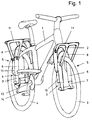
- FIGS. 1 and 2 has a frame 1 with a front steering fork 2. Both the front wheel 3 and the rear wheel 4 have a suspension 5, which in the Embodiment of FIGS. 1 and 2 are identical in principle.
- the suspension 5 of the rear wheel 4 has an approximately vertical tube 6, soft one Forms part of the frame 1. Within the tube 6 there is a longitudinally displaceable Rod 7. Since a suspension 5 is provided on both sides of the rear wheel 4 and therefore two tubes 6 and two rods 7 are also provided, these are two Rods 7 between their upper ends protruding from the tubes 6 rigidly connected to each other by a bridge 8. The two rods 7 and the bridge 8 together form an inverted "U".
- a cylinder / piston unit as a spring element 9 10 arranged. It is also located at the bottom of the rod 7 the axle A of the rear wheel 4.
- a luggage rack 11 is arranged between the frame 1 and the tube 6.
- the suspension of the front wheel 3 is designed accordingly.
- a tube 6 on both sides in which the two rods 7 are guided.
- the two rods 7 are connected to each other by a bridge 8.
- spring element 9 a cylinder / piston unit 10 is also used here.
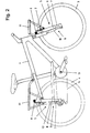
- FIG. 3 differs from the embodiment of FIGS. 1 and 2 in that an additional locking device 12 is provided, which the Rod 7 with respect to the tube 6 and thus the suspension blocked.
- This locking device 12 is indicated schematically in FIG. 3.
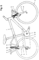
- FIG. 4 does not explicitly show the spring element 9.
- This can, for example be arranged within the tube 6.
- the two positions are shown the A axis in the sprung state (bottom) and in the sprung state (above).
- a point P is shown in the area of the bottom bracket 13, whereby the point P between the largest and the smallest chainring above this bottom bracket 13 is located.
- the distance from the bottom bracket center is less than 20 cm. Most of all the distance of this point P from the two spring positions of the axis A essentially the same size, so that drive influences during the suspension process are largely avoided become.
- the variant in FIG. 5 additionally has the drive chain 14 in the region of the upper run a deflection gear 15, which defines the aforementioned point P in this case. Also here the distances between point P and the two spring positions of axis A are essentially equal.
- the further variant in Fig. 6 has an additional gear 16, which the aforementioned Point P defined. Since, just as in the embodiment variant in FIG. 5, the point P is relative is far up, the tube 6 is slightly inclined with respect to the vertical, so that thereby result in improved spring properties.
- the embodiment in FIG. 7 has a rubber or elastomer buffer as spring element 9 17 on which between the lower end of the tube 6 and the lower end of the Rod 7 is supported.
- the tube 6 is resiliently arranged on the frame 1.
- a slightly deformable sleeve 18 is provided according to FIG. 7b a fastening screw 19 is protruded.
- FIG. 8 shows a spring element 9, which is located within a bellows 25 and is supported between the rack 11 and the rod 7 and is wholly or partly in the rod 7.
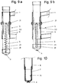
- FIGS. 9a and b show a preferred embodiment in a partial representation of the spring element 9.
- a coil spring 20 serves as spring element 9, which is supported between the tube 6 and the rod 7, the rod in this variant 7 is designed as a tube.
- A serves as a suspension device 21 for the helical spring 20 Cross strut inside the tube 6.
- the rod 7 has an in Movement direction extending slot 22, which is at least the travel corresponds.
- the Coil spring 20 supported on an inner rod 23.
- Fig. 9b shows in comparison to Fig. 9a the compression process, in particular it can be seen that the rod 7 along the Slit 22 moves on the suspension device 21.
- Fig. 10 shows the lower end of a rod 7, which is also a tube is trained.
- a support member 24 for the axis A of Wheel 3, 4 fitted.
- the support element 24 extends to the bottom End of the tube 6 and in this way reinforces the protruding from the bottom of the tube Section of rod 7.
Landscapes
- Engineering & Computer Science (AREA)
- Mechanical Engineering (AREA)
- Axle Suspensions And Sidecars For Cycles (AREA)
- Vehicle Body Suspensions (AREA)
- Automatic Cycles, And Cycles In General (AREA)
- Steering Devices For Bicycles And Motorcycles (AREA)
Applications Claiming Priority (2)
| Application Number | Priority Date | Filing Date | Title |
|---|---|---|---|
| DE29803744U | 1998-03-04 | ||
| DE29803744U DE29803744U1 (de) | 1998-03-04 | 1998-03-04 | Zweiradfederung mit ineinander gleitenden Rohren |
Publications (2)
| Publication Number | Publication Date |
|---|---|
| EP0940332A2 true EP0940332A2 (fr) | 1999-09-08 |
| EP0940332A3 EP0940332A3 (fr) | 2001-06-13 |
Family
ID=8053527
Family Applications (1)
| Application Number | Title | Priority Date | Filing Date |
|---|---|---|---|
| EP99103824A Withdrawn EP0940332A3 (fr) | 1998-03-04 | 1999-02-27 | Véhicule à deux roues, en particulier bicyclette |
Country Status (2)
| Country | Link |
|---|---|
| EP (1) | EP0940332A3 (fr) |
| DE (1) | DE29803744U1 (fr) |
Cited By (3)
| Publication number | Priority date | Publication date | Assignee | Title |
|---|---|---|---|---|
| WO2002004284A1 (fr) * | 2000-06-30 | 2002-01-17 | Lauke, Matthias | Fourche suspendue |
| WO2006012865A1 (fr) * | 2004-08-05 | 2006-02-09 | Klaus Kramer | Suspension pour roue avant de bicyclette |
| KR100819725B1 (ko) | 2007-02-28 | 2008-04-11 | 김효인 | 자전거의 짐받이 완충장치 및 이를 구비한 자전거. |
Families Citing this family (1)
| Publication number | Priority date | Publication date | Assignee | Title |
|---|---|---|---|---|
| GB2497785A (en) * | 2011-12-20 | 2013-06-26 | Aston Martin Lagonda Ltd | Bicycle with rear suspension |
Family Cites Families (11)
| Publication number | Priority date | Publication date | Assignee | Title |
|---|---|---|---|---|
| GB151326A (en) * | 1919-06-17 | 1920-09-17 | David Levy | Improvements relating to shock absorbing devices applicable to motor vehicles, motorcycles, side cars and the like |
| GB223559A (en) * | 1923-10-18 | 1925-03-12 | Abel Mohin | Elastic suspension for the rear fork of a bicycle |
| FR852609A (fr) * | 1938-04-05 | 1940-02-28 | Dispositif élastique de suspension à éléments coulissants et appui pour le cadred'une motocyclette ou analogue | |
| GB645665A (en) * | 1948-10-13 | 1950-11-08 | George Pittman Coleman | Improvements in spring forks for the front spring wheels of motor cycles or the like |
| FR1022088A (fr) * | 1950-07-17 | 1953-02-27 | Fourche élastique avant | |
| FR1031975A (fr) * | 1951-02-02 | 1953-06-29 | Suspensions pour roues avant et arrière de bicyclette | |
| DE911464C (de) * | 1951-06-12 | 1954-05-13 | August Waechter | Teleskop-Vorder- und -Hinterradfederung fuer Fahrraeder |
| CH304928A (de) * | 1951-10-22 | 1955-01-31 | Kreidler Alfred | Teleskopvorderradgabel, deren Gleitrohre auf durch Stege mit dem Steuerrohr starr verbundenen Standrohren geführt sind. |
| US5044648A (en) * | 1989-04-18 | 1991-09-03 | Knapp Thomas D | Bicycle suspension system |
| US5413368A (en) * | 1993-09-16 | 1995-05-09 | Cannondale Corporation | Bicycle with trailing arm wheel suspensions |
| US5671936A (en) * | 1995-08-10 | 1997-09-30 | Turner; David Roy | Shock absorbing bicycle frame apparatus |
-
1998
- 1998-03-04 DE DE29803744U patent/DE29803744U1/de not_active Expired - Lifetime
-
1999
- 1999-02-27 EP EP99103824A patent/EP0940332A3/fr not_active Withdrawn
Non-Patent Citations (1)
| Title |
|---|
| None |
Cited By (3)
| Publication number | Priority date | Publication date | Assignee | Title |
|---|---|---|---|---|
| WO2002004284A1 (fr) * | 2000-06-30 | 2002-01-17 | Lauke, Matthias | Fourche suspendue |
| WO2006012865A1 (fr) * | 2004-08-05 | 2006-02-09 | Klaus Kramer | Suspension pour roue avant de bicyclette |
| KR100819725B1 (ko) | 2007-02-28 | 2008-04-11 | 김효인 | 자전거의 짐받이 완충장치 및 이를 구비한 자전거. |
Also Published As
| Publication number | Publication date |
|---|---|
| EP0940332A3 (fr) | 2001-06-13 |
| DE29803744U1 (de) | 1999-07-01 |
Similar Documents
| Publication | Publication Date | Title |
|---|---|---|
| EP2001733B1 (fr) | Motocyclette avec suspension de roue avant | |
| DE102006062889B4 (de) | Hilfsrahmen, insbesondere für Kraftfahrzeuge | |
| DE19629559B4 (de) | Fahrradrahmen | |
| DE7835967U1 (de) | Kettenantrieb fuer schwingarmgelagerte hinterraeder von motorraedern | |
| WO1995013207A1 (fr) | Dispositif de guidage de roue a suspension sur le cadre d'une bicyclette | |
| DE102015016764A1 (de) | Fahrradgabelschaft mit variabler Steifigkeit | |
| EP2052957A2 (fr) | Cadre de bicyclette | |
| DE102015223280A1 (de) | Achse eines Kraftfahrzeugs mit einer im Achsträger aufgehängten elektromotorischen Antriebseinheit | |
| EP1238900B1 (fr) | Cadre de bicyclette | |
| DE69912562T2 (de) | Aufhängungssystem mit einer starren Pendelachse, insbesondere für Schlepper | |
| AT507144B1 (de) | Tretkurbelantrieb | |
| DE9405076U1 (de) | Gefedertes Fahrrad | |
| EP0899133B1 (fr) | Suspension à roue indépendante pour un essieu arrière | |
| DE102014003625A1 (de) | Hinterrad-Schwinge für ein Fahrrad | |
| EP0940332A2 (fr) | Véhicule à deux roues, en particulier bicyclette | |
| DE4435481A1 (de) | Vorderradaufhängung für Motor- und Fahrräder | |
| EP1399358B1 (fr) | Cadre de bicyclette | |
| DE10008525A1 (de) | Steuerungssystem zur Längsführung von Teleskopwellen und/oder Baugruppen mit Sicherheitsmechanismen in Lenksäulen | |
| DE102017211672A1 (de) | Verstelleinrichtung für ein Fahrwerk eines Kraftfahrzeuges sowie Hinterachslenkung | |
| DE1505720A1 (de) | Aufhaengung eines Hilfsrahmens am Hautprahmen eines Fahrzeuges,insbesondere eines Kraftfahrzeuges | |
| EP3094545B1 (fr) | Ensemble de découplage d'un moteur vis-à-vis de vibrations pour véhicules motorisés à deux roues comprenant une bielle d'ensemble de propulsion | |
| EP1386821B1 (fr) | Direction pour véhicules | |
| EP0387382B1 (fr) | Dispositif de manivelle pour bicyclette, tricycle ou similaire | |
| DE102007003621A1 (de) | Schaltbarer Stabilisator | |
| DE20112448U1 (de) | Fahrradrahmen |
Legal Events
| Date | Code | Title | Description |
|---|---|---|---|
| PUAI | Public reference made under article 153(3) epc to a published international application that has entered the european phase |
Free format text: ORIGINAL CODE: 0009012 |
|
| AK | Designated contracting states |
Kind code of ref document: A2 Designated state(s): AT BE CH DE DK ES FR GB IT LI LU NL SE |
|
| AX | Request for extension of the european patent |
Free format text: AL;LT;LV;MK;RO;SI |
|
| PUAL | Search report despatched |
Free format text: ORIGINAL CODE: 0009013 |
|
| AK | Designated contracting states |
Kind code of ref document: A3 Designated state(s): AT BE CH CY DE DK ES FI FR GB GR IE IT LI LU MC NL PT SE |
|
| AX | Request for extension of the european patent |
Free format text: AL;LT;LV;MK;RO;SI |
|
| 17P | Request for examination filed |
Effective date: 20011208 |
|
| AKX | Designation fees paid |
Free format text: AT BE CH DE DK ES FR GB IT LI LU NL SE |
|
| 17Q | First examination report despatched |
Effective date: 20040414 |
|
| RAP1 | Party data changed (applicant data changed or rights of an application transferred) |
Owner name: KRAMER, KLAUS |
|
| RIN1 | Information on inventor provided before grant (corrected) |
Inventor name: KRAMER, KLAUS |
|
| 17Q | First examination report despatched |
Effective date: 20040414 |
|
| STAA | Information on the status of an ep patent application or granted ep patent |
Free format text: STATUS: THE APPLICATION IS DEEMED TO BE WITHDRAWN |
|
| 18D | Application deemed to be withdrawn |
Effective date: 20070130 |