EP0940355A1 - Stapelsäule zur Aufnahme einer Vielzahl von flächigen Werkstücken - Google Patents
Stapelsäule zur Aufnahme einer Vielzahl von flächigen Werkstücken Download PDFInfo
- Publication number
- EP0940355A1 EP0940355A1 EP98113856A EP98113856A EP0940355A1 EP 0940355 A1 EP0940355 A1 EP 0940355A1 EP 98113856 A EP98113856 A EP 98113856A EP 98113856 A EP98113856 A EP 98113856A EP 0940355 A1 EP0940355 A1 EP 0940355A1
- Authority
- EP
- European Patent Office
- Prior art keywords
- pawl
- stacking column
- column according
- pawls
- workpiece
- Prior art date
- Legal status (The legal status is an assumption and is not a legal conclusion. Google has not performed a legal analysis and makes no representation as to the accuracy of the status listed.)
- Granted
Links
Images


Classifications
-
- B—PERFORMING OPERATIONS; TRANSPORTING
- B65—CONVEYING; PACKING; STORING; HANDLING THIN OR FILAMENTARY MATERIAL
- B65G—TRANSPORT OR STORAGE DEVICES, e.g. CONVEYORS FOR LOADING OR TIPPING, SHOP CONVEYOR SYSTEMS OR PNEUMATIC TUBE CONVEYORS
- B65G1/00—Storing articles, individually or in orderly arrangement, in warehouses or magazines
- B65G1/02—Storage devices
- B65G1/14—Stack holders or separators
Definitions
- the invention relates to a stacking column for receiving a variety of flat workpieces.
- the object of the present invention is a device to create a separate locking of the Workpieces made possible by and for loading and unloading Robot is suitable.
- This task is solved with a stacking column a variety of pawls that move in pawl bearings are arranged in a frame and each have a workpiece stop, with individually triggerable Locking bolts that lock the pawls individually lock their position holding the workpiece, and with erection means for erecting one for inclusion of a workpiece requires the next pawl.
- the erection means are in the form of a control curve and a hammer head on the pawls, wherein the previous jack by its upright movement the following jack is moved to the Habacht position.
- the control curves are arranged one behind the other. The workpiece is loaded during loading slid over the top edge of the frame, with the pawl through the contact of the workpiece with the Workpiece stop from the Habacht position to the erected one Position is moved.
- the locking bolts are independent of one another Bolt shaft mounted.
- the bolt shaft has release cams on through which all locking bolts be moved centrally from their locking position can. With an unlocking lever it is possible to the bolt shaft to rotate, thereby locking bolts out of their locked position.
- the highest functionality of the device according to the invention is given with a horizontal alignment. However, a lateral adjustment in the angle of rotation possible from 90 ° to 45 °.
- a stroke curve By changing the control curve to a stroke curve is the functionality in the area given from 0 ° to 45 °.
- the locking mechanism remains identical in this version.
- the moving parts such as support, control cam, jack bolt, Bolts and unlocking camshaft preferably made of stainless steel.
- the stacking column 10 shown in FIG. 1 exists essentially from a preferably U-shaped Carrier as a frame 21, the frame end plates 22 is limited. Within the frame 21 are a plurality of pawls 16, 16a and 16b Pawl bearings 20 are rotatably arranged.
- the pawls 16, 16a and 16b have workpiece stops 19 on which for example, deep-drawn, pressed, stamped or prefabricated, flat workpieces in any other way 23 concerns.
- the flat workpieces 23 are aligned for transport and fixed by the workpiece stops 19. Tilt the stacking column 10 horizontally the pawls 16, 16a and 16b due to their weight distribution Forward. This is the top edge the pawls 16 below the contact edge 24 of the Frame 21.
- the pawls 16, 16a and 16b by - not shown - springs in the lying position moves. This makes it possible the stacking column also in the vertical arrangement use.
- Each pawl 16, 16a and 16b has a cam 17 and a hammer head 18 with which the alignment the neighboring jack is affected.
- the hammer head 18 presses the latch 16a into the watchful position as soon as the previous pawl 16b through a workpiece 23 in the upright position has been pushed.
- the pawl 16b Hammer head 18 around the pawl bearing 20 of the following Pawl 16a guided to the pawl 16a by pressure on the lower workpiece stop 19.
- the angle of rotation of the first pawl 16a is determined by a Pawl stop 27 limited so that this is at the beginning is also in the watchful position without workpiece 23.
- FIG. 2 shows a pawl 16a in the watchful position.
- the Pawl 16b has been erected by workpiece 23, preferably by a robot over the contact edge 24 of the frame 21 in the direction of the pawl 16b can be pushed.
- the pawl 16b in the erected position rotated.
- the locking bolt 11a is first raised to then due to its weight distribution along the Workpiece back 19 to fall in front of the pawl 16b.
- the locking bolt 11a thus prevents the pawl 16b in the Habacht position or in the lying position Position falls back.
- the locking bolt 11a by a spring pressed into the locking position in front of the pawl 16b. This creates the identical functionality granted without the horizontal position of the stacking column 10 to be dependent.
- the locking bolts 11 and 11a are on a bolt shaft 12 stored, which extends over the entire length of the Frame 21 extends.
- On the bolt shaft 12 are in Storage area of pawls 16, 16a and 16b release cams 13 arranged the latched pawls 16b by rotating the pin shaft 12. The fixation the pawl 16b is thus canceled.
- the bolt shaft 12 is mounted in pin shaft bearings 25 which are connected to the frame 21.
- the pin shaft 12 has at least one of its ends a release lever 14 on. By turning the unlocking lever 14, the Locking bolts 11a are raised.
- Figures 3a, 3b 3c and 3d show a possible embodiment the handle 16.
- the hammer head 18 with the corresponding control curve 17 is L-shaped with the Workpiece stop 19 connected. This is what happens Pawl bearing 20 through the intersection of the two L-legs.
- the hammer head 18 Due to the massive design of the hammer head 18 tends the workpiece stop 19 with a rotatable bearing downward. As FIGS. 3a and 3b show, the hammer head 18 preferably offset with the workpiece stop 19 connected. Here are the hammer heads 18 alternately to the right of section A-A and to the left of Section B-B arranged so that the mutually lifting Do not collide pawls 16b and 16a.
- control curves in a row with another Form design arranged are the control curves in a row with another Form design arranged.
- the workpiece stops 19 are shaped differently. With high flat workpieces 23 are the Workpiece stops 19 also formed higher.
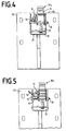
- Figures 4 and 5 show the staggered arrangement of the Hammer head 18 and the control curve 17. Furthermore, the U-shaped design of the frame 21 can be seen, the limited on one side by a frame end plate 22 is.
- the frame end plate 22 is preferably used for fastening the stacking column 10 within a - not shown - transport containers.
- Figure 5 shows the unlocking lever 14, which is in one piece is connected to the pin shaft 12.
- the locking bolt 11a moved to the upright position.
- the locking bolts are immediately back in watchful position to lock the pawls 16a, 16b and 16.
- the pawls 16b are thereby released and fall into the lying position.
- FIG. 6 shows a top view of the stacking column 10. It can be seen that the pin shaft bearing 25 on both ends are arranged within the frame 21. Furthermore, each pawl 16 is assigned a pawl shaft 26, which is within the frame on the right Angle to section A-A from one side of frame 21 extend to others. Are on these jack shafts 26 the pawls 16 are movably arranged by the pawl bearings 20.
Landscapes
- Engineering & Computer Science (AREA)
- Mechanical Engineering (AREA)
- Stacking Of Articles And Auxiliary Devices (AREA)
- Stackable Containers (AREA)
Abstract
Description
- Figur 1
- zeigt einen Ausschnitt der Seitenansicht einer Stapelsäule, mit einem Rahmen, der von einer Rahmenabschlußplatte begrenzt ist, mit einer Vielzahl von Klinken, die innerhalb des Rahmens angeordnet sind und von denen eine in Habacht-Position gehalten wird, mit Verriegelungsbolzen, die auf einer Bolzenwelle gelagert sind, und mit Entriegelungsnocken, die auf der Bolzenwelle angeordnet sind, um die Verriegelung aufzuheben;
- Figur 2
- zeigt einen Ausschnitt der Seitenansicht einer Stapelsäule nach Figur 1, wobei sich eine Klinke in aufgerichteter Position befindet und ein Werkstück stützt, wodurch eine weitere Klinke in Habacht-Position bewegt worden ist;
- Figuren 3a, 3b, 3c und 3d
- zeigen unterschiedliche Ansichten der Klinke, mit einer Steuerkurve, mit einem Hammerkopf, mit einem Werkstückanschlag und mit einem Klinkenlager;
- Figur 4
- zeigt die Vorderansicht einer Stapelsäule nach Figur 1, mit einer Rahmenabschlußplatte, mit einer Klinke in Habacht-Position, deren Verriegelungsbolzen sich nicht in der Verriegelungsposition befindet;
- Figur 5
- zeigt die Vorderansicht der Stapelsäule nach Figur 4, mit einem Entriegelungshebel, der auf die Bolzenwelle wirkt;
- Figur 6
- zeigt einen Ausschnitt der Draufsicht auf eine Stapelsäule nach Figur 1, ohne zweite Rahmenabschlußplatte.
- 10
- Stapelsäule
- 11
- Verriegelungsbolzen
- 11a
- Verriegelungsbolzen in Verriegelungsposition
- 12
- Bolzenwelle
- 13
- Entriegelungsnocke
- 14
- Entriegelungshebel
- 15
- Wellenlager
- 16
- Klinke in liegender Position
- 16a
- Klinke in Habacht-Position
- 16b
- Klinke in aufgerichteter Position
- 17
- Steuerkurve
- 18
- Hammerkopf
- 19
- Werkstückanschlag
- 20
- Klinkenlager
- 21
- Rahmen
- 22
- Rahmenabschlußplatte
- 23
- Werkstück
- 24
- Auflagekante
- 25
- Bolzenwellenlager
- 26
- Klinkenwelle
- 27
- Klinkenanschlag
Claims (10)
- Stapelsäule zur Aufnahme einer Vielzahl von flächigen Werkstücken,mit einer Vielzahl von Klinken (16, 16a, 16b), die in Klinkenlagern (20) beweglich in einem Rahmen (21) angeordnet sind und die jeweils einen Werkstückanschlag (19) aufweisen,mit einzeln auslösbaren Verriegelungsbolzen (11, 11a), die die Klinken (16) einzeln in ihrer das Werkstück (23) haltenden Position arretieren, undmit Aufrichtmitteln (17, 18) zum Aufrichten einer zur Aufnahme eines Werkstücks (23) benötigten nächsten Klinke (16a).
- Stapelsäule nach Anspruch 1, dadurch gekennzeichnet, daß die Aufrichtmittel in Form einer Steuerkurve (17) und eines Hammerkopfs (18) an den Klinken (16, 16a, 16b) ausgebildet sind, wobei eine vorhergehende Klinke (16b) durch eine ihr in Aufrichtrichtung nachfolgende Klinke (16a) in eine Habacht-Position bewegbar ist.
- Stapelsäule nach den Ansprüchen 1 und 2, dadurch gekennzeichnet, daß der Hammerkopf (18) und die Steuerkurve (17) abwechselnd versetzt hintereinander an den Klinken (16a, 16b) angeordnet sind.
- Stapelsäule nach den Ansprüchen 1 bis 3, dadurch gekennzeichnet, daß jeder Klinke (16, 16a, 16b) ein Verriegelungsbolzen (11, 11a) zugeordnet ist und die Verriegelungsbolzen (11, 11a) unabhängig voneinander auf einer Bolzenwelle (12) beweglich gelagert sind.
- Stapelsäule nach den Ansprüchen 1 bis 4, dadurch gekennzeichnet, daß die Bolzenwelle (12) Entriegelungsnocken (13) aufweist und alle Verriegelungsbolzen (11, 11a) durch die Entriegelungsnocken (13) aus ihrer Verriegelungsposition bewegbar sind.
- Stapelsäule nach den Ansprüchen 1 bis 5, dadurch gekennzeichnet, daß die Bolzenwelle (12) mit einem Entriegelungshebel (14) versehen ist, wobei die Verriegelungsbolzen (11a) in Verriegelungsposition vor den Klinken (16b) aufliegen.
- Stapelsäule nach den Ansprüchen 1 bis 6, dadurch gekennzeichnet, daß die Verriegelungsbolzen (11, 11a) durch ihre Schwerkraft oder durch Federkraft in Verriegelungsposition, vorzugsweise in eine liegende Position bewegbar sind.
- Stapelsäule nach den Ansprüchen 1 bis 7, dadurch gekennzeichnet, daß ein die Rotationsbewegung der ersten Klinke (16b) begrenzender Klinkenanschlag (27) vorgesehen ist.
- Stapelsäule nach den Ansprüchen 1 bis 8, dadurch gekennzeichnet, daß der Werkstückanschlag (19) einem aufzunehmenden Werkstück (23) entsprechend formangepaßt ist.
- Stapelsäule nach den Ansprüchen 1 bis 9, dadurch gekennzeichnet, daß die Klinken (16) in liegender Position in einen Rahmens (22) bündig abschließend angeordnet sind.
Applications Claiming Priority (2)
| Application Number | Priority Date | Filing Date | Title |
|---|---|---|---|
| DE29803921U DE29803921U1 (de) | 1998-03-06 | 1998-03-06 | Stapelsäule zur Aufnahme einer Vielzahl von flächigen Werkstücken |
| DE29803921U | 1998-03-06 |
Publications (2)
| Publication Number | Publication Date |
|---|---|
| EP0940355A1 true EP0940355A1 (de) | 1999-09-08 |
| EP0940355B1 EP0940355B1 (de) | 2003-05-07 |
Family
ID=8053659
Family Applications (1)
| Application Number | Title | Priority Date | Filing Date |
|---|---|---|---|
| EP98113856A Expired - Lifetime EP0940355B1 (de) | 1998-03-06 | 1998-07-24 | Stapelsäule zur Aufnahme einer Vielzahl von flächigen Werkstücken |
Country Status (5)
| Country | Link |
|---|---|
| US (1) | US6405883B1 (de) |
| EP (1) | EP0940355B1 (de) |
| CN (1) | CN1230512A (de) |
| AT (1) | ATE239652T1 (de) |
| DE (2) | DE29803921U1 (de) |
Cited By (1)
| Publication number | Priority date | Publication date | Assignee | Title |
|---|---|---|---|---|
| EP1340697A1 (de) | 2001-10-09 | 2003-09-03 | Weidner, Wolfgang | Stapelsäule zum Lagern oder Transportieren von Lagergütern |
Families Citing this family (17)
| Publication number | Priority date | Publication date | Assignee | Title |
|---|---|---|---|---|
| DE10053268A1 (de) * | 2000-10-27 | 2002-05-08 | Mts Maschinenbau Gmbh | Horizontale Stapelsäule |
| DE10152046A1 (de) * | 2001-10-25 | 2003-05-08 | Mts Maschinenbau Gmbh | Stapelsäule |
| DE10249629B4 (de) * | 2002-10-23 | 2008-11-27 | Klaus Riedel | Stapelsäule |
| DE10335592A1 (de) * | 2003-07-31 | 2005-03-10 | Mts Maschinenbau Gmbh | Stapelsäule |
| DE10358151A1 (de) * | 2003-12-10 | 2005-07-21 | Mts Maschinenbau Gmbh | Stapelsäule |
| DE102007031997B4 (de) * | 2007-07-09 | 2011-02-17 | Mts Maschinenbau Gmbh | Stapelsäule zum Lagern von Lagergütern auf Klinken |
| US8783675B2 (en) * | 2009-09-30 | 2014-07-22 | James R. Buck | Apparatus having paired lifting members for separating stacked pallets |
| BRPI1104563A2 (pt) * | 2011-09-02 | 2013-08-13 | Chung Kwo Tzuo | conjunto de pinos de engate para sistema de travamento com ajuste horizontal de prateleiras, em display expositor |
| IT201700102029A1 (it) * | 2017-09-12 | 2019-03-12 | Ferrero Spa | Colonna per attrezzature di impilaggio e trasporto di articoli sovrapposti |
| US10796423B2 (en) | 2017-09-29 | 2020-10-06 | United Parcel Service Of America, Inc. | Predictive parcel damage identification, analysis, and mitigation |
| US10934093B2 (en) * | 2017-11-14 | 2021-03-02 | United Parcel Service Of America, Inc | Automated package transport vehicle |
| US10829318B2 (en) * | 2018-06-26 | 2020-11-10 | Caromation, Inc. | Passive part stacker |
| US11111078B2 (en) * | 2019-09-04 | 2021-09-07 | Mts Maschinenbau Gmbh | Manually or robotically operable load carriers with at least one stacking column for storing stored material |
| IT201900022638A1 (it) * | 2019-12-02 | 2021-06-02 | Gd Spa | Magazzino per mazzette di sbozzati |
| USD1071827S1 (en) * | 2022-06-13 | 2025-04-22 | Ferrero S.P.A. | Swingable bracket for columns for equipment for stacking and transporting piled-up and separated articles |
| DE102023103967A1 (de) * | 2022-07-28 | 2024-02-08 | Mts Maschinenbau Gmbh | Berührungslose Verriegelung von Klinkensäulen |
| EP4417546A1 (de) * | 2023-02-20 | 2024-08-21 | MTS Maschinenbau GmbH | Stapelsäule |
Citations (4)
| Publication number | Priority date | Publication date | Assignee | Title |
|---|---|---|---|---|
| DE3807663A1 (de) * | 1988-03-09 | 1989-09-21 | Croon Lucke Maschinen | Stapelarm |
| DE3811310A1 (de) * | 1988-04-02 | 1989-10-19 | Croon Lucke Maschinen | Stapelsaeule |
| EP0339214A2 (de) * | 1988-04-28 | 1989-11-02 | Ford-Werke Aktiengesellschaft | Lager- und Transportgestell für Flächenbauteile |
| EP0890531A1 (de) * | 1997-07-09 | 1999-01-13 | MTS Maschinenbau GmbH | Stapelsäule zum Lagern von Lagergütern |
Family Cites Families (12)
| Publication number | Priority date | Publication date | Assignee | Title |
|---|---|---|---|---|
| US1186671A (en) * | 1915-12-16 | 1916-06-13 | Angus A Mckenzie | Quick-acting vise. |
| US1344862A (en) * | 1919-07-30 | 1920-06-29 | John B Eader | Vise |
| US1954920A (en) * | 1931-05-11 | 1934-04-17 | Wyman Gordon Co | Machine for centering and marking crank shaft forgings |
| US2692749A (en) * | 1952-06-30 | 1954-10-26 | Utility Appliance Corp | Latch mechanism for levers |
| US2738987A (en) * | 1953-05-29 | 1956-03-20 | Albert W Mcdonald | Trailer step |
| US2827200A (en) * | 1956-10-12 | 1958-03-18 | Eugene J Lux | Vending apparatus |
| JPS58212528A (ja) * | 1982-06-01 | 1983-12-10 | Nissan Motor Co Ltd | 積載装置 |
| DE3333118C2 (de) * | 1983-09-14 | 1986-10-23 | Ford-Werke AG, 5000 Köln | Lager- und Transportgestell zur stapelartigen Aufnahme von im wesentlichen gleichformatigen Flächenbauteilen |
| DE3634268A1 (de) * | 1986-10-08 | 1988-04-21 | Hauni Werke Koerber & Co Kg | Werkstueckspanneinrichtung |
| US4712691A (en) * | 1986-10-14 | 1987-12-15 | Hans Grill | Racking device |
| DE4133464A1 (de) * | 1991-10-09 | 1993-04-15 | Croon Lucke Maschinen | Stapelsaeule zum lagern von lagergueter |
| DE19647578A1 (de) * | 1996-11-18 | 1998-05-20 | Mts Maschinenbau Gmbh | Stapelsäule zum Lagern von Lagergüter |
-
1998
- 1998-03-06 DE DE29803921U patent/DE29803921U1/de not_active Expired - Lifetime
- 1998-07-24 AT AT98113856T patent/ATE239652T1/de not_active IP Right Cessation
- 1998-07-24 EP EP98113856A patent/EP0940355B1/de not_active Expired - Lifetime
- 1998-07-24 DE DE59808266T patent/DE59808266D1/de not_active Expired - Fee Related
-
1999
- 1999-03-05 US US09/263,794 patent/US6405883B1/en not_active Expired - Fee Related
- 1999-03-05 CN CN99102075A patent/CN1230512A/zh active Pending
Patent Citations (4)
| Publication number | Priority date | Publication date | Assignee | Title |
|---|---|---|---|---|
| DE3807663A1 (de) * | 1988-03-09 | 1989-09-21 | Croon Lucke Maschinen | Stapelarm |
| DE3811310A1 (de) * | 1988-04-02 | 1989-10-19 | Croon Lucke Maschinen | Stapelsaeule |
| EP0339214A2 (de) * | 1988-04-28 | 1989-11-02 | Ford-Werke Aktiengesellschaft | Lager- und Transportgestell für Flächenbauteile |
| EP0890531A1 (de) * | 1997-07-09 | 1999-01-13 | MTS Maschinenbau GmbH | Stapelsäule zum Lagern von Lagergütern |
Cited By (1)
| Publication number | Priority date | Publication date | Assignee | Title |
|---|---|---|---|---|
| EP1340697A1 (de) | 2001-10-09 | 2003-09-03 | Weidner, Wolfgang | Stapelsäule zum Lagern oder Transportieren von Lagergütern |
Also Published As
| Publication number | Publication date |
|---|---|
| US6405883B1 (en) | 2002-06-18 |
| DE29803921U1 (de) | 1998-08-13 |
| ATE239652T1 (de) | 2003-05-15 |
| EP0940355B1 (de) | 2003-05-07 |
| CN1230512A (zh) | 1999-10-06 |
| DE59808266D1 (de) | 2003-06-12 |
Similar Documents
| Publication | Publication Date | Title |
|---|---|---|
| EP0940355B1 (de) | Stapelsäule zur Aufnahme einer Vielzahl von flächigen Werkstücken | |
| DE19729444B4 (de) | Stapelsäule zum Lagern von Lagergütern | |
| EP2304746B1 (de) | Verfahren und vorrichtung zum stapeln | |
| DE2408992A1 (de) | Verfahren und vorrichtung zum selbsttaetigen ein- und auslagern von behaeltern | |
| DE102021209985A1 (de) | Handhabungssystem zur automatischen Übergabe und Vereinzelung von Ladungsträgern | |
| DE69200171T2 (de) | Vorrichtung zur Änderung von Mehrzweckbehälterträgern. | |
| EP4417546A1 (de) | Stapelsäule | |
| DE19513179A1 (de) | Lagerregal | |
| DE102023103967A1 (de) | Berührungslose Verriegelung von Klinkensäulen | |
| EP0878417A1 (de) | Stapelsäule | |
| DE20212483U1 (de) | Palettenmagazin | |
| DE102011005002B4 (de) | Wendeeinrichtung zum Wenden von, insbesondere palettierten, Lasten wie Platinenstapel oder vergleichbarer Pakete an Halbfertigteilen | |
| DE102024104302A1 (de) | Stapelsäule zur Lagerung von Kraftfahrzeug-Elektrobatterien | |
| DE2441095A1 (de) | Werkstueckspeicher fuer werkzeugmaschinen, insbesondere verzahnmaschinen | |
| DE19712289A1 (de) | Ladeeinrichtung | |
| EP4263399B1 (de) | Vorrichtung zum verlagern von transportbehältern zwischen einem behälterstapel und einem behälterregal | |
| DE10038443A1 (de) | Waage | |
| DE102006002384B4 (de) | Verfahren und Vorrichtung zur Sicherung von Ladegut | |
| DE102009043490A1 (de) | Stapelvorrichtung für leere Transportpaletten wie z.B. Euro-Paletten | |
| EP0798238A2 (de) | Lagersystem für Langgutpaletten | |
| DE202005002565U1 (de) | Stapelsäule | |
| AT220549B (de) | Vorrichtung zur Aufnahme und Förderung von Flaschen, insbesondere von mit flüssigem Gas gefüllten Flaschen | |
| DE102023135239B3 (de) | Hebevorrichtung | |
| DE102011112206A1 (de) | Überbrückung einer Bodenaussparung | |
| DE102020208430B4 (de) | Schmiedemaschinen-Belade- und -Entladevorrichtung |
Legal Events
| Date | Code | Title | Description |
|---|---|---|---|
| PUAI | Public reference made under article 153(3) epc to a published international application that has entered the european phase |
Free format text: ORIGINAL CODE: 0009012 |
|
| AK | Designated contracting states |
Kind code of ref document: A1 Designated state(s): AT BE DE ES FR GB IT SE |
|
| AX | Request for extension of the european patent |
Free format text: AL;LT;LV;MK;RO;SI |
|
| 17P | Request for examination filed |
Effective date: 19991019 |
|
| AKX | Designation fees paid |
Free format text: AT BE DE ES FR GB IT SE |
|
| 17Q | First examination report despatched |
Effective date: 20010116 |
|
| GRAG | Despatch of communication of intention to grant |
Free format text: ORIGINAL CODE: EPIDOS AGRA |
|
| GRAG | Despatch of communication of intention to grant |
Free format text: ORIGINAL CODE: EPIDOS AGRA |
|
| GRAH | Despatch of communication of intention to grant a patent |
Free format text: ORIGINAL CODE: EPIDOS IGRA |
|
| GRAA | (expected) grant |
Free format text: ORIGINAL CODE: 0009210 |
|
| AK | Designated contracting states |
Designated state(s): AT BE DE ES FR GB IT SE |
|
| PG25 | Lapsed in a contracting state [announced via postgrant information from national office to epo] |
Ref country code: IT Free format text: LAPSE BECAUSE OF FAILURE TO SUBMIT A TRANSLATION OF THE DESCRIPTION OR TO PAY THE FEE WITHIN THE PRE;WARNING: LAPSES OF ITALIAN PATENTS WITH EFFECTIVE DATE BEFORE 2007 MAY HAVE OCCURRED AT ANY TIME BEFORE 2007. THE CORRECT EFFECTIVE DATE MAY BE DIFFERENT FROM THE ONE RECORDED.SCRIBED TIME-LIMIT Effective date: 20030507 Ref country code: GB Free format text: LAPSE BECAUSE OF FAILURE TO SUBMIT A TRANSLATION OF THE DESCRIPTION OR TO PAY THE FEE WITHIN THE PRESCRIBED TIME-LIMIT Effective date: 20030507 Ref country code: FR Free format text: LAPSE BECAUSE OF NON-PAYMENT OF DUE FEES Effective date: 20030507 |
|
| REG | Reference to a national code |
Ref country code: GB Ref legal event code: FG4D Free format text: NOT ENGLISH |
|
| REF | Corresponds to: |
Ref document number: 59808266 Country of ref document: DE Date of ref document: 20030612 Kind code of ref document: P |
|
| PG25 | Lapsed in a contracting state [announced via postgrant information from national office to epo] |
Ref country code: AT Free format text: LAPSE BECAUSE OF NON-PAYMENT OF DUE FEES Effective date: 20030724 |
|
| PG25 | Lapsed in a contracting state [announced via postgrant information from national office to epo] |
Ref country code: BE Free format text: LAPSE BECAUSE OF NON-PAYMENT OF DUE FEES Effective date: 20030731 |
|
| PG25 | Lapsed in a contracting state [announced via postgrant information from national office to epo] |
Ref country code: SE Free format text: LAPSE BECAUSE OF FAILURE TO SUBMIT A TRANSLATION OF THE DESCRIPTION OR TO PAY THE FEE WITHIN THE PRESCRIBED TIME-LIMIT Effective date: 20030807 |
|
| PG25 | Lapsed in a contracting state [announced via postgrant information from national office to epo] |
Ref country code: ES Free format text: LAPSE BECAUSE OF FAILURE TO SUBMIT A TRANSLATION OF THE DESCRIPTION OR TO PAY THE FEE WITHIN THE PRESCRIBED TIME-LIMIT Effective date: 20030818 |
|
| GBV | Gb: ep patent (uk) treated as always having been void in accordance with gb section 77(7)/1977 [no translation filed] |
Effective date: 20030507 |
|
| BERE | Be: lapsed |
Owner name: *SCHAMBACH PETER Effective date: 20030731 |
|
| PG25 | Lapsed in a contracting state [announced via postgrant information from national office to epo] |
Ref country code: DE Free format text: LAPSE BECAUSE OF NON-PAYMENT OF DUE FEES Effective date: 20040209 |
|
| PLBE | No opposition filed within time limit |
Free format text: ORIGINAL CODE: 0009261 |
|
| STAA | Information on the status of an ep patent application or granted ep patent |
Free format text: STATUS: NO OPPOSITION FILED WITHIN TIME LIMIT |
|
| 26N | No opposition filed |
Effective date: 20040210 |
|
| EN | Fr: translation not filed | ||
| PG25 | Lapsed in a contracting state [announced via postgrant information from national office to epo] |
Ref country code: DE Free format text: LAPSE BECAUSE OF NON-PAYMENT OF DUE FEES Effective date: 20030731 |