EP0940362A2 - Dispositif pour transférer des fils métalliques - Google Patents
Dispositif pour transférer des fils métalliques Download PDFInfo
- Publication number
- EP0940362A2 EP0940362A2 EP99300735A EP99300735A EP0940362A2 EP 0940362 A2 EP0940362 A2 EP 0940362A2 EP 99300735 A EP99300735 A EP 99300735A EP 99300735 A EP99300735 A EP 99300735A EP 0940362 A2 EP0940362 A2 EP 0940362A2
- Authority
- EP
- European Patent Office
- Prior art keywords
- wire
- assembly
- guide member
- dereeling
- reel
- Prior art date
- Legal status (The legal status is an assumption and is not a legal conclusion. Google has not performed a legal analysis and makes no representation as to the accuracy of the status listed.)
- Withdrawn
Links
- 230000001419 dependent effect Effects 0.000 claims 1
- 238000003466 welding Methods 0.000 description 43
- 230000000712 assembly Effects 0.000 description 6
- 238000000429 assembly Methods 0.000 description 6
- 239000004809 Teflon Substances 0.000 description 2
- 229920006362 Teflon® Polymers 0.000 description 2
- 230000008878 coupling Effects 0.000 description 2
- 238000010168 coupling process Methods 0.000 description 2
- 238000005859 coupling reaction Methods 0.000 description 2
- 239000000463 material Substances 0.000 description 1
- 239000002184 metal Substances 0.000 description 1
- 230000002093 peripheral effect Effects 0.000 description 1
- 239000004033 plastic Substances 0.000 description 1
Images





Classifications
-
- B—PERFORMING OPERATIONS; TRANSPORTING
- B65—CONVEYING; PACKING; STORING; HANDLING THIN OR FILAMENTARY MATERIAL
- B65H—HANDLING THIN OR FILAMENTARY MATERIAL, e.g. SHEETS, WEBS, CABLES
- B65H49/00—Unwinding or paying-out filamentary material; Supporting, storing or transporting packages from which filamentary material is to be withdrawn or paid-out
- B65H49/02—Methods or apparatus in which packages do not rotate
- B65H49/04—Package-supporting devices
- B65H49/10—Package-supporting devices for one operative package and one or more reserve packages
- B65H49/12—Package-supporting devices for one operative package and one or more reserve packages the reserve packages being mounted to permit manual or automatic transfer to operating position
-
- B—PERFORMING OPERATIONS; TRANSPORTING
- B65—CONVEYING; PACKING; STORING; HANDLING THIN OR FILAMENTARY MATERIAL
- B65H—HANDLING THIN OR FILAMENTARY MATERIAL, e.g. SHEETS, WEBS, CABLES
- B65H57/00—Guides for filamentary materials; Supports therefor
- B65H57/12—Tubes
-
- B—PERFORMING OPERATIONS; TRANSPORTING
- B65—CONVEYING; PACKING; STORING; HANDLING THIN OR FILAMENTARY MATERIAL
- B65H—HANDLING THIN OR FILAMENTARY MATERIAL, e.g. SHEETS, WEBS, CABLES
- B65H57/00—Guides for filamentary materials; Supports therefor
- B65H57/26—Supports for guides
-
- B—PERFORMING OPERATIONS; TRANSPORTING
- B65—CONVEYING; PACKING; STORING; HANDLING THIN OR FILAMENTARY MATERIAL
- B65H—HANDLING THIN OR FILAMENTARY MATERIAL, e.g. SHEETS, WEBS, CABLES
- B65H57/00—Guides for filamentary materials; Supports therefor
- B65H57/28—Reciprocating or oscillating guides
Definitions
- This invention relates to a wire transfer or dereeling assembly which provides for the continuous and uninterrupted removal of wire from adjacently positioned wire spools or reels.
- welding wire is supplied to the welding station by continuously withdrawing and removing the welding wire from a wire coil or spool.
- Robotic welding stations utilize massive amounts of welding wire and the coils or spools may vary in size from 18 to 22.5 kg (40 to 50 pounds) up to and exceeding about 450 kg (1,000 pounds).
- Such downtime is expensive and substantially reduces the efficiency of the welding operation, particularly when the welding station is associated with and part of a continuously running assembly line.
- the alignment of the wire guide coaxially with the coil axis is very desirable and important in robotic welding because the removal of welding wire from the wire spool through the wire guide must be substantially free of back tension and must not impart a cast or otherwise alter the shape of the wire during removal of the welding wire from the spool.
- the resultant flip, arc outages, inconsistent feed and misalignment at the welding electrode of the welding machine result in inadequate and imprecise welding operations oftentimes resulting in the discarding or reworking of expensive parts.
- Such prior art payoff or wire removal assemblies generally include complicated take-off assemblies which include a flyer arm and an eyelet which revolves about the coil axis to remove the wire from the coil.
- Such rotatable arm assemblies complicate and increase the difficulties in maintaining alignment of the upper wire guide removal unit with respect to the coil axis, particularly when continuous wire withdrawal from adjacent spools is desired. Accordingly, such assemblies have not been acceptable in handling welding wire in robotic welding operations.
- One object of the present invention is to provide a wire dereeling assembly for the continuous dispensing of wire, e.g. welding wire, from a spool and an adjacent spool.
- Another object of the present invention is to provide an assembly for the continuous withdrawal of the filament of wire from an adjacent coil without interrupting the withdrawal of wire.
- a further object of the present invention is to provide, in a wire dereeling assembly for the removal of wire from the end of a reel of wire having a flange, a reel cap assembly comprised of a non-rotatable peripheral flange portion positioned about and encompassing the end of the reel flange and a non-rotatable brush member portion extending outwardly therefrom which provides a controlled back tension to the wire during removal of the wire from the wire reel.
- a wire dereeling assembly for the continuous removal of wire from at least two reels of wire positioned with respect to one another, the wire dereeling assembly being as claimed in the ensuing claim 1.
- the dereeling assembly provides a self contained wire guide alignment assembly which automatically positions, without the need for additional support devices or power, the wire guide member coaxially with respect to the reel or spool axes to provide a substantially distortion free wire upon withdrawal of the wire from the reel or spool.
- the dereeling assembly includes a non-rotatable wire payoff cap assembly which is readily positioned onto the flange of the reel of wire.
- the payoff cap assembly provides a uniform back tension to the wire being removed from the reel.
- the provision of the wire payoff cap assembly eliminates the need for adjustment of back tension devices to provide a uniform back tension on the wire being removed from the reel.
- the wire transfer or dereeling assembly comprises a wire transfer assembly frame for slidably mounting and supporting a wire guide member coaxially of the axis of adjacent coils, spools or reels of wire.
- the transfer assembly frame permits the wire guide to be slidably mounted thereon such that when coils of wire are positioned side-by-side under the assembly frame, the wire guide member will slide or move along the transfer assembly frame to be positioned coaxially with respect to the reel axis of the reel supplying the wire.
- the coaxial positioning of the wire guide with respect to a first reel axis occurs while the wire is removed from the first reel or spool.
- the wire guide member is conveniently biased against a stop member positioned on the transfer assembly frame so that the guide member is positioned substantially coaxially with the first wire reel axis.
- the unique wire transfer assembly in accordance with the present invention has particular application when the spools or reels contain welding wire which is removed therefrom through the wire guide member to a remote welding station. Because robotic welding stations may be located metres (many feet) from the welding wire supply, it is important that the wire guide member be positioned substantially coaxially of the coil axis from which the wire is being removed to minimize and to eliminate the back tension on the removed welding wire, as well as to minimize and to prevent the introduction of distortion to the wire as the wire is pulled from the reel through the wire guide member.
- the trailing end of the wire from the first reel is attached to the leading end of the wire on the adjacently positioned second coil or reel. Accordingly, when the wire is fully removed from the first spool or reel, the tension created by the (welding) wire entering the wire guide member from the second spool or reel overcomes the biased and positioned wire guide member to cause the wire guide member to slidably move on the wire transfer frame from a first position coaxially of the first reel or spool to a second position, e.g. against a stop member, where the wire guide member is substantially positioned coaxially with the axis of the second reel or spool.
- the (welding) wire is readily removed from the second reel without distortion of the removed wire.
- the first empty reel is removed from the assembly and another spool or reel of (welding) wire is positioned adjacent the reel from which the wire is being removed.
- the trailing end of the wire coil in use is attached to the leading end of the adjacent new coil or spool to permit the wire to be continuously removed from the spools to the robotic welding machine.
- a payoff assembly includes a flange portion which circumferentially encompasses the edges of the spool or reel flange.
- the flange portion includes structure for centrally positioning a circular brush portion thereto.
- a pair of shafts or spindles are centrally mounted on the flange portion and adapted to receive and centrally position the circular brush portion to overlie the flange portion.
- the circular brush portion and the flange portion do not rotate when mounted to the reel or spool flange, with the flange portion encompassing the edge of the spool or reel of wire.
- the flange portion is preferably, comprised of a surface which is smooth and wear resistant and which provides minimal resistance to the wire as it is directed over the flange surface during removal from the reel and through the wire guide member.
- the brush portion of the payoff assembly includes a central disc portion having a plurality of filaments extending radially outwardly therefrom.
- the brush portion comprised of elongate filament members, provides a controlled tension to the welding wire as the wire moves through the filaments and is removed from the spool or reel.
- the resistance provided by the radially extending filament members is sufficient to provide a back tension to the wire to prevent the wire from looping or collapsing upon the spool during cycle, start-stop operations, during scheduled downtime or otherwise stoppage of the wire transfer assembly.
- FIG. 1 a continuous dereeling apparatus or wire transfer assembly 10 is shown which includes side-by-side reels 12 and 14 from which welding wire 15 is to be removed. As shown in FIG. 1, the welding wire 15 is being removed from the reel or spool 12 and is being pulled upwardly through a wire guide member 18 which is slidably mounted on a frame member 20, as will hereinafter be described.
- the dereeling apparatus 10 further includes payoff assemblies 22 which are provided for mounting to the upper reel flanges 12a and 14a, respectively, of reels or spools 12 and 14.
- each payoff assembly 22 is comprised of a radially extending flange portion or member 24 which is adapted to encompass and to fit over the edges of the reel flanges 12a and 14a of the respective reels.
- the payoff assembly includes a circular brush portion or member 25 mounted to the flange portion 24 and radially extending outwardly therefrom.
- a plurality of pin members 23 are provided for positioning, mounting and locating the flange portion 24 of the assembly 22 on the reel flanges 12a and 14a.
- the reel flanges 12a and 14a include a plurality of openings 16 therein which cooperate and permit the mounting of the payoff assembly to the reel flange by inserting pin members 23 into the openings 16 of the reel flange.
- the circular brush portion or member 25 (FIG. 14) includes a central disc member 26 having a plurality of brush fingers, tines or filament members 27 radially extending outwardly therefrom. These brush fingers 27 and the central disc member 26 are, preferably, in a substantially single plane and neither the flange portion nor the brush portion revolve when mounted to the flange of the spool or reel.
- the flange portion 24 is comprised of a surface portion 24a which presents a smooth surface which provides minimal resistance to the wire 15 during removal from the reel. The surface may include a smooth surface of polished metal.
- the wire 15 is being removed through the wire guide member 18 from reel 12.
- the wire 15 has a trailing end 15a attached to the leading end 15b of the welding wire contained on coil or reel 14.
- the wire is engaged by the brush fingers 27 to provide a suitable holding tension to the wire when the removal of the wire is interrupted from the spool or reel.
- the wire is pulled to a robotic welding gun or station (not shown) which is located remote from the wire source.
- the wire enters the wire guide member 18 which is positioned substantially coaxially with the axis (denoted 50) of the respective spool or reel 12 or 14, as shown in FIGS. 1, 5, 9 and 12 of the drawings.
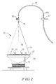
- the continuous dereeling apparatus 10 includes a frame member 20 upon which the wire guide member 18 is slidably mounted and an auxiliary support member 21 (FIG. 2), at substantially the same level or plane as the frame member 20, which stabilizes and provides for the pivotal movement of the wire guide member 18 and associated conduit 40 from one position where the guide member is coaxially aligned with the axis of one spool to a second position where the guide member is coaxially aligned with the axis of another spool when the trailing end of the wire is fully removed from the first reel or spool and the leading end of the wire on the adjacent second reel is then removed through the guide wire member 18.
- FIG. 2 auxiliary support member 21
- the guide member 18 is comprised of an L-shaped bracket member 28 which has an opening 29 therein adapted to receive a bushing member 34 which is comprised of a teflon, other resistance-free material or bearing structure.
- the bushing 34 is sized and adapted to engage the frame member 20 and to permit the guide member 18 to travel back and forth upon the frame member 20 in a substantially resistant-free manner.
- the guide member outlet 18a and guide member coupling or bearing 18b of the upper guide member 18 slidably mounted on frame member 20 is attached to a flexible conduit member 40 which is pivotally anchored to the auxiliary support member 21 (FIG. 2).
- the conduit 40 substantially linear when unconfined, has an inlet end 40a mounted to the guide member outlet 18a and rotatable coupling 18b and an outlet end 40b pivotally anchored to the auxiliary support member 21.
- the conduit 40 has a predetermined arc between the anchored inlet and outlet ends. This predetermined arc of the conduit provides an outward biasing force which positions and maintains the guide member 18 against stop member 17 mounted on frame member 20.
- the stop members 17 facilitate positioning of the guide member 18 during wire removal substantially coaxial with the axis of the coil from which wire is being withdrawn.
- the spring tension range of the predetermined arc of the conduit ranges between a minimum of about 225 g (0.5 lb) to a maximum of about 2.25 kg (5 lb) to maintain the guide member against stop 17.
- the preferred tension is about 680 g (1.5 lb).
- the first convolution of wire is started to be removed from the adjacent second coil and the back tension on the wire engaging the guide member causes the guide member to overcome the spring tension of the conduit and slide along the support frame member 20 until the guide member engages stop 17 and is coaxially aligned with the coil axis of the second wire coil, as shown in FIG. 3.
- the back tension on the wire resulting from the wire engaging the brush filament 27 from the adjacent second wire coil is sufficient to overcome the biasing force provided by the predetermined arc of the conduit on the upper guide member to permit the guide member to be shifted coaxially from the axis of one coil to another.
- the shifting movement of the guide member 18 along the frame member 20 between positions coaxially of the coil axis of the coils is controlled and maintained by the force of the length of the arc of the conduit 40 between the wire guide outlet end 18a and the conduit outlet end 40a which is pivotally mounted to axially support member 21.
- the outlet end of the conduit 40b is pivotally anchored by bracket 43 to the auxiliary support frame 21 at a point substantially intermediate the distance between the coil axis 50 of coils 12 and 14.
- the arc and tension forces on the guide member positions and maintains the guide member against stop 17 coaxially of the coil axis.
- the back tension or drag encountered between the removed wire entering the guide member creates a force on the guide member which is greater that the biasing force imposed on the guide member, causing the guide member 18 to be positioned against stop 17 coaxially above with the new coil axis.
- FIG. 3 the movement of the guide member 18 and conduit 40 between coaxial positions with respect to coil 14 and the adjacent coil 12 is illustrated.
- the conduit attached to guide member 18 moves along frame member 20 to a final position wherein the guide member engages stop 17 and is positioned coaxially of the axis of coil 12.
- the outlet end 40b of the conduit 40 is pivotally mounted to bracket 43 mounted on support member 21, intermediate the axis of coils 12 and 14, as shown in FIGS. 1 and 3.
- FIGS. 5-8 Another embodiment of the present invention is shown in FIGS. 5-8, wherein the guide member 18 is secured to a biasing member 30 which is pivotally anchored by bracket 43 to the auxiliary support member 21.
- the biasing member 30 includes a central shaft 31, a spring member 32 and a tensioning device or stop 33, which permits adjustment of the biasing member 30 to maintain the proper tension on the guide member 18 to maintain the guide member positioned substantially coaxially of the axis of coil reel during the removal of the wire from the particular coil or reel.
- the movement of the guide member 18 and the biasing member 30 during transfer of the wire from the trailing wire end 15a of reel 14 to the leading wire end 15b of reel 12 results in the movement of the biasing member 30 from a fully extended position, wherein the guide member is coaxially located with respect to the coil axis of coil 14, to a position where the guide member 18 is coaxially positioned with respect to the coil axis of reel 12.
- the biasing member 30 maintains the guide member 18 against stop 17 and the spring tension, asserted by the biasing member, is sufficient to maintain the guide member 18 in position coaxially of the coil axis.
- the pulling force of the welding wire through the guide member 18 overcomes the spring tension of the biasing member 30 to permit the guide member to slidably move upon the frame member 20 to a position wherein the guide member 18 is positioned coaxially of reel 12, as shown in FIGS. 5 and 7.
- the guide member 18 cooperates with an upper guide tube or conduit 40 through which the welding wire is pulled and removed, which tube is directed to a robotic welding machine, not shown. It should be noted that the conduit 40b does not need to be attached or located at the pivot area or bracket 43 on auxiliary frame 21.
- the guide member 18 and conduit 40 have a leaf spring member 44 associated therewith which imparts a tension to the guide member to position the member substantially coaxially of the coil axis from which wire is being removed.
- the leaf spring 44 imparts a spring tension of between about 225 g to 2.25 kg (0.5 to 5 lb) on the guide member 18.
- FIG. 11 the movement of the guide member 18 and conduit 40 between coaxial positions with respect to coil 14 and adjacent coil 12 is illustrated.
- the conduit 40 attached to guide member 18 and associated with leaf spring member 44 moves along frame member 20 to a final position wherein the guide member engages stop 17 and is positioned coaxially of the axis of coil 12.
- the outlet end 40 of the conduit is pivotally mounted to bracket 43 mounted on support member 21 intermediate the axis of coils 12 and 14, as shown in FIGS. 9 and 11.
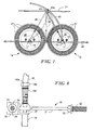
- FIGS. 12 and 13 schematically illustrate a mechanically counter-balanced structure for the sliding movement of the guide member 18 between positions substantially coaxial with respect to the coil axes.
- the guide member 18 is coaxially centred over a coil (not shown), with the wire 15 being directed through the guide member 18.
- the wire 15 may exit the guide member 18 in any direction through a conduit (not shown).
- the guide member 18, as discussed before, is pivotally attached to one end of a lever 45, with the other end of the lever attached to a hanging weight 46.
- the lever includes a channel opening 45a which is pivotally mounted by pin 48 to support frame 21 intermediate the stop members 17.
- the first convolution of wire causes the guide member 18 to move from position A to position B.
- the movement of the guide member 18 is substantially equi-distant between the coils 12 and 14, as shown by position C in FIG. 13, the hanging weight 46 is suspended vertically. Further movement of the guide member 18 and lever 45 overcomes the counter-balance force and moves to position B, as shown in dashed lines. In such a position, the guide member 18 engages stop 17 and is substantially positioned coaxially of coil axis 50 of coil 12.
- the utilization of the mechanical counter-balance structure provides a force on the guide member 18 that is substantially less than spring biased systems. Such a structure would have advantages when fine wires are being removed from the coils.
- the payoff assembly 22 includes a flange portion 24 which is a smooth arcuate shaped structure which permits the wire to be readily pulled over the surface thereof and through to the guide member. Neither the flange portion 24 nor the brush member 25 rotates when they are mounted to the reel flanges 12a and 14a.
- the circular brush member 25 and radially extending tines or brush fingers 27 provide a sufficient back tension to the wire to maintain the wire in a proper location on the coil to prevent entanglements on stopping and starting during withdrawal of the wire from the respective coil or reel.
- the guide member 18 is slidably mounted on frame member 20 by an L-shaped member having a plastic or teflon bearing or bushing structure, any type cross-sectional configuration of the frame member which permits the slidable movement of the guide member back and forth over the coil axis of each of the respective coils is within the scope of the present invention.
- the wire exiting the guide member may be directed in any direction at any location including the pivot location on auxiliary member 21, except for the embodiment utilizing the arc tension of the conduit tube 40.
Landscapes
- Unwinding Of Filamentary Materials (AREA)
- Guides For Winding Or Rewinding, Or Guides For Filamentary Materials (AREA)
- Tyre Moulding (AREA)
Applications Claiming Priority (2)
| Application Number | Priority Date | Filing Date | Title |
|---|---|---|---|
| US34476 | 1998-03-04 | ||
| US09/034,476 US5971308A (en) | 1998-03-04 | 1998-03-04 | Wire transfer assembly |
Publications (2)
| Publication Number | Publication Date |
|---|---|
| EP0940362A2 true EP0940362A2 (fr) | 1999-09-08 |
| EP0940362A3 EP0940362A3 (fr) | 1999-11-17 |
Family
ID=21876668
Family Applications (1)
| Application Number | Title | Priority Date | Filing Date |
|---|---|---|---|
| EP99300735A Withdrawn EP0940362A3 (fr) | 1998-03-04 | 1999-02-01 | Dispositif pour transférer des fils métalliques |
Country Status (4)
| Country | Link |
|---|---|
| US (1) | US5971308A (fr) |
| EP (1) | EP0940362A3 (fr) |
| JP (1) | JPH11263535A (fr) |
| CA (1) | CA2256869A1 (fr) |
Cited By (1)
| Publication number | Priority date | Publication date | Assignee | Title |
|---|---|---|---|---|
| CN102424308A (zh) * | 2011-08-24 | 2012-04-25 | 泰博制钢股份有限公司 | 钢丝放线装置 |
Families Citing this family (35)
| Publication number | Priority date | Publication date | Assignee | Title |
|---|---|---|---|---|
| USRE40351E1 (en) * | 1996-07-24 | 2008-06-03 | Lincoln Global, Inc. | Mechanism for braking the unwinding of a bundle of metallic wire housed in a drum |
| SE0101749L (sv) * | 2001-05-18 | 2002-04-23 | Esab Ab | Anordning vid svetstrådsmatning, trådorienteringslöpare, metod och användning |
| US7615718B2 (en) * | 2003-05-30 | 2009-11-10 | Toyota Moto Engineering & Manufacturing North America, Inc. | Apparatus and method for supplying a continuous source of wire |
| US7041932B2 (en) | 2003-05-30 | 2006-05-09 | Toyota Motor Manufacturing North America, Inc. | Apparatus and method for supplying a continuous source of wire |
| US7100863B2 (en) * | 2003-12-16 | 2006-09-05 | Lincoln Global, Inc. | Floating liner |
| US7191968B2 (en) * | 2004-05-19 | 2007-03-20 | National Standard Company | System for handling welding wire and method of handling welding wire using the system |
| US7220942B2 (en) * | 2004-09-30 | 2007-05-22 | Lincoln Global, Inc. | Feeder for endless welding wire |
| US20060249611A1 (en) * | 2005-05-03 | 2006-11-09 | Lincoln Global, Inc. | Endless wire container and method of using the same |
| US7309038B2 (en) * | 2005-05-27 | 2007-12-18 | Lincoln Global, Inc. | Endless wire container and method of using the same |
| US20070175965A1 (en) * | 2006-02-02 | 2007-08-02 | Lincoln Global, Inc. | System and method of providing endless welding wire |
| US20080156925A1 (en) * | 2007-01-03 | 2008-07-03 | Elco Enterprises, Inc. | Wire Dispensing System |
| EP2288469B1 (fr) | 2008-05-27 | 2013-04-10 | AWDS Technologies SRL | Système de guidage de fil |
| EP2174741B1 (fr) | 2008-10-07 | 2012-06-20 | SIDERGAS SpA | Couvercle pour conteneur de fil-électrode à souder |
| US7938352B2 (en) * | 2009-03-10 | 2011-05-10 | Lincoln Global, Inc. | Wire dispensing apparatus for packaged wire |
| EP2456590B1 (fr) | 2009-07-20 | 2015-09-09 | AWDS Technologies SRL | Gaine de guidage de fil, en particulier une gaine de fil de soudure, comprenant un moyen de sollicitation entre des corps de guidage articulés |
| US8235211B2 (en) * | 2009-08-21 | 2012-08-07 | Sidergas Spa | Retainer for welding wire container, having fingers and half-moon shaped holding tabs |
| US8393467B2 (en) | 2009-08-21 | 2013-03-12 | Sidergas Spa | Retainer for welding wire container, having fingers and half-moon shaped holding tabs |
| SE534408C2 (sv) * | 2009-11-25 | 2011-08-09 | Metso Paper Inc | Anordning och förfarande för avlindning av tråd från en spole |
| US20110215182A1 (en) * | 2010-03-04 | 2011-09-08 | Kiswel, Inc. | Methods and Apparatus for Continuous Winding of Spools and Products Made Therefrom |
| US8389901B1 (en) | 2010-05-27 | 2013-03-05 | Awds Technologies Srl | Welding wire guiding liner |
| US8882018B2 (en) | 2011-12-19 | 2014-11-11 | Sidergas Spa | Retainer for welding wire container and welding wire container with retainer |
| US9421633B2 (en) | 2012-10-09 | 2016-08-23 | Lincoln Global, Inc. | Bulk wire delivery system |
| US10294065B2 (en) | 2013-06-06 | 2019-05-21 | Sidergas Spa | Retainer for a welding wire container and welding wire container |
| US10343231B2 (en) | 2014-05-28 | 2019-07-09 | Awds Technologies Srl | Wire feeding system |
| US10010962B1 (en) | 2014-09-09 | 2018-07-03 | Awds Technologies Srl | Module and system for controlling and recording welding data, and welding wire feeder |
| US10350696B2 (en) | 2015-04-06 | 2019-07-16 | Awds Technologies Srl | Wire feed system and method of controlling feed of welding wire |
| US9975728B2 (en) | 2015-09-10 | 2018-05-22 | Sidergas Spa | Wire container lid, wire container and wire feeding system |
| JP2019529168A (ja) * | 2016-08-31 | 2019-10-17 | バーテル マシーナリー システムズ リミテッド ライアビリティ カンパニー | ビードワイヤー巻き出しシステム |
| US9950857B1 (en) | 2016-10-17 | 2018-04-24 | Sidergas Spa | Welding wire container |
| US11278981B2 (en) | 2020-01-20 | 2022-03-22 | Awds Technologies Srl | Device for imparting a torsional force onto a wire |
| US11174121B2 (en) | 2020-01-20 | 2021-11-16 | Awds Technologies Srl | Device for imparting a torsional force onto a wire |
| CN113942886B (zh) * | 2020-07-16 | 2023-05-02 | Ykk株式会社 | 线状体供给装置 |
| CN111762621A (zh) * | 2020-07-23 | 2020-10-13 | 东莞市精铁机械有限公司 | 一种双臂框式放线架 |
| CN113371547B (zh) * | 2021-07-04 | 2023-06-30 | 孟凡星 | 旋转放线式放线装置及用该装置放线的方法 |
| KR20250029440A (ko) * | 2023-08-23 | 2025-03-05 | 삼성전자주식회사 | 와이어 공급 모듈 및 이를 포함하는 와이어 본딩 장치 |
Family Cites Families (41)
| Publication number | Priority date | Publication date | Assignee | Title |
|---|---|---|---|---|
| US986020A (en) * | 1909-11-01 | 1911-03-07 | Jackson Fence Company | Wire-feeder. |
| US1834159A (en) * | 1928-10-12 | 1931-12-01 | Gerrard Co Inc | Wire holder |
| US1830449A (en) * | 1930-02-03 | 1931-11-03 | George G Swank | Continuous wire supply system |
| US2360741A (en) * | 1941-10-01 | 1944-10-17 | American Steel & Wire Co | Wire distributor for wire-drawing machines |
| US2774548A (en) * | 1953-02-04 | 1956-12-18 | Western Electric Co | Wire payoff apparatus |
| US2842323A (en) * | 1953-09-03 | 1958-07-08 | Western Electric Co | Flyer for supply stands |
| US2784921A (en) * | 1954-04-02 | 1957-03-12 | United States Steel Corp | Pay-off mechanism for dead reels |
| US2942802A (en) * | 1955-08-30 | 1960-06-28 | Western Electric Co | Transfer device for guiding strand as it is continuously unwound from spools |
| US3010674A (en) * | 1955-09-07 | 1961-11-28 | Armco Steel Corp | Wire take-off device |
| FR1146262A (fr) * | 1956-03-24 | 1957-11-08 | Geoffrey-Delore Sa | Dispositif pour dévider en continu du fil à partir de fûts |
| US2880305A (en) * | 1958-04-24 | 1959-03-31 | Union Carbide Corp | Welding wire feed |
| US2929575A (en) * | 1958-06-30 | 1960-03-22 | Coulter & Mckenzie Machine Com | Flyer type wire coiling machine |
| US2944755A (en) * | 1959-01-05 | 1960-07-12 | Western Electric Co | Cut-over mechanism for advancing strands |
| DE1238423B (de) * | 1964-11-09 | 1967-04-13 | Licentia Gmbh | Bremsscheibe fuer Wickelautomaten |
| US3298631A (en) * | 1965-03-25 | 1967-01-17 | Cf & I Steel Corp | Apparatus for paying off wire from reel-less coils |
| US3425647A (en) * | 1966-10-24 | 1969-02-04 | Advanced Wyrepak Co Inc | Wire take-off device |
| US3556370A (en) * | 1968-12-18 | 1971-01-19 | Nat Standard Co | Let-off apparatus |
| US3567152A (en) * | 1969-09-09 | 1971-03-02 | Raymond A Heisler | Unreeling mechanism for wire and tubing |
| US3717315A (en) * | 1970-12-02 | 1973-02-20 | Wyrepak Ind Inc | Take-apart spool for wire and the like |
| GB1447633A (en) * | 1973-03-01 | 1976-08-25 | Bicc Ltd | Winding wire and other flexible material |
| US4017037A (en) * | 1975-03-31 | 1977-04-12 | Kovaleski Joseph J | Tension brush for wire spool |
| US3972489A (en) * | 1975-05-16 | 1976-08-03 | Kovaleski Joseph J | Tension brush with adjustable brake |
| US3998403A (en) * | 1975-10-07 | 1976-12-21 | Kovaleski Joseph J | Supporting fixtures for wire-carrying spools |
| US3997127A (en) * | 1975-10-14 | 1976-12-14 | Kovaleski Joseph J | Wire pay-off cap assembly |
| US4055314A (en) * | 1976-09-17 | 1977-10-25 | Wyrepak Industries, Inc. | Wire pay-off cap assembly for wire spools |
| US4062505A (en) * | 1976-10-01 | 1977-12-13 | Wyrepak Industries | Snap-on, wire pay-off cap assembly |
| US4140289A (en) * | 1977-11-28 | 1979-02-20 | Wyrepak Industries, Inc. | Disposable, wire storage and pay-out spool |
| US4171783A (en) * | 1978-05-12 | 1979-10-23 | Phelps Dodge Industries, Inc. | Filament dereeling apparatus |
| US4269371A (en) * | 1980-02-29 | 1981-05-26 | Wyrepak Industries, Inc. | Composite, heavy-duty spool with plastic end cones |
| US4298174A (en) * | 1980-05-21 | 1981-11-03 | Wyrepak Industries, Inc. | Wire take-off device |
| US4396168A (en) * | 1981-02-24 | 1983-08-02 | Allied Corporation | Multiple package thread transfer alignment guide system |
| US4377264A (en) * | 1981-06-22 | 1983-03-22 | Wyrepak Industries, Inc. | Spool handling device |
| US4441692A (en) * | 1982-04-30 | 1984-04-10 | Wyrepak Industries, Inc. | Rubber-lagged sheave |
| US4482340A (en) * | 1982-09-28 | 1984-11-13 | Wyrepak Industries, Inc. | Low-friction thin-hub plastic multi-part sheave |
| US4508290A (en) * | 1984-02-06 | 1985-04-02 | Wyrepak Industries, Inc. | Cap assembly with friction drag on tension brush |
| US4572458A (en) * | 1984-11-14 | 1986-02-25 | American Barmag Corporation | Compact creel for large diameter yarn supply packages |
| US4768364A (en) * | 1986-11-04 | 1988-09-06 | Wyrepak Industries, Inc. | Continuous coiling machine for rod and strip stock |
| US5040741A (en) * | 1990-05-09 | 1991-08-20 | Brown Maurice H | Method and apparatus for establishing and maintaining a selected tension on uncoiling wire |
| US5007597A (en) * | 1989-01-31 | 1991-04-16 | Jones Johnnie L | Automatic dispenser for elongated flexible coiled elements |
| CA2071419C (fr) * | 1991-06-18 | 1996-03-19 | William Dimmett Cooper | Rondelle retenue pour contenant a bobine de fil a souder |
| DE4121640A1 (de) * | 1991-06-29 | 1993-01-07 | Kabelmetal Electro Gmbh | Vorrichtung zum ueberkopfablauf von langgestrecktem gut |
-
1998
- 1998-03-04 US US09/034,476 patent/US5971308A/en not_active Expired - Fee Related
- 1998-12-22 CA CA002256869A patent/CA2256869A1/fr not_active Abandoned
-
1999
- 1999-02-01 EP EP99300735A patent/EP0940362A3/fr not_active Withdrawn
- 1999-02-03 JP JP11025736A patent/JPH11263535A/ja active Pending
Cited By (1)
| Publication number | Priority date | Publication date | Assignee | Title |
|---|---|---|---|---|
| CN102424308A (zh) * | 2011-08-24 | 2012-04-25 | 泰博制钢股份有限公司 | 钢丝放线装置 |
Also Published As
| Publication number | Publication date |
|---|---|
| CA2256869A1 (fr) | 1999-09-04 |
| US5971308A (en) | 1999-10-26 |
| EP0940362A3 (fr) | 1999-11-17 |
| JPH11263535A (ja) | 1999-09-28 |
Similar Documents
| Publication | Publication Date | Title |
|---|---|---|
| US5971308A (en) | Wire transfer assembly | |
| EP0822916B1 (fr) | Appareil et procede servant au bobinage ininterrompu d'un filament continu sur des devidoirs a longues extremites internes accessibles | |
| JP3902684B2 (ja) | 綾巻きパッケージを巻成する繊維機械の綾巻きパッケージ交換装置 | |
| US4186861A (en) | Wire accumulator tower | |
| US2227442A (en) | Apparatus for coiling helical wire | |
| US3409238A (en) | Continuous yarn windup apparatus | |
| US4923132A (en) | Doffing truck for a yarn false twisting machine | |
| US4895011A (en) | Continuously balanced apparatus for storing and dispensing elongate materials | |
| KR20010031957A (ko) | 자체 보정형 필라멘트 인장력 제어 디바이스 | |
| EP0919505B1 (fr) | Dispostif de bobinage en particulier pour fils textiles | |
| CN219602902U (zh) | 一种改进的防缠绕的收卷装置 | |
| US6000656A (en) | Space saving wire drawing machine with floor mounted wire coil | |
| CN110706866B (zh) | 一种电缆对绞机 | |
| US2809791A (en) | Continuous dead reel let-off with controlled tension | |
| CN213728601U (zh) | 一种伸线机入线引导装置 | |
| US11198954B2 (en) | Yarn twisting machine | |
| US4518126A (en) | Take-up mechanism | |
| CN223117786U (zh) | 一种用于服装加工的线轴挂架 | |
| US4856267A (en) | Method and apparatus for twisting together lengths of filamentary material | |
| CN220392964U (zh) | 一种丝材收放线绕丝机 | |
| CN118371556B (zh) | 一种超细钢丝连续生产线不间断放线自动切换装置 | |
| CN215159797U (zh) | 一种渔网线盘半自动绕线装置 | |
| US2605973A (en) | Direct driven winding machine and bobbin mounting means | |
| US4354642A (en) | Package support apparatus for forming a creeling tail | |
| JPS6320369B2 (fr) |
Legal Events
| Date | Code | Title | Description |
|---|---|---|---|
| PUAI | Public reference made under article 153(3) epc to a published international application that has entered the european phase |
Free format text: ORIGINAL CODE: 0009012 |
|
| AK | Designated contracting states |
Kind code of ref document: A2 Designated state(s): AT BE DE DK ES FR GB IE IT LU NL SE |
|
| AX | Request for extension of the european patent |
Free format text: AL;LT;LV;MK;RO;SI |
|
| PUAL | Search report despatched |
Free format text: ORIGINAL CODE: 0009013 |
|
| AK | Designated contracting states |
Kind code of ref document: A3 Designated state(s): AT BE CH CY DE DK ES FI FR GB GR IE IT LI LU MC NL PT SE |
|
| AX | Request for extension of the european patent |
Free format text: AL;LT;LV;MK;RO;SI |
|
| AKX | Designation fees paid | ||
| REG | Reference to a national code |
Ref country code: DE Ref legal event code: 8566 |
|
| 17P | Request for examination filed |
Effective date: 20000516 |
|
| RBV | Designated contracting states (corrected) |
Designated state(s): AT BE DE DK ES FR GB IE IT LU NL SE |
|
| STAA | Information on the status of an ep patent application or granted ep patent |
Free format text: STATUS: THE APPLICATION HAS BEEN WITHDRAWN |
|
| 18W | Application withdrawn |
Withdrawal date: 20010703 |