EP0940364A2 - Fahrbar Bauaufzug - Google Patents
Fahrbar Bauaufzug Download PDFInfo
- Publication number
- EP0940364A2 EP0940364A2 EP99103344A EP99103344A EP0940364A2 EP 0940364 A2 EP0940364 A2 EP 0940364A2 EP 99103344 A EP99103344 A EP 99103344A EP 99103344 A EP99103344 A EP 99103344A EP 0940364 A2 EP0940364 A2 EP 0940364A2
- Authority
- EP
- European Patent Office
- Prior art keywords
- arm
- chassis
- unit
- drawbar
- tool according
- Prior art date
- Legal status (The legal status is an assumption and is not a legal conclusion. Google has not performed a legal analysis and makes no representation as to the accuracy of the status listed.)
- Granted
Links
Images


Classifications
-
- B—PERFORMING OPERATIONS; TRANSPORTING
- B66—HOISTING; LIFTING; HAULING
- B66B—ELEVATORS; ESCALATORS OR MOVING WALKWAYS
- B66B9/00—Kinds or types of lifts in, or associated with, buildings or other structures
- B66B9/16—Mobile or transportable lifts specially adapted to be shifted from one part of a building or other structure to another part or to another building or structure
Definitions
- a mobile work tool especially one Elevator device of the type mentioned is from DB-A-4 337 586 discloses a chassis, an arm boom with extendable and collapsible Has telescopic rod elements and a pulling device, folded down in the working position of the implement, is sunk or removed.
- the pulling device is on last telescopic rod element of the arm boom arranged, so that the implement in the transport position without Rolling is to be transported. For transportation needs a rope between the chassis and the drawbar be excited.
- the disadvantage is that the inclination of the arm arm to a unfavorable weight distribution leads. This allows the implement at the place of use after detaching from It is difficult to move the towing vehicle.
- Another disadvantage is that the regulations of the technical surveillance association not be met. These rules require that the Transport the pulling device not removable, but firmly must be connected to the telescopic rod element. Furthermore the braking device must not be disconnected. In the drawbar is in the way of the working position, because the extended arm arm leans against the last one Telescopic rod element. Furthermore, the regulations require that the superstructure has a certain length from the drawbar, which is currently eight meters, not exceeded may be. If the implement is on the last telescopic rod element pulled, compliance with this goes Demand at the expense of the length of the arm arm or the Telescopic poles or their number.
- a movable elevator is known from DE-U-1 892 364, which has a telescopic boom that consists of telescopic rod elements that can be pulled apart and pushed together consists.
- An elevator car can be placed on the telescopic boom up and down.
- For transportation is under the mast a single-axle chassis and a towing device at the top of the mast appropriate. So that the towing device in a towing vehicle can be hung or moved, the mast be lifted by hand.
- the buckle is provided only for the unloading work to facilitate and unload a universal sled to move away from the edge of the roof onto the roof surface.
- the advantages achieved with the invention are in particular in the fact that in the transport position the mobile working device consisting of a chassis and one attached to the chassis Trailer coupling unit exists. This will make them extraordinary strict regulations of the technical surveillance association (TÜV) fulfilled.
- the drawbar unit of the trailer coupling unit puts the arm arm in the transport position of the chassis in a defined position. This can be a substantially horizontal position.
- connection unit in addition to the existing wrist connection from the two parts chassis and arm extension creates the movable chassis for the transport position, can be designed to be non-positive and / or positive. she can be carried out in two variants.
- connection is by at least one mechanical Connection realized.
- a connection can be a conventional bolt connection.
- This bolt connection is on the opposite of the wrist joint Positioned at the end of the chassis.
- This form of connection is easy to use and above all from the outside clearly visible from here. This can be used to check whether it was actually realized.
- connection unit is implemented the working hydraulic cylinder that takes the arm arm from the Working position in the transport position and vice versa brings and is supplemented by a check valve.
- This check valve ensures that the amount of hydraulic oil compared to the lifting cylinder constantly stops and thus the captured one End position after actuation of the shut-off valve is retained.
- the working hydraulic cylinder can only be opened after activating the shut-off valve operate in a known manner. This also complies with the strict requirements of the TÜV Fulfills.
- the fixing units and the fixing bolts can be like follows to be arranged.
- Another fixing unit is located in one of the triangle points opposite Tip as a work fixing recess. In the Transport position is the draw bolt in the transport fixing recess arranged. In the working position, he will pulled out and the released drawbar arm with the Draw studs fixed in the working fixing recess.
- the trailer coupling unit can be used with the trailer coupling related overrun brake with a Brake cylinder and the chassis one with one Brake unit of the wheels acting overrun brake cylinder have, the brake cylinder and the overrun brake cylinder through a transmission unit with each other are connected.
- This transmission unit can at least comprise a hydraulic line. This makes it possible the wheels of the chassis, far from the drawbar lying with an immediately and powerfully appealing Actuate hydraulic brake unit. Beyond that the laying of special brake ropes that cover the whole Arm extensions must be avoided. Above all, can such brake cables no longer have a disruptive effect. Avoided the high friction losses of the long brake cables a brake transmission. If they are posted, they do not have to extra special safety and inspection regulations be adhered to, which you should hang up before the start of the Secure transportation.
- the hydraulic line can be routed through the arm arm become. In addition, it can still through the drawbar linkage, protected in the drawbar unit and in the chassis to be ordered.
- the area covered by the panning of the Drawbar linkage opposite the drawbar holding unit in the Working position can be created by special protective measures be bridged.
- the trailer coupling unit can also be a support wheel have that with an adjustment spindle of one Parking position is to be adjusted in a transport position. This will make the special arrangement of the towbar complemented by the comfort of the jockey wheel.
- the jockey wheel holds the arm extension connected to the chassis in the same in essentially horizontal position as when coupled. As a result, the implement can be shifted without weight parked or not moved on site.
- the jockey wheel and / or the wheels on the chassis are equipped. This is a effective and separate braking of the implement to the Provided places that enable it to move unintentionally can.
- the chassis can be a single-axle frame or a tandem-axle frame be trained. Which chassis to use comes depends on the superstructure and its weight. At this It should be mentioned that all means of movement, such as Chains and Like. Equated the term wheel in the sense of the invention are.
- the telescopic rod elements in the arm arm can in the Transport position by deflecting a conveyor cable and / or a basket fixing device be. This makes installing expensive fixing devices not mandatory.
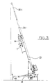
- an elevator device is shown. It has a drawbar unit 1 and a chassis 3, the can be moved by two opposing wheels 7.
- the chassis 3 consists of an arm bracket 33 and a Single-axle chassis 31, which is connected by an arm joint 34 and a bolt connection 41 are connected.
- Fig. 1 shows the bolt connection 41 through which a non-positive connection between the arm boom 33 and the single-axle chassis 31 is manufactured such that the chassis 3 is formed. This job can also be done from a working hydraulic cylinder 42 are taken over by its check valve whose position so determined that it can no longer be moved.
- the wheels 7 are arranged on the single-axle chassis 31, the wheels 7 are arranged.
- the design of the drawbar unit is essential to the invention 1. It consists of a drawbar holding unit 13 which on the Arm bracket 33 is attached. 5 and 6 are as Two rows of screw connections can be seen. It more than two such rows of screws can also be provided become.
- the drawbar holding unit 13 has, as shown in FIG. 5 shows a configuration like that of tail fins for airplanes is known who carry the rudder.
- To the drawbar holding unit 13 is followed by a drawbar linkage 12.
- the drawbar linkage 12, which can be designed as a draw tube can, is on the drawbar holding unit 13 by a drawbar arm 14 held in a clutch swivel 16 held with a safety bolt 24 and in one Transport fixing recess 15 or in a working fixing recess 18 is set.
- the transport fixing recess 15 is in a Triangular tip 17 of the drawbar holding unit 13, as in FIG. 7 shown in detail. It has a pull-out draw bolt 23 on, which is particularly lockable on the opposite side. As can be seen in FIGS. 7 and 8, is located in the drawn position in Fig. 5 the drawbar arm 14 in Inside the side by side, specially tailored Wall profiles of the drawbar holding unit 13, as also FIG. 6 shows. In the working setting recess 18 in the opposite Profile walls of the drawbar holding unit 13 is the pulled out draw bolt 23 inserted.
- the draw bolt 23 can also be used as a safety bolt 24.
- the drawbar linkage 12 consists of an inclined support 26 the beyond the triangle tip 17 through the drawbar holding unit 13 lines in this area continue.
- a drawbar 25 connects to the inclined support 26 which is essentially parallel to the arm arm 33.
- the drawbar 25 is equipped with an overrun brake 39 Hydraulic cylinder 19 and a trailer coupling 22 equipped (see also Fig. 1).
- the Drawbar 25, which is immediately next to the inclined support 26 lies, a support wheel 11 held via an adjusting spindle 22.
- the arm arm 33 has, as shown in FIGS. 1, 2 and 3, telescopic rod elements 35.1, ..., 35.n on, the one another and extendable and out of the arm extension and in this can be inserted. Is on the arm boom 33 a work basket 43.
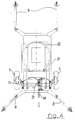
- the single-axle chassis 31 there are 7 front supports in addition to the wheels 8 and rear supports 9 at the opposite ends arranged (see. Fig. 4).
- the supports 8, 9 are in fulcrums adjustable. They have support plates and are in addition to a base, such as a floor, height adjustable.
- the single-axle chassis 31 has it above also a slewing ring 32 with which the arm bracket 33rd can be rotated on the single-axle chassis 31.
- the working hydraulic cylinder 42 the additional with the check valve is equipped, allows the arm extension with the Telescopic rod elements 35.1, ..., 35.n and the work basket 43 from an essentially horizontal transport position in an angled working position.
- the Single-axle chassis 31 also has a Overrun brake cylinder 37, the corresponding brake lines or ropes with a brake unit 71 in the wheels 7 connected is. It is essential that the overrun brake cylinder 37 via a hydraulic line 38 with the brake cylinder 19 the overrun brake 39 is connected. As in particular Fig. 1 shows, the hydraulic line 38 from the overrun brake cylinder 37 by the arm arm 33 of the chassis 3, the Drawbar holding unit 13, drawbar linkage 12, etc. guided. This makes it possible to use the overrun brake cylinder 37 to be installed at any point on the tiller unit 1. In addition to the hydraulic brake device described the single-axle chassis 31 via a chassis handbrake 36, with which the wheels 7 via rope connections in known Way can be braked.
- the trailer coupling 21 of the drawbar unit 1 is on Vehicle hanged. Then the jockey wheel 11 with the adjusting spindle 22 so far up that it is not more touches the ground. With the help of the vehicle Elevator device moved to a site. On site for example from a window of a higher one Floor furniture and the like can be transported.
- the elevator device is reversed with the vehicle the wall in the working position. This approach the elevator device with the help of the vehicle in the working position is only possible because the Traction device arranged at the tip of the arm boom 33 is. Then the jockey wheel 11 is opened with the adjusting spindle the floor and brought it into the position as shown in Fig. 1 is shown. Then the front supports 8 and the rear supports 9 hydraulically or by hand and opposite the floor so that the single-axle chassis 31 effective and above all supported horizontally. Subsequently the aforementioned bolt connection 41 is released or the check valve of the hydraulic cylinder 42 controlled. About that In addition, the tie bolt 23 from the transport fixing recess 15 pulled out.
- the hydraulic cylinder is used 42 the arm arm 33 is brought into its working position, as shown in FIG. 3.
- a swivel hydraulic cylinder 27 that can Drawbar linkage 12 opposite the drawbar holding unit 13 pivoted so far by the released tiller arm be that it puts on the arm boom 33.
- the pivoting can also be done by hand.
- Under mooring is understood here that the drawbar linkage 12 substantially parallel to the arm arm 33 opposite.
- the tiller rotating arm 14 turns around the coupling swivel 16 and swivels into free space, between the profile walls of the tiller unit 13 located.
- the pivoted drawbar linkage 12 with the support wheel in the direction of the arm arm it becomes effective by inserting the Draw bolt 23 set in the work setting recess 18.
- the pull bolt 24 is inserted before the Boom 33 has reached its working position.
- the wheels are in the working position of the elevator device 7 of the single-axle chassis 31 with the help of the chassis handbrake 36 braked.
- the front and rear supports 8, 9 are off the ground solved and the wheels 7 and the support wheel 11 lowered to the ground. Then the front supports, as shown in FIG. 2, folded towards chassis 3 and locked accordingly. Likewise, the rear supports 9 are in the direction of the wheels 7 the single-axle chassis 31 brought up and locked accordingly. The front and rear supports are 8, 9 in Direction of travel.
- the vehicle is driven up to the ready-to-drive elevator device and hooked the trailer hitch 21. After that the support wheel 11 is raised using the adjusting spindle 22, the chassis handbrake 36 released and with the help the drawbar unit 1 the one located on the wheels 7 Chassis 3 removed.
- the overrun brake acts when the elevator device is pulled 39 as if there was a conventional trailer on the towing vehicle. With the help of the brake cylinder 19 is on the hydraulic line every braking command immediately on the overrun brake cylinder transmitted in the single-axle chassis 31.
- the overrun brake cylinder 37 also acts immediately on the brake unit 71 the wheels 7 and ensures the appropriately controlled Braking effect on the wheels 7. This is effective Lurching and breaking out of the chassis 3 when braking avoided.
- the individual telescopic rod elements 35.1, ..., 35.n are transported through their adjustment ropes held. Likewise, the work basket 43 is in the transport position captured.
Landscapes
- Engineering & Computer Science (AREA)
- Structural Engineering (AREA)
- Civil Engineering (AREA)
- Transportation (AREA)
- Automation & Control Theory (AREA)
- Handcart (AREA)
- Jib Cranes (AREA)
- Lift-Guide Devices, And Elevator Ropes And Cables (AREA)
- Types And Forms Of Lifts (AREA)
Abstract
- ein Fahrgestell (31) mit wenigstens einem Rad (7),
- einen Armauslager (33),
der auf dem Fahrgestell (31) höhenverstellbar angeordnet ist,
der mit einer Armgelenkverbindung (34) mit dem Fahrgestell (31) verbunden ist und
der auseinander- und zusammenschiebbare Teleskopstangenelemente (35.1, 35.4) aufweist, - eine Anhängerkupplungseinheit, die an dem Armausleger (33) angeordnet ist, und
- ein Verbindungselement, mit dem in einer Transportstellung das Fahrgestell (31) und der Armausleger (33) verbunden sind.
- einen Armauslager (33),
Description
- ein Fahrgestell mit wenigstens einem Rad,
- einen Armausleger,
der auf dem Fahrgestell höhenverstellbar angeordnet ist, der mit einer Armgelenkverbindung mit dem Fahrgestell verbunden ist und der auseinander- und zusammenschiebbare Teleskopstangenelemente aufweist, - eine Anhängerkupplungseinheit, die an dem Armausleger angeordnet ist, und
- ein Verbindungselement, mit dem in einer Transportstellung das Fahrgestell und der Armausleger verbunden sind
- Fig. 1
- eine Aufzugseinrichtung in einer Transportstellung in einer Seitenansicht,
- Fig. 2
- eine Aufzugseinrichtung gem. Fig. 1 in einer Draufsicht,
- Fig. 3
- eine Aufzugseinrichtung gem. Fig 1 und 2 in einer Arbeitsstellung in einer Seitenansicht,
- Fig. 4
- ein Fahrgestell für eine Aufzugseinrichtung gem. Fig. 1 bis 3 in einer vergrößert dargestellten Draufsicht,
- Fig. 5
- eine Deichseleinheit für eine Aufzugseinrichtung gem. Fig. 1 bis 3 in einer Seitenansicht,
- Fig. 6
- eine Deichseleinheit gem. Fig. 5 in einer Vorderansicht,
- Fig. 7
- einen Schnitt durch eine Deichseleinheit gem. Fig. 5 entlang der Linie VII - VII und
- Fig. 8
- einen Schnitt durch eine Anhängerkupplungseinheit gem. Fig. 5 entlang der Linie VIII - VIII.
- 1
- Deichseleinheit
- 3
- Chassis
- 7
- Rad
- 8
- Vorderstütze
- 9
- Hinterstütze
- 11
- Stützrad
- 12
- Deichselgestänge
- 13
- Deichselhalteeinheit
- 14
- Deichselgelenkarm
- 15
- Transportfestlegeausnehmung
- 16
- Kupplungsdrehgelenk
- 17
- Dreieckspitze
- 18
- Arbeitsfestlegeausnehmung
- 19
- Bremszylinder
- 21
- Anhängerkupplung
- 22
- Verstellungsspindel
- 23
- Zugbolzen
- 24
- Sicherheitsbolzen
- 25
- Deichsel
- 26
- Schrägträger
- 27
- Schwenkhydraulikzylinder
- 31
- Einachsfahrgestellt
- 32
- Drehkranz
- 33
- Armausleger
- 34
- Armgelenkverbindung
- 35.1, ...,35.n
- Teleskopstangenelement
- 36
- Fahrgestell-Handbremse
- 37
- Auflaufbremszylinder
- 38
- Hydraulikleitung
- 39
- Auflaufbremse
- 41
- Bolzenverbindung
- 42
- Arbeits-Hydraulikzylinder mit Sperrventil
- 43
- Arbeitskorb
- 71
- Bremseinheit
Claims (10)
- Fahrbares mobiles Arbeitsgerät, insbesondere Aufzugseinrichtung, das wenigstens aufweist,ein Fahrgestell (31) mit wenigstens einem Rad (7),einen Armausleger (33),
der auf dem Fahrgestell (31) höhenverstellbar angeordnet ist,
der mit einer Armgelenkverbindung (34) mit dem Fahrgestell (31) verbunden ist und
der auseinander- und zusammenschiebbare Teleskopstangenelemente (35.1, ..., 35.n) aufweist,eine Anhängerkupplungseinheit (11, 19, 20, 21, 22, 39), die an dem Armausleger (33) angeordnet ist, undein Verbindungselement (41; 42), mit dem in einer Transportstellung das Fahrgestell (31) und der Armausleger (33) verbunden sind,
dadurch gekennzeichnet,daß am Armausleger (33) eine Deichseleinheit (1) angeordnet ist, die eine Deichselhalteeinheit (13) aufweist, die mit einer Deichselstange (12), die die Anhängerkupplungseinheit (11, 19, 21, 22, 39) hält, durch einen Deichselarm (14) mit wenigstens einer Festlegeeinheit (15, 18) mit einem Festlegebolzen (23) und einem Kupplungsdrehgelenk (16) verbunden ist,daß in einer Arbeitsstellung der Festlegebolzen (23) aus der Festlegeeinheit (15, 18) gezogen ist und der Deichselarm (14) frei in dem Kupplungsdrehgelenk (16) derart bewegbar ist, daß an den aufgerichteten Armausleger (33) die Anhängerkupplungseinheit (11, 19, 21, 22, 39) zu schwenken ist, unddaß in der Transportstellungder Festlegebolzen (23) in der Festlegeeinheit (15, 18) angeordnet und der Deichselarm (14) derart festgelegt ist, daß die Anhängerkupplungseinheit (11, 19, 20, 21, 22, 39) in eine Zugstellung gebracht ist, undder Armausleger (33) auf dem Fahrgestell (31) aufliegt und durch die Armgelenkverbindung (34) und eine weitere Verbindungseinheit (41; 42) als Verbindungselement zu einem auf den Rädern (7) bewegbaren Chassis (3) verbunden ist. - Arbeitsgerät nach Anspruch 1, dadurch gekennzeichnet, daß die Verbindungseinheit, eine mechanische Verbindung (41) ist, die an dem der Armgelenkverbindung (34) gegenüberliegenden Ende des Fahrgestells (31) angeordnet ist.
- Arbeitsgerät nach Anspruch 1, dadurch gekennzeichnet, daß die Verbindungseinheit ein den Armausleger (33) von der Arbeits- in die Transportstellung stellbarer Arbeits-Hydraulikzylinder (42) mit einem Sperrventil ist.
- Arbeitsgerät nach einem der Ansprüche 1 bis 3, dadurch gekennzeichnet, daß in der Deichseleinheit (13) als eine Festlegeeinheit in dessen Dreieckspitze (17) eine Transportfestlegeausnehmung (15) angeordnet ist, mit dem der Deichselarm (14) in der Transportstellung mit einem Zugbolzen (23) als ein Festlegebolzen festzulegen und in der Arbeitsstellung durch dessen Herauslösen freigebbar ist und als eine weitere Festlegeeinheit in dessen der Dreieckspitze (17) gegenüberliegenden Spitze eine Arbeitsfestlegeausnehmung (18) angeordnet ist, mit der Deichselarm (14) in der Arbeitsstellung mit dem Zugbolzen (23) festlegbar ist.
- Arbeitsgerät nach einem der Ansprüche 1 bis 4, dadurch gekennzeichnet, daß die Anhängerkupplungseinheit eine mit einer Anhängerkupplung (21) in Verbindung stehende Auflaufbremse (39) mit einem Bremszylinder (19) und das Fahrgestell (31) einen mit auf eine Bremseinheit (71) der Räder (7) wirkenden Auflaufbremszylinder (37) aufweist und daß der Bremszylinder (19) und der Auflaufbremszylinder (37) durch eine Übertragungseinheit (38) verbunden sind.
- Arbeitsgerät nach einem der Ansprüche 1 bis 5, dadurch gekennzeichnet, daß die Übertragungseinheit eine Hydraulikleitung (38) umfaßt, die wenigstens teilweise im Deichselgestänge (12), in der Deichselhalteeinheit (13), im Armausleger (33) und/oder im Fahrgestell (31) angeordnet ist.
- Arbeitsgerät nach einem der Ansprüche 1 bis 6, dadurch gekennzeichnet, daß die Anhängerkupplungseinheit ein Stützrad (11) aufweist, das mit einer Verstellungsspindel (22) von einer Abstellstellung in die Transportstellung zu verstellen ist.
- Arbeitsgerät nach einem der Ansprüche 1 bis 7, dadurch gekennzeichnet, daß das Stützrad (11) mit einer Stützrad-Handbremse (20) und/oder die Räder (7) am Fahrgestell (31) mit einer Fahrgestell-Handbremse (36) festzubremsen sind.
- Arbeitsgerät nach einem der Ansprüche 1 bis 8, dadurch gekennzeichnet, daß das Fahrgestell als ein Einachsgestell (31) oder ein Tandemachsengestell ausgebildet ist.
- Arbeitsgerät nach einem der Ansprüche 1 bis 9, dadurch gekennzeichnet, daß die Teleskopstangenelemente (35.1, ..., 35.n) im Armausleger (33) in der Transportstellung durch eine Umlenkung eines Förderseils und/oder eine Ar-
Priority Applications (1)
| Application Number | Priority Date | Filing Date | Title |
|---|---|---|---|
| DE29924437U DE29924437U1 (de) | 1998-03-05 | 1999-02-20 | Aufzugseinrichtung |
Applications Claiming Priority (2)
| Application Number | Priority Date | Filing Date | Title |
|---|---|---|---|
| DE19809332A DE19809332C2 (de) | 1998-03-05 | 1998-03-05 | Aufzugseinrichtung |
| DE19809332 | 1998-03-05 |
Publications (3)
| Publication Number | Publication Date |
|---|---|
| EP0940364A2 true EP0940364A2 (de) | 1999-09-08 |
| EP0940364A3 EP0940364A3 (de) | 2001-07-18 |
| EP0940364B1 EP0940364B1 (de) | 2005-01-19 |
Family
ID=7859748
Family Applications (1)
| Application Number | Title | Priority Date | Filing Date |
|---|---|---|---|
| EP99103344A Expired - Lifetime EP0940364B1 (de) | 1998-03-05 | 1999-02-20 | Fahrbar Bauaufzug |
Country Status (2)
| Country | Link |
|---|---|
| EP (1) | EP0940364B1 (de) |
| DE (2) | DE19809332C2 (de) |
Cited By (1)
| Publication number | Priority date | Publication date | Assignee | Title |
|---|---|---|---|---|
| DE10128824C1 (de) * | 2001-06-15 | 2003-01-23 | Boecker Albert Gmbh & Co Kg | Schrägaufzug mit aus mehreren Teleskopschüssen bestehendem Ausleger |
Families Citing this family (2)
| Publication number | Priority date | Publication date | Assignee | Title |
|---|---|---|---|---|
| DE202004008044U1 (de) * | 2004-05-17 | 2005-09-29 | Hermann Paus Maschinenfabrik Gmbh | Fahrbares Arbeitsgerät in Form einer Aufzugsvorrichtung |
| DE102024124238A1 (de) * | 2024-08-23 | 2026-02-26 | Klaas-Alu-Kranbau Gmbh | Hebefahrzeug mit automatisch trenn- und schließbarer Bremsvorrichtung |
Family Cites Families (3)
| Publication number | Priority date | Publication date | Assignee | Title |
|---|---|---|---|---|
| US3178048A (en) * | 1962-03-19 | 1965-04-13 | Howard R Bergman | Portable elevator |
| DE1892364U (de) * | 1962-12-01 | 1964-05-06 | Folke Valdemar | Vorrichtung an einem aufzug. |
| DE4337586C2 (de) * | 1993-11-04 | 1998-12-03 | Alfons Thihatmer | Fahrbares mobiles Arbeitsgerät, insbesondere Aufzugseinrichtung |
-
1998
- 1998-03-05 DE DE19809332A patent/DE19809332C2/de not_active Expired - Fee Related
-
1999
- 1999-02-20 EP EP99103344A patent/EP0940364B1/de not_active Expired - Lifetime
- 1999-02-20 DE DE59911464T patent/DE59911464D1/de not_active Expired - Lifetime
Cited By (1)
| Publication number | Priority date | Publication date | Assignee | Title |
|---|---|---|---|---|
| DE10128824C1 (de) * | 2001-06-15 | 2003-01-23 | Boecker Albert Gmbh & Co Kg | Schrägaufzug mit aus mehreren Teleskopschüssen bestehendem Ausleger |
Also Published As
| Publication number | Publication date |
|---|---|
| EP0940364A3 (de) | 2001-07-18 |
| DE19809332C2 (de) | 2002-01-31 |
| EP0940364B1 (de) | 2005-01-19 |
| DE59911464D1 (de) | 2005-02-24 |
| DE19809332A1 (de) | 1999-09-09 |
Similar Documents
| Publication | Publication Date | Title |
|---|---|---|
| DE4447860C2 (de) | Schleppfahrzeug zum Manövrieren von Flugzeugen | |
| AT523097B1 (de) | Fahrzeugkran mit einem teleskopausleger und fahrzeugkransystem sowie verfahren zur montage einer abspannvorrichtung an den teleskopausleger eines fahrzeugkrans | |
| DE102012110053B4 (de) | Handhabungsvorrichtung zur Handhabung flacher Gegenstände | |
| DE102007039933B4 (de) | Rungenstock | |
| EP0241711B1 (de) | Doppelstöckiger Kraftfahrzeugtransporter | |
| DE3911868C2 (de) | ||
| EP0940364B1 (de) | Fahrbar Bauaufzug | |
| DE2821542A1 (de) | Geraet zum anheben und abtransportieren von kraftfahrzeugen | |
| DE3635328C2 (de) | ||
| EP1483181B1 (de) | Container | |
| DE1941940B2 (de) | Fahrzeug mit Hebevorrichtung für großvolumige Kästen, vorzugsweise aus Beton mit Ausnehmungen im Boden für teleskopisch längenveränderliche Beine der Hebevorrichtung | |
| DE2608523A1 (de) | Mit einem bergungskran ausgeruestetes abschleppfahrzeug in tiefladerbauweise | |
| DE29924437U1 (de) | Aufzugseinrichtung | |
| EP0949184A2 (de) | Transportvorrichtung, insbesondere Ladekran, zum Transport von Grabsteinen, Denkmälern und dgl. | |
| EP0539919B1 (de) | Abstützvorrichtung für Sonderfahrzeuge, insbesondere für fahrbare Betonpumpen | |
| DE19516357A1 (de) | Anordnung bei Ladevorrichtungen für Transportfahrzeuge | |
| DE939672C (de) | Einachs-Abschleppanhaenger fuer Kraftfahrzeuge | |
| DE2733321C2 (de) | Verlastungsgestell für auf- und abrollbare Schnellbaustraßen | |
| DE2927494C2 (de) | Bremswagen für eine Schienenstandbahn | |
| DE29719229U1 (de) | Sattelauflieger mit auskuppelbarem Lademodul | |
| EP4053066A2 (de) | Vorrichtung und verfahren zur montage / demontage eines mobilkranauslegers | |
| DE10024027B4 (de) | Wechselvorrichtung für ein Nutzfahrzeug | |
| DE2848387A1 (de) | Fahrzeug zum transportieren und aufstellen von fertiggaragen | |
| DE102019101505A1 (de) | Mobile Flugzeugtreppe und Verfahren zur motorschonenden Bedienung einer Flugzeugtreppe | |
| DE4337586A1 (de) | Fahrbares mobiles Arbeitsgerät, insbesondere Aufzugseinrichtung |
Legal Events
| Date | Code | Title | Description |
|---|---|---|---|
| PUAI | Public reference made under article 153(3) epc to a published international application that has entered the european phase |
Free format text: ORIGINAL CODE: 0009012 |
|
| AK | Designated contracting states |
Kind code of ref document: A2 Designated state(s): BE DE FR IT NL |
|
| AX | Request for extension of the european patent |
Free format text: AL;LT;LV;MK;RO;SI |
|
| PUAL | Search report despatched |
Free format text: ORIGINAL CODE: 0009013 |
|
| AK | Designated contracting states |
Kind code of ref document: A3 Designated state(s): AT BE CH CY DE DK ES FI FR GB GR IE IT LI LU MC NL PT SE |
|
| AX | Request for extension of the european patent |
Free format text: AL;LT;LV;MK;RO;SI |
|
| 17P | Request for examination filed |
Effective date: 20010903 |
|
| AKX | Designation fees paid |
Free format text: BE DE FR IT NL |
|
| GRAP | Despatch of communication of intention to grant a patent |
Free format text: ORIGINAL CODE: EPIDOSNIGR1 |
|
| GRAS | Grant fee paid |
Free format text: ORIGINAL CODE: EPIDOSNIGR3 |
|
| GRAA | (expected) grant |
Free format text: ORIGINAL CODE: 0009210 |
|
| AK | Designated contracting states |
Kind code of ref document: B1 Designated state(s): BE DE FR IT NL |
|
| REF | Corresponds to: |
Ref document number: 59911464 Country of ref document: DE Date of ref document: 20050224 Kind code of ref document: P |
|
| PLBE | No opposition filed within time limit |
Free format text: ORIGINAL CODE: 0009261 |
|
| STAA | Information on the status of an ep patent application or granted ep patent |
Free format text: STATUS: NO OPPOSITION FILED WITHIN TIME LIMIT |
|
| ET | Fr: translation filed | ||
| 26N | No opposition filed |
Effective date: 20051020 |
|
| REG | Reference to a national code |
Ref country code: FR Ref legal event code: CA |
|
| REG | Reference to a national code |
Ref country code: FR Ref legal event code: TP |
|
| PGFP | Annual fee paid to national office [announced via postgrant information from national office to epo] |
Ref country code: IT Payment date: 20100223 Year of fee payment: 12 Ref country code: FR Payment date: 20100226 Year of fee payment: 12 |
|
| PGFP | Annual fee paid to national office [announced via postgrant information from national office to epo] |
Ref country code: DE Payment date: 20100219 Year of fee payment: 12 |
|
| PGFP | Annual fee paid to national office [announced via postgrant information from national office to epo] |
Ref country code: NL Payment date: 20100215 Year of fee payment: 12 |
|
| PGFP | Annual fee paid to national office [announced via postgrant information from national office to epo] |
Ref country code: BE Payment date: 20100401 Year of fee payment: 12 |
|
| BERE | Be: lapsed |
Owner name: B. *TEUPEN MASCHINENBAUG.- M.B.H. Effective date: 20110228 |
|
| REG | Reference to a national code |
Ref country code: NL Ref legal event code: V1 Effective date: 20110901 |
|
| REG | Reference to a national code |
Ref country code: FR Ref legal event code: ST Effective date: 20111102 |
|
| PG25 | Lapsed in a contracting state [announced via postgrant information from national office to epo] |
Ref country code: BE Free format text: LAPSE BECAUSE OF NON-PAYMENT OF DUE FEES Effective date: 20110228 |
|
| PG25 | Lapsed in a contracting state [announced via postgrant information from national office to epo] |
Ref country code: NL Free format text: LAPSE BECAUSE OF NON-PAYMENT OF DUE FEES Effective date: 20110901 Ref country code: IT Free format text: LAPSE BECAUSE OF NON-PAYMENT OF DUE FEES Effective date: 20110220 |
|
| REG | Reference to a national code |
Ref country code: DE Ref legal event code: R119 Ref document number: 59911464 Country of ref document: DE Effective date: 20110901 |
|
| PG25 | Lapsed in a contracting state [announced via postgrant information from national office to epo] |
Ref country code: FR Free format text: LAPSE BECAUSE OF NON-PAYMENT OF DUE FEES Effective date: 20110228 |
|
| PG25 | Lapsed in a contracting state [announced via postgrant information from national office to epo] |
Ref country code: DE Free format text: LAPSE BECAUSE OF NON-PAYMENT OF DUE FEES Effective date: 20110901 |