EP0940482B1 - Dispositif pour le revêtement sous vide assité par plasma et utilisation - Google Patents
Dispositif pour le revêtement sous vide assité par plasma et utilisation Download PDFInfo
- Publication number
- EP0940482B1 EP0940482B1 EP99104321A EP99104321A EP0940482B1 EP 0940482 B1 EP0940482 B1 EP 0940482B1 EP 99104321 A EP99104321 A EP 99104321A EP 99104321 A EP99104321 A EP 99104321A EP 0940482 B1 EP0940482 B1 EP 0940482B1
- Authority
- EP
- European Patent Office
- Prior art keywords
- vacuum
- evaporator
- vacuum arc
- coating system
- plasma coating
- Prior art date
- Legal status (The legal status is an assumption and is not a legal conclusion. Google has not performed a legal analysis and makes no representation as to the accuracy of the status listed.)
- Expired - Lifetime
Links
- 239000000758 substrate Substances 0.000 claims description 37
- 238000000576 coating method Methods 0.000 claims description 29
- 239000011248 coating agent Substances 0.000 claims description 28
- 239000000463 material Substances 0.000 claims description 17
- RYGMFSIKBFXOCR-UHFFFAOYSA-N Copper Chemical compound [Cu] RYGMFSIKBFXOCR-UHFFFAOYSA-N 0.000 claims description 10
- 239000010949 copper Substances 0.000 claims description 10
- 229910052802 copper Inorganic materials 0.000 claims description 10
- 238000000151 deposition Methods 0.000 claims description 7
- 230000008021 deposition Effects 0.000 claims description 6
- 230000008020 evaporation Effects 0.000 claims description 6
- 238000001704 evaporation Methods 0.000 claims description 6
- XAGFODPZIPBFFR-UHFFFAOYSA-N aluminium Chemical compound [Al] XAGFODPZIPBFFR-UHFFFAOYSA-N 0.000 claims description 4
- 229910052782 aluminium Inorganic materials 0.000 claims description 4
- 238000005260 corrosion Methods 0.000 claims description 4
- 230000007797 corrosion Effects 0.000 claims description 4
- VNNRSPGTAMTISX-UHFFFAOYSA-N chromium nickel Chemical compound [Cr].[Ni] VNNRSPGTAMTISX-UHFFFAOYSA-N 0.000 claims description 3
- 229910052804 chromium Inorganic materials 0.000 claims description 2
- 229910052759 nickel Inorganic materials 0.000 claims description 2
- PXHVJJICTQNCMI-UHFFFAOYSA-N Nickel Chemical compound [Ni] PXHVJJICTQNCMI-UHFFFAOYSA-N 0.000 claims 2
- VYZAMTAEIAYCRO-UHFFFAOYSA-N Chromium Chemical compound [Cr] VYZAMTAEIAYCRO-UHFFFAOYSA-N 0.000 claims 1
- 229910018487 Ni—Cr Inorganic materials 0.000 claims 1
- 239000004411 aluminium Substances 0.000 claims 1
- 239000011651 chromium Substances 0.000 claims 1
- 239000010410 layer Substances 0.000 claims 1
- 230000003287 optical effect Effects 0.000 claims 1
- 238000000034 method Methods 0.000 description 3
- 239000000969 carrier Substances 0.000 description 2
- 229910001120 nichrome Inorganic materials 0.000 description 2
- 238000004544 sputter deposition Methods 0.000 description 2
- 238000002207 thermal evaporation Methods 0.000 description 2
- 238000001771 vacuum deposition Methods 0.000 description 2
- 239000011364 vaporized material Substances 0.000 description 2
- 229910019974 CrSi Inorganic materials 0.000 description 1
- 229910000640 Fe alloy Inorganic materials 0.000 description 1
- 229910007567 Zn-Ni Inorganic materials 0.000 description 1
- 229910007614 Zn—Ni Inorganic materials 0.000 description 1
- 230000009286 beneficial effect Effects 0.000 description 1
- 238000004140 cleaning Methods 0.000 description 1
- 238000011161 development Methods 0.000 description 1
- 230000018109 developmental process Effects 0.000 description 1
- 238000010894 electron beam technology Methods 0.000 description 1
- 230000035515 penetration Effects 0.000 description 1
- 238000005086 pumping Methods 0.000 description 1
- 230000007704 transition Effects 0.000 description 1
- 238000009834 vaporization Methods 0.000 description 1
- 230000008016 vaporization Effects 0.000 description 1
Images

Classifications
-
- H—ELECTRICITY
- H01—ELECTRIC ELEMENTS
- H01J—ELECTRIC DISCHARGE TUBES OR DISCHARGE LAMPS
- H01J37/00—Discharge tubes with provision for introducing objects or material to be exposed to the discharge, e.g. for the purpose of examination or processing thereof
- H01J37/32—Gas-filled discharge tubes
- H01J37/32009—Arrangements for generation of plasma specially adapted for examination or treatment of objects, e.g. plasma sources
- H01J37/32422—Arrangement for selecting ions or species in the plasma
-
- C—CHEMISTRY; METALLURGY
- C23—COATING METALLIC MATERIAL; COATING MATERIAL WITH METALLIC MATERIAL; CHEMICAL SURFACE TREATMENT; DIFFUSION TREATMENT OF METALLIC MATERIAL; COATING BY VACUUM EVAPORATION, BY SPUTTERING, BY ION IMPLANTATION OR BY CHEMICAL VAPOUR DEPOSITION, IN GENERAL; INHIBITING CORROSION OF METALLIC MATERIAL OR INCRUSTATION IN GENERAL
- C23C—COATING METALLIC MATERIAL; COATING MATERIAL WITH METALLIC MATERIAL; SURFACE TREATMENT OF METALLIC MATERIAL BY DIFFUSION INTO THE SURFACE, BY CHEMICAL CONVERSION OR SUBSTITUTION; COATING BY VACUUM EVAPORATION, BY SPUTTERING, BY ION IMPLANTATION OR BY CHEMICAL VAPOUR DEPOSITION, IN GENERAL
- C23C14/00—Coating by vacuum evaporation, by sputtering or by ion implantation of the coating forming material
- C23C14/22—Coating by vacuum evaporation, by sputtering or by ion implantation of the coating forming material characterised by the process of coating
- C23C14/24—Vacuum evaporation
- C23C14/32—Vacuum evaporation by explosion; by evaporation and subsequent ionisation of the vapours, e.g. ion-plating
- C23C14/325—Electric arc evaporation
-
- C—CHEMISTRY; METALLURGY
- C23—COATING METALLIC MATERIAL; COATING MATERIAL WITH METALLIC MATERIAL; CHEMICAL SURFACE TREATMENT; DIFFUSION TREATMENT OF METALLIC MATERIAL; COATING BY VACUUM EVAPORATION, BY SPUTTERING, BY ION IMPLANTATION OR BY CHEMICAL VAPOUR DEPOSITION, IN GENERAL; INHIBITING CORROSION OF METALLIC MATERIAL OR INCRUSTATION IN GENERAL
- C23C—COATING METALLIC MATERIAL; COATING MATERIAL WITH METALLIC MATERIAL; SURFACE TREATMENT OF METALLIC MATERIAL BY DIFFUSION INTO THE SURFACE, BY CHEMICAL CONVERSION OR SUBSTITUTION; COATING BY VACUUM EVAPORATION, BY SPUTTERING, BY ION IMPLANTATION OR BY CHEMICAL VAPOUR DEPOSITION, IN GENERAL
- C23C14/00—Coating by vacuum evaporation, by sputtering or by ion implantation of the coating forming material
- C23C14/22—Coating by vacuum evaporation, by sputtering or by ion implantation of the coating forming material characterised by the process of coating
- C23C14/50—Substrate holders
- C23C14/505—Substrate holders for rotation of the substrates
Definitions
- the invention relates to a vacuum plasma coating system consisting of a horizontal vacuum chamber, a substrate holder arranged therein, by means of the the substrates during the coating by at least one rotate the horizontal axis and at least one vacuum arc evaporator.
- the invention relates to the application of Vacuum plasma coating system according to the invention.
- the substrates are often arranged in substrate carriers, such that individual substrate carriers with the substrates as Planets within a rotating basket on an associated one Carriages are arranged, the rotating basket itself a Performs rotational movement.
- all known coating sources can be used Species are used. In particular, these are essentially the thermal vacuum evaporators, electron beam evaporators, Cathode sputtering devices or Vacuum arc evaporator.
- the practical selection judges the intended use of the system, i.e. then which substrates should be coated and how as well as from an economic point of view. More recently vacuum coating systems are preferred, with which the coating process is carried out with plasma support can.
- the plasma-supported layer deposition has the Advantage that the layers often have better adhesion and have greater density, resulting in advantageous properties leads.
- the coating sources generally become centric within the rotation circle of the substrate carrier in Rotary basket arranged. However, it is also possible to use the coating sources on the periphery of the vacuum chamber to arrange.
- the geometry of the coating sources will basically the geometry of the substrates or the appropriate substrate carrier adapted so that possible a large amount of the vaporized or atomized Material evenly deposited on the substrates becomes.
- the document DD 300 782 A7 describes a coating system with horizontal vacuum chamber, a rotating drum with horizontal axis for bulk goods, two magnetrons with different target equipment within the Rotary circle of the drum and arranged between the magnetrons Panels to separate the coating rooms at Plasma deposition of the CrSi oxide / NiCr layer system
- thermal evaporators or other evaporators When using thermal evaporators or other evaporators with a weld pool from which the coating material is evaporated, they can only be arranged in practice be that the evaporation takes place upwards.
- JP 62-2253762 A gives a simulated deposition different vaporizable materials, where Zn by means of thermal evaporation and Zn-Ni or Zn-Fe alloy can be vaporized by means of an arc.
- the other coating sources such as the cathode sputtering devices or the cathodic vacuum arc evaporator can also be on the side or above the Substrates are arranged.
- the invention has for its object as a device a vacuum plasma coating system of the type mentioned Specify the way in which it is possible to differentiate High deposition rate materials deposit.
- the invention solves the task for the device those mentioned in the characterizing part of claim 1 Characteristics.
- the essence of the invention is that within a horizontal vacuum plasma coating system with at least a vacuum arc evaporator as well at least one thermal evaporator is arranged.
- This parallel arrangement of different evaporators it is advantageously possible from the thermal Evaporator at high rate such materials as Evaporate aluminum or copper.
- materials such materials as Evaporate aluminum or copper.
- All other materials can be beneficial be deposited plasma-supported in an effective manner be evaporated with a vacuum arc evaporator.
- the invention can be used advantageously, for example be when an electrically highly conductive layer, e.g. B. made of aluminum or copper with a corrosion protection layer should be protected. Leave aluminum and copper out of one very well and at high speed evaporate thermal evaporator. Materials for corrosion protection layers such as Ni, Cr or NiCr are in contrast the thermal evaporation very reactive and lead to excessive wear on evaporator coils or such materials are practically not thermally too evaporate. That is why it is advantageous to use these materials to evaporate from a vacuum arc evaporator.
- an electrically highly conductive layer e.g. B. made of aluminum or copper with a corrosion protection layer should be protected. Leave aluminum and copper out of one very well and at high speed evaporate thermal evaporator. Materials for corrosion protection layers such as Ni, Cr or NiCr are in contrast the thermal evaporation very reactive and lead to excessive wear on evaporator coils or such materials are practically not thermally too evaporate. That is why it is advantageous to use these materials to evaporate from a vacuum arc evaporator
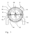
- FIG. 1 shows a section through the front view and Figure 2 shows the side view of Figure 1.
- Figure 1 shows a vacuum chamber 1 with a wall 2 and a pump nozzle 3, through which the vacuum chamber 1 from a Vacuum pumping device can be evacuated.
- the main axis 4 of the vacuum chamber 1 lies in a horizontal Level.
- the substrates 5 to be coated are in one Substrate holder 6, of which several are rotatable in a rotating basket 7 are stored.
- the rotating basket 7 is open stored a mobile carriage-like frame, such that the substrates 5 outside of the vacuum chamber 1 slightly the substrate holders 6 can be held and for Coating coaxial to the main axis 4 in the vacuum chamber 1 can be positioned. Coating turns the rotating basket 7 and the substrates 5 move like a planet around the main axis 4.
- Centric to the rotating basket 7 is in the upper Half of the vacuum chamber 1 an evaporator support 8 and below this an evaporator support 9.
- the evaporator support 8 serves as a support for several thermal Evaporator 10 and is on a front vacuum chamber door 11, which can be seen in Figure 2, supported. A large number of the thermal evaporators 10 are aligned that the vaporized material is on the substrates 5 deposits that are above the thermal Evaporator 10 are located. In this area is the example still a glow electrode 16 arranged.
- the evaporator support 9 serves as a support for several vacuum arc evaporators 12 and is on the other end Vacuum chamber door 13 supported.
- the individual vacuum arc evaporators 12 are in a row arranged parallel to the main axis 4 and the evaporated Material is evaporated downwards.
- the wall 2 of the vacuum chamber 1 are symmetrical two further rows of vacuum arc evaporators 14 arranged, of which the vaporized material is in the central direction is evaporated towards the main axis 4.
- An example of this device according to the invention an electromagnetic shielding layer on the substrates 5 getting produced. They consist of substrates 5 a plastic material.
- the electromagnetic shielding layer should be built up from an approx. 5 ⁇ m thick copper layer with a 150nm thick nickel-chrome layer should be protected against corrosion.
- the vacuum chamber 1 is evacuated and the substrates 5 in one first step in a planetary movement around the Main axis 4 in a glow discharge by means of the glow electrode 16 subjected to cleaning.
- the thermal evaporator 10 connected to voltage and that previously introduced copper evaporated completely.
- the amount of copper is empirically calculated so that the on the 5 deposited layer the desired thickness 2.5 ⁇ m.
- the vacuum arc evaporators 12 and 14 in Started up and with a coordinated schedule the substrates 5 with the copper layer a 150nm thick Nickel-chrome layer deposited.
- the particular advantage of the facility and the process to apply the same is that with very simple Means, without technological interruption and with high deposition rate the relatively thick conductive Layer of copper can be deposited and the thinner nickel-chrome layer with the effective plasma-based Process using the vacuum arc evaporator 12 and 14.
- the invention is of course not based on the described Embodiment limited. So it is without further possible to parallel the two evaporator types operate and deposit mixed layers.
- evaporation could of the copper also take place in a plasma.
Landscapes
- Chemical & Material Sciences (AREA)
- Engineering & Computer Science (AREA)
- Chemical Kinetics & Catalysis (AREA)
- Materials Engineering (AREA)
- Mechanical Engineering (AREA)
- Metallurgy (AREA)
- Organic Chemistry (AREA)
- Physics & Mathematics (AREA)
- Plasma & Fusion (AREA)
- Analytical Chemistry (AREA)
- Physical Vapour Deposition (AREA)
Claims (12)
- Dispositif pour le revêtement sous vide assisté par plasma composé d'une chambre sous vide horizontale (1), d'un support de substrat (6) disposé dans celle-ci à l'aide duquel les substrats (5) sont mis en rotation pendant l'opération de revêtement autour d'au moins un axe horizontal (4), d'au moins un vaporisateur à arc électrique sous vide (12, 14) et d'au moins un vaporisateur thermique (10) disposé à l'intérieur du cercle de rotation des substrats (5).
- Dispositif pour le revêtement sous vide assisté par plasma selon la revendication 1, caractérisé en ce que le vaporisateur à arc électrique sous vide est disposé sous le vaporisateur thermique (10).
- Dispositif pour le revêtement sous vide assisté par plasma selon la revendication 1 ou 2, caractérisé en ce que le vaporisateur à arc électrique sous vide (14) est disposé à l'extérieur du cercle de rotation des substrats dans le sens radial.
- Dispositif pour le revêtement sous vide assisté par plasma selon la revendication 3, caractérisé en ce que le vaporisateur à arc électrique sous vide (14) est intégré dans la paroi (2) de la chambre sous vide (1), de préférence de telle manière que la surface de vaporisation se trouve pour l'essentiel dans le plan de la surface de paroi intérieure de la chambre sous vide (1).
- Dispositif pour le revêtement sous vide assisté par plasma selon la revendication 1 ou 2, caractérisé en ce que le vaporisateur à arc électrique sous vide (12) est disposé à l'intérieur du cercle de rotation des substrats (5).
- Dispositif pour le revêtement sous vide assisté par plasma selon l'une des revendications 1 à 5, caractérisé en ce que la surface de vaporisation du vaporisateur à arc électrique sous vide (12, 14) présente une forme géométrique rectangulaire, ronde ou polygonale.
- Dispositif pour le revêtement sous vide assisté par plasma selon l'une des revendications 1 à 6, caractérisé en ce qu'un obturateur à vapeur est disposé dans l'axe optique entre le vaporisateur thermique (10) et le vaporisateur à arc électrique sous vide (12, 14).
- Dispositif pour le revêtement sous vide assisté par plasma selon l'une des revendications 1 à 6, caractérisé en ce que la chambre sous vide est divisée pour l'essentiel en une moitié supérieure comprenant au moins un vaporisateur thermique (10) et en une moitié inférieure comprenant au moins un vaporisateur à arc électrique sous vide (12, 14) et qu'un obturateur à vapeur à la surface étendue est disposé entre ces espaces.
- Utilisation d'un dispositif pour le revêtement sous vide assisté par plasma selon l'une des revendications 1 à 8 pour déposer plusieurs couches sur le substrat, les matériaux qui peuvent de préférence être vaporisés par voie thermique étant vaporisés à partir du vaporisateur thermique (10) et les matériaux qui ne peuvent pas ou seulement difficilement être vaporisés par voie thermique étant vaporisés par le vaporisateur à arc électrique sous vide (12, 14).
- Utilisation selon la revendication 9, caractérisée en ce que pour déposer une couche de protection électromagnétique sur un substrat, on commence par vaporiser du cuivre ou de l'aluminium à partir du vaporisateur thermique en tant que couche conductrice d'électricité puis à les déposer sur le substrat puis la couche de protection anticorrosion est ensuite réalisée en vaporisant du nickel, du chrome ou du nickel-chrome depuis les vaporisateurs à arc électrique sous vide (12, 14) et en le déposant sur le substrat.
- Utilisation selon la revendication 9 ou 10, caractérisée en ce que différents matériaux sont vaporisés simultanément du vaporisateur thermique et du vaporisateur à arc électrique sous vide (12, 14).
- Utilisation selon la revendication 9 ou 10, caractérisée en ce que pendant la vaporisation à partir du vaporisateur thermique (10), le vaporisateur à arc électrique sous vide (12, 14) est en fonctionnement en vue de générer un plasma à l'intérieur de la chambre sous vide, la déposition du matériau sur les substrats par le vaporisateur à arc électrique sous vide (12, 14) étant empêchée par une réduction de la puissance et/ou un arrangement obturateur.
Applications Claiming Priority (2)
| Application Number | Priority Date | Filing Date | Title |
|---|---|---|---|
| DE19809663 | 1998-03-06 | ||
| DE19809663A DE19809663C1 (de) | 1998-03-06 | 1998-03-06 | Vakuum-Plasma-Beschichtungsanlage und Anwendung derselben |
Publications (3)
| Publication Number | Publication Date |
|---|---|
| EP0940482A2 EP0940482A2 (fr) | 1999-09-08 |
| EP0940482A3 EP0940482A3 (fr) | 2002-01-23 |
| EP0940482B1 true EP0940482B1 (fr) | 2003-05-28 |
Family
ID=7859969
Family Applications (1)
| Application Number | Title | Priority Date | Filing Date |
|---|---|---|---|
| EP99104321A Expired - Lifetime EP0940482B1 (fr) | 1998-03-06 | 1999-03-04 | Dispositif pour le revêtement sous vide assité par plasma et utilisation |
Country Status (2)
| Country | Link |
|---|---|
| EP (1) | EP0940482B1 (fr) |
| DE (2) | DE19809663C1 (fr) |
Families Citing this family (2)
| Publication number | Priority date | Publication date | Assignee | Title |
|---|---|---|---|---|
| DE10142202B8 (de) * | 2001-08-24 | 2008-11-20 | Creavac - Creative Vakuumbeschichtung Gmbh | Hochvakuumbedampfungsanlage |
| AU2003215514A1 (en) * | 2003-02-18 | 2004-09-09 | Creavac-Creative Vakuumbeschichtung Gmbh | High vacuum sputtering installation |
Family Cites Families (2)
| Publication number | Priority date | Publication date | Assignee | Title |
|---|---|---|---|---|
| JPS62253762A (ja) | 1986-04-25 | 1987-11-05 | Mitsubishi Heavy Ind Ltd | Zn合金の蒸着方法 |
| DD300782A7 (de) * | 1988-09-26 | 1992-07-30 | Ardenne Forschungsinst | Einrichtung zum Aufbringen von Schichtsystemen bei statistischer Beschichtung von Schüttgut |
-
1998
- 1998-03-06 DE DE19809663A patent/DE19809663C1/de not_active Expired - Fee Related
-
1999
- 1999-03-04 DE DE59905694T patent/DE59905694D1/de not_active Expired - Lifetime
- 1999-03-04 EP EP99104321A patent/EP0940482B1/fr not_active Expired - Lifetime
Also Published As
| Publication number | Publication date |
|---|---|
| EP0940482A2 (fr) | 1999-09-08 |
| EP0940482A3 (fr) | 2002-01-23 |
| DE19809663C1 (de) | 1999-07-29 |
| DE59905694D1 (de) | 2003-07-03 |
Similar Documents
| Publication | Publication Date | Title |
|---|---|---|
| DE4117518C2 (de) | Vorrichtung zum Sputtern mit bewegtem, insbesondere rotierendem Target | |
| DE3140611C2 (fr) | ||
| DE69226322T2 (de) | Zerstäubungsanlage | |
| EP0632846B1 (fr) | Dispositif a enduire sous vide des produits en vrac | |
| EP0971388A2 (fr) | Dispositif et procédé de dépôt PVD multicouches sur des substrats | |
| DE19860474A1 (de) | Verfahren und Einrichtung zum Beschichten von Substraten mittels bipolarer Puls-Magnetron-Zerstäubung | |
| DE3242854A1 (de) | Verfahren und vorrichtung zur konturierung der dicke von aufgespruehten schichten | |
| DE10100746A1 (de) | Vorrichtung und Verfahren zum Bilden von Filmen | |
| EP0493647A1 (fr) | Cathode de pulvérisation pour dépôt sur un substrat dans un appareil de pulvérisation | |
| DE1914747A1 (de) | Vorrichtung zum mehrseitigen Aufstaeuben | |
| DE60224984T2 (de) | Bogenbeschichtung mit Drehkathoden | |
| EP0940482B1 (fr) | Dispositif pour le revêtement sous vide assité par plasma et utilisation | |
| DE69305725T2 (de) | Magnetron-Zerstäubungsvorrichtung und Dünnfilm-Beschichtungsverfahren | |
| WO2005038077A2 (fr) | Dispositif modulaire pour le revetement de surfaces, notamment pour le revetement modulaire specialise | |
| DE2115590A1 (en) | Cathode sputtering device - has cathode with projecting rim | |
| DE69400404T2 (de) | Beschichtungsvorrichtung zum aufdampfen von metallischem material auf ein substrat | |
| DE3241391A1 (de) | Hochfrequenz-aetztisch mit elektrisch vorgespanntem einfassungteil | |
| DE3612721C2 (fr) | ||
| DE29803948U1 (de) | Vakuum-Plasma-Beschichtungsanlage | |
| DE4025231C2 (de) | Verfahren und Vorrichtung zum reaktiven Beschichten eines Substrats | |
| DE4443740B4 (de) | Vorrichtung zum Beschichten von Substraten | |
| EP4131332A1 (fr) | Cible de pulvérisations multiple | |
| EP1889280A1 (fr) | Pulverisation cathodique magnetron | |
| DE102019132526B4 (de) | Beschichtungsmaschine | |
| DE1690692A1 (de) | Verfahren zum Aufbringen einer Schicht aus anorganischem festem Material auf einer Unterlage durch Kathodenzerstaeubung |
Legal Events
| Date | Code | Title | Description |
|---|---|---|---|
| PUAI | Public reference made under article 153(3) epc to a published international application that has entered the european phase |
Free format text: ORIGINAL CODE: 0009012 |
|
| AK | Designated contracting states |
Kind code of ref document: A2 Designated state(s): AT BE CH CY DE DK ES FI FR GB GR IE IT LI LU MC NL PT SE Kind code of ref document: A2 Designated state(s): CH DE IT LI NL |
|
| AX | Request for extension of the european patent |
Free format text: AL;LT;LV;MK;RO;SI |
|
| RIN1 | Information on inventor provided before grant (corrected) |
Inventor name: WILBERG, RUEDIGER Inventor name: BUECKEN, BERND Inventor name: FALZ, MICHAEL |
|
| PUAL | Search report despatched |
Free format text: ORIGINAL CODE: 0009013 |
|
| AK | Designated contracting states |
Kind code of ref document: A3 Designated state(s): AT BE CH CY DE DK ES FI FR GB GR IE IT LI LU MC NL PT SE |
|
| AX | Request for extension of the european patent |
Free format text: AL;LT;LV;MK;RO;SI |
|
| RIC1 | Information provided on ipc code assigned before grant |
Free format text: 7C 23C 14/50 A, 7H 01J 37/00 B, 7C 23C 14/24 B, 7C 23C 14/32 B |
|
| 17P | Request for examination filed |
Effective date: 20020722 |
|
| AKX | Designation fees paid |
Free format text: CH DE FR GB LI |
|
| GRAH | Despatch of communication of intention to grant a patent |
Free format text: ORIGINAL CODE: EPIDOS IGRA |
|
| RBV | Designated contracting states (corrected) |
Designated state(s): CH DE IT LI NL |
|
| GRAH | Despatch of communication of intention to grant a patent |
Free format text: ORIGINAL CODE: EPIDOS IGRA |
|
| GRAA | (expected) grant |
Free format text: ORIGINAL CODE: 0009210 |
|
| AK | Designated contracting states |
Designated state(s): CH DE IT LI NL |
|
| REG | Reference to a national code |
Ref country code: CH Ref legal event code: EP |
|
| REG | Reference to a national code |
Ref country code: IE Ref legal event code: FG4D Free format text: GERMAN |
|
| REF | Corresponds to: |
Ref document number: 59905694 Country of ref document: DE Date of ref document: 20030703 Kind code of ref document: P |
|
| REG | Reference to a national code |
Ref country code: IE Ref legal event code: FD4D |
|
| PLBE | No opposition filed within time limit |
Free format text: ORIGINAL CODE: 0009261 |
|
| STAA | Information on the status of an ep patent application or granted ep patent |
Free format text: STATUS: NO OPPOSITION FILED WITHIN TIME LIMIT |
|
| 26N | No opposition filed |
Effective date: 20040302 |
|
| PGFP | Annual fee paid to national office [announced via postgrant information from national office to epo] |
Ref country code: CH Payment date: 20050323 Year of fee payment: 7 |
|
| PGFP | Annual fee paid to national office [announced via postgrant information from national office to epo] |
Ref country code: NL Payment date: 20060320 Year of fee payment: 8 |
|
| PG25 | Lapsed in a contracting state [announced via postgrant information from national office to epo] |
Ref country code: LI Free format text: LAPSE BECAUSE OF NON-PAYMENT OF DUE FEES Effective date: 20060331 Ref country code: CH Free format text: LAPSE BECAUSE OF NON-PAYMENT OF DUE FEES Effective date: 20060331 |
|
| REG | Reference to a national code |
Ref country code: CH Ref legal event code: PL |
|
| NLV4 | Nl: lapsed or anulled due to non-payment of the annual fee |
Effective date: 20071001 |
|
| PG25 | Lapsed in a contracting state [announced via postgrant information from national office to epo] |
Ref country code: NL Free format text: LAPSE BECAUSE OF NON-PAYMENT OF DUE FEES Effective date: 20071001 |
|
| PGFP | Annual fee paid to national office [announced via postgrant information from national office to epo] |
Ref country code: IT Payment date: 20110329 Year of fee payment: 13 |
|
| PGFP | Annual fee paid to national office [announced via postgrant information from national office to epo] |
Ref country code: DE Payment date: 20120522 Year of fee payment: 14 |
|
| PG25 | Lapsed in a contracting state [announced via postgrant information from national office to epo] |
Ref country code: IT Free format text: LAPSE BECAUSE OF NON-PAYMENT OF DUE FEES Effective date: 20120304 |
|
| REG | Reference to a national code |
Ref country code: DE Ref legal event code: R119 Ref document number: 59905694 Country of ref document: DE Effective date: 20131001 |
|
| PG25 | Lapsed in a contracting state [announced via postgrant information from national office to epo] |
Ref country code: DE Free format text: LAPSE BECAUSE OF NON-PAYMENT OF DUE FEES Effective date: 20131001 |