EP0940517A1 - Bauelement aus Polycarbonat - Google Patents
Bauelement aus Polycarbonat Download PDFInfo
- Publication number
- EP0940517A1 EP0940517A1 EP99400532A EP99400532A EP0940517A1 EP 0940517 A1 EP0940517 A1 EP 0940517A1 EP 99400532 A EP99400532 A EP 99400532A EP 99400532 A EP99400532 A EP 99400532A EP 0940517 A1 EP0940517 A1 EP 0940517A1
- Authority
- EP
- European Patent Office
- Prior art keywords
- cassette
- plates
- intermediate frame
- plate
- cassettes
- Prior art date
- Legal status (The legal status is an assumption and is not a legal conclusion. Google has not performed a legal analysis and makes no representation as to the accuracy of the status listed.)
- Withdrawn
Links
- 239000004417 polycarbonate Substances 0.000 title claims description 8
- 229920000515 polycarbonate Polymers 0.000 title claims description 8
- 230000004224 protection Effects 0.000 claims abstract description 11
- 239000000853 adhesive Substances 0.000 claims abstract description 6
- 230000001070 adhesive effect Effects 0.000 claims abstract description 6
- 229910052782 aluminium Inorganic materials 0.000 claims abstract description 4
- XAGFODPZIPBFFR-UHFFFAOYSA-N aluminium Chemical compound [Al] XAGFODPZIPBFFR-UHFFFAOYSA-N 0.000 claims abstract description 4
- 239000010959 steel Substances 0.000 claims abstract description 4
- 229910000831 Steel Inorganic materials 0.000 claims abstract description 3
- 238000010276 construction Methods 0.000 claims description 22
- 210000003454 tympanic membrane Anatomy 0.000 claims description 11
- 239000004033 plastic Substances 0.000 claims description 9
- 229920003023 plastic Polymers 0.000 claims description 9
- 239000002390 adhesive tape Substances 0.000 claims description 8
- 210000000959 ear middle Anatomy 0.000 claims description 7
- 238000004519 manufacturing process Methods 0.000 claims description 6
- 230000005855 radiation Effects 0.000 claims description 3
- 238000005304 joining Methods 0.000 claims description 2
- 238000003825 pressing Methods 0.000 claims 3
- 230000000284 resting effect Effects 0.000 claims 3
- 238000005253 cladding Methods 0.000 claims 2
- 239000013013 elastic material Substances 0.000 abstract description 2
- 239000002985 plastic film Substances 0.000 abstract 2
- 239000011248 coating agent Substances 0.000 abstract 1
- 238000000576 coating method Methods 0.000 abstract 1
- 239000000463 material Substances 0.000 description 15
- 229920000297 Rayon Polymers 0.000 description 8
- 239000002964 rayon Substances 0.000 description 8
- 238000007789 sealing Methods 0.000 description 8
- 238000000034 method Methods 0.000 description 5
- 238000005192 partition Methods 0.000 description 5
- 238000009434 installation Methods 0.000 description 4
- 238000009423 ventilation Methods 0.000 description 4
- 230000005494 condensation Effects 0.000 description 3
- 238000009833 condensation Methods 0.000 description 3
- 239000010410 layer Substances 0.000 description 3
- 229910000746 Structural steel Inorganic materials 0.000 description 2
- 229910045601 alloy Inorganic materials 0.000 description 2
- 239000000956 alloy Substances 0.000 description 2
- 238000005452 bending Methods 0.000 description 2
- 230000000694 effects Effects 0.000 description 2
- 239000011521 glass Substances 0.000 description 2
- 239000003292 glue Substances 0.000 description 2
- 239000011229 interlayer Substances 0.000 description 2
- 238000007539 photo-oxidation reaction Methods 0.000 description 2
- XLYOFNOQVPJJNP-UHFFFAOYSA-N water Chemical compound O XLYOFNOQVPJJNP-UHFFFAOYSA-N 0.000 description 2
- 229910000838 Al alloy Inorganic materials 0.000 description 1
- 229910000851 Alloy steel Inorganic materials 0.000 description 1
- RYGMFSIKBFXOCR-UHFFFAOYSA-N Copper Chemical compound [Cu] RYGMFSIKBFXOCR-UHFFFAOYSA-N 0.000 description 1
- 241000238631 Hexapoda Species 0.000 description 1
- 102000000591 Tight Junction Proteins Human genes 0.000 description 1
- 108010002321 Tight Junction Proteins Proteins 0.000 description 1
- 230000006750 UV protection Effects 0.000 description 1
- 238000010521 absorption reaction Methods 0.000 description 1
- 238000004026 adhesive bonding Methods 0.000 description 1
- 239000000470 constituent Substances 0.000 description 1
- 238000004320 controlled atmosphere Methods 0.000 description 1
- 229910052802 copper Inorganic materials 0.000 description 1
- 239000010949 copper Substances 0.000 description 1
- 230000001419 dependent effect Effects 0.000 description 1
- 238000009826 distribution Methods 0.000 description 1
- 239000000428 dust Substances 0.000 description 1
- 238000010410 dusting Methods 0.000 description 1
- 229940082150 encore Drugs 0.000 description 1
- 238000001704 evaporation Methods 0.000 description 1
- 230000008020 evaporation Effects 0.000 description 1
- 230000008595 infiltration Effects 0.000 description 1
- 238000001764 infiltration Methods 0.000 description 1
- 229910052500 inorganic mineral Inorganic materials 0.000 description 1
- 238000009413 insulation Methods 0.000 description 1
- XEEYBQQBJWHFJM-UHFFFAOYSA-N iron Substances [Fe] XEEYBQQBJWHFJM-UHFFFAOYSA-N 0.000 description 1
- 229910052742 iron Inorganic materials 0.000 description 1
- 239000007791 liquid phase Substances 0.000 description 1
- 239000011159 matrix material Substances 0.000 description 1
- 239000011707 mineral Substances 0.000 description 1
- 239000000203 mixture Substances 0.000 description 1
- 230000001681 protective effect Effects 0.000 description 1
- 239000007787 solid Substances 0.000 description 1
- 125000006850 spacer group Chemical group 0.000 description 1
- 239000000126 substance Substances 0.000 description 1
- 230000037072 sun protection Effects 0.000 description 1
- 238000003856 thermoforming Methods 0.000 description 1
- 210000001578 tight junction Anatomy 0.000 description 1
- 238000004078 waterproofing Methods 0.000 description 1
- 230000003313 weakening effect Effects 0.000 description 1
- 229910052725 zinc Inorganic materials 0.000 description 1
Images


Classifications
-
- E—FIXED CONSTRUCTIONS
- E06—DOORS, WINDOWS, SHUTTERS, OR ROLLER BLINDS IN GENERAL; LADDERS
- E06B—FIXED OR MOVABLE CLOSURES FOR OPENINGS IN BUILDINGS, VEHICLES, FENCES OR LIKE ENCLOSURES IN GENERAL, e.g. DOORS, WINDOWS, BLINDS, GATES
- E06B9/00—Screening or protective devices for wall or similar openings, with or without operating or securing mechanisms; Closures of similar construction
- E06B9/24—Screens or other constructions affording protection against light, especially against sunshine; Similar screens for privacy or appearance; Slat blinds
-
- E—FIXED CONSTRUCTIONS
- E04—BUILDING
- E04C—STRUCTURAL ELEMENTS; BUILDING MATERIALS
- E04C2/00—Building elements of relatively thin form for the construction of parts of buildings, e.g. sheet materials, slabs, or panels
- E04C2/54—Slab-like translucent elements
-
- E—FIXED CONSTRUCTIONS
- E04—BUILDING
- E04D—ROOF COVERINGS; SKY-LIGHTS; GUTTERS; ROOF-WORKING TOOLS
- E04D3/00—Roof covering by making use of flat or curved slabs or stiff sheets
- E04D3/02—Roof covering by making use of flat or curved slabs or stiff sheets of plane slabs, slates, or sheets, or in which the cross-section is unimportant
- E04D3/06—Roof covering by making use of flat or curved slabs or stiff sheets of plane slabs, slates, or sheets, or in which the cross-section is unimportant of glass or other translucent material; Fixing means therefor
- E04D3/08—Roof covering by making use of flat or curved slabs or stiff sheets of plane slabs, slates, or sheets, or in which the cross-section is unimportant of glass or other translucent material; Fixing means therefor with metal glazing bars
- E04D2003/0868—Mutual connections and details of glazing bars
- E04D2003/0881—Mutual connections and details of glazing bars on the eaves of the roof
-
- E—FIXED CONSTRUCTIONS
- E04—BUILDING
- E04D—ROOF COVERINGS; SKY-LIGHTS; GUTTERS; ROOF-WORKING TOOLS
- E04D3/00—Roof covering by making use of flat or curved slabs or stiff sheets
- E04D3/02—Roof covering by making use of flat or curved slabs or stiff sheets of plane slabs, slates, or sheets, or in which the cross-section is unimportant
- E04D3/06—Roof covering by making use of flat or curved slabs or stiff sheets of plane slabs, slates, or sheets, or in which the cross-section is unimportant of glass or other translucent material; Fixing means therefor
- E04D3/08—Roof covering by making use of flat or curved slabs or stiff sheets of plane slabs, slates, or sheets, or in which the cross-section is unimportant of glass or other translucent material; Fixing means therefor with metal glazing bars
- E04D2003/0887—Glazing bars for coverings consisting of more than one sheet or glass pane
-
- E—FIXED CONSTRUCTIONS
- E06—DOORS, WINDOWS, SHUTTERS, OR ROLLER BLINDS IN GENERAL; LADDERS
- E06B—FIXED OR MOVABLE CLOSURES FOR OPENINGS IN BUILDINGS, VEHICLES, FENCES OR LIKE ENCLOSURES IN GENERAL, e.g. DOORS, WINDOWS, BLINDS, GATES
- E06B3/00—Window sashes, door leaves, or like elements for closing wall or like openings; Layout of fixed or moving closures, e.g. windows in wall or like openings; Features of rigidly-mounted outer frames relating to the mounting of wing frames
- E06B3/66—Units comprising two or more parallel glass or like panes permanently secured together
- E06B3/67—Units comprising two or more parallel glass or like panes permanently secured together characterised by additional arrangements or devices for heat or sound insulation or for controlled passage of light
- E06B3/6715—Units comprising two or more parallel glass or like panes permanently secured together characterised by additional arrangements or devices for heat or sound insulation or for controlled passage of light specially adapted for increased thermal insulation or for controlled passage of light
Definitions
- the present invention is in the field of materials used in construction of buildings. More specifically it relates to a material of construction for roofing, walls or arches, to a process for producing such a material as well as constructions using such materials.
- plastic materials have coefficients of significant expansion compared to those of materials, for example aluminum, forming the linear elements generally used in the realization of double wall materials. Such a difficulty does not appear with glass because glass, mineral matter, has a coefficient of expansion close to that of linear elements most commonly used. This problem may not be too noticeable when the cassettes are small, or when, due to the conditions for use, for example indoors as in the case of the patent application above, we can be sure that the cassette will not be subject to variations important temperature. If these conditions are met a first solution then consists in choosing the material of the linear element or in treating it so that its coefficient of expansion is as close as possible to that of the plastic used.
- the present invention relates to a double wall material, which is relatively light, impact resistant, easily formable so that curved materials allowing their use for the realization of curved surfaces such only arches.
- the material according to the invention allows spans of dimensions important.
- the material according to the invention facilitates the production of buildings by the fact that it is preferably prepared ready for installation, in the workshop, according to a process which will be described later, thus limiting the intervention time on the building site, the risks of dusting of the internal faces of the walls, and related faults the difficulties in respecting on site the precautions to be taken to achieve a flawless construction ensuring long life for the material.
- the material according to the invention also allows the construction of constructions having a pleasant aesthetic appearance.
- One of the difficulties to solve for the realization of the cassette according to the invention is to ensure mechanical compatibility between the linear element forming the intermediate frame and the plastic plates.
- the solution consists in providing an elastic seal, having a ribbon form, between the plastic material and the intermediate frame.
- the seal serves at the same time fixing between the plastic plate and the linear element.
- It is a ribbon of elastic material impregnated with a glue making it sticky on each side.
- this ribbon has the particularity that the glue with which it is impregnated does not attack plastics. This characteristic is very important to guarantee a good longevity of the cassette and at least the ten-year guarantee.
- the frame is very little apparent by the fact that it is hidden between the two plates gives an aesthetic that can be appreciated by building designers.
- the invention relates to a so-called basic cassette for cover or wall, having the features of claim 1. Advantages are ensured by the characteristics defined in the dependent claims of the claim 1.
- the invention also relates to constructions in which the cassette according to the invention is used. These constructions are defined by the features of the claims.
- the invention also relates to a process for manufacturing the cassette according to the steps defined in a process claim.
- Figure 1 shows a perspective view of a cassette 1 according to preferred the invention. It is essentially composed of an upper plate 2, a lower plate 3, and an intermediate frame 4.
- Plate 2 is shaped rectangular and has two opposite longitudinal edges 5, 6 and two opposite edges transverse 7, 8.
- the plate 3 is rectangular in shape and has two opposite edges longitudinal 9, 10 and two opposite transverse edges 11, 12.
- the shape rectangular plates is chosen because of its ease of realization and use but any other form; for example hexagonal, octagonal or other could suit.
- the intermediate frame 4 is located between the lower 3 and upper plates 2. It consists of linear elements 13, 14, 15, 16.
- the longitudinal linear elements 13, 14 of intermediate frame 4 are parallel to the longitudinal edges 5, 6 9, 10 of the plates 2 and 3 and the transverse linear elements 15, 16 of intermediate frame 4 are parallel to the transverse edges 7, 8, 11, 12 of the plates.
- the longitudinal linear elements 13, 14 and transverse 15, 16 of intermediate frame 4 are in one piece, or optionally connected end to end, but they could, in particular the transverse elements, be constituted by a succession of elements not connected end to end in a contiguous manner.
- These elements have each an upper surface 17, a lower surface 18 and a lateral surface exterior 22.
- the upper 17 and lower 18 surfaces of the linear intermediate frame elements 13, 14, 15 and 16 are flat. These are hollow sections of rectangular section. he it should be noted that the transverse edges 8, 12 of the plates 2, 3 as well as the transverse linear element 16 does not appear in FIG. 1 due to the view in perspective and the fact that the plate 1 is cut in the longitudinal direction.
- the surface lateral lateral 22 of the intermediate frame is flush with the opposite edges longitudinal 5, 6; 9,10, at opposite transverse edges 7, 8; 11.12 plates upper 2 and lower 3, respectively. So these linear elements are at least partially concealed by the means ensuring the sealing between plates adjacent as will be seen later.
- double-sided adhesive tape 19 is provided in order to absorb the differences in expansion between the intermediate frame 4 and the plates 2, 3, as well as a better sealing.
- This ribbon 19 has a face 20 adhering to the intermediate frame and one face 21 adhering to one of the plates 2 or 3.
- This ribbon has the qualities mentioned above. Its absorption possibilities differential expansions are a function of its thickness.
- the thickness must be instantaneous balancing of the internal pressure of the interior volume 24 with the atmospheric pressure, it also allows the evaporation of condensations from vapor forming droplets on the internal faces of the upper plates 2 and lower 3.
- To achieve this ventilation through holes 25 are made in the intermediate frame 4 from the lateral surface 22 of this intermediate frame. These holes are preferably oblong in the longitudinal direction of the tube forming the linear elements of the intermediate frame 4, their sizes and their distribution are such sufficient ventilation, without weakening the frame mechanically interlayer 4. These through holes 25 may not be present when the linear elements do not form a continuous line.
- the openings of frame 4 i.e.
- the spaces between two consecutive linear elements and / or the through holes 25, are plugged at the outer surface 22 of the frame interlayer by a microperforated waterproof tape and single-sided adhesive 26. From even the ends of the tubes are preferably closed by this tape 26.
- the tape 26 known per se allows air and water vapor to pass through but does not pass insects, dust, and water in the liquid phase.
- Dust-cut plates 2 and 3 cut to size and coated with protection on each side, the linear elements cut to dimensions possibly provided with through holes 25, deburred and carefully degreased, the single-sided tape 26, the double-sided tape 19, are available in a dust-free room with controlled atmosphere to have a relative humidity below 45%.
- a lower plate 3 is placed on a frame support not shown and the protection of the upper face is removed.
- a corner of the frame preferably includes a dihedral guide for example a square or more generally forming an angle equal to the angle between two consecutive edges of a plate.
- the double-sided adhesive 19 is then placed on the upper faces 17 and lower 18 of the linear elements 13, 14, 15, 16 intended to form the frame tab 4.
- the adhesive 19 includes protection detachable non-stick on each of its faces 20, 21.
- the linear elements are then placed above the lower plate 3 and kept under pressure for about an hour. We optionally introduce the sun shade 23.
- We large parallel partitions with the external dimensions of a plate, these two large partitions being held together by a large number of small partitions, for example perpendicular to large partitions, all small and large partitions constituting the honeycomb structure.
- Linear elements can be made of aluminum or steel. The maximum dimensions of the cassettes are, for practical reasons of transport and handling conveniences, of the order of 7 meters for the length and 1.5 meters for the width.
- Cassette thicknesses are substantially equal to the sum of the thicknesses of the main constituents, which vary from 3 to 16 mm for plates 2 and 3, and from 15 to 40 mm for linear elements of intermediate frame 4, leading to thicknesses of cassettes variable between around 20 and 70 mm.
- FIG. 2 relates to two optional variants of the invention. These variants are independent of each other.
- FIG. 2 comprises FIGS. 2a, 2b, and 2c.
- FIG. 2a is a perspective view of a cassette according to the invention with a first optional characteristic, according to this characteristic a solar shading 23 is introduced into a free volume 24 of the cassette 1.
- This free volume 24 is the volume which is delimited by the internal faces of the plates 2 and 3 and the surfaces internal side of the intermediate frame 4.
- This sunshade in itself known, is described in patent application FR 2 669 665 A.
- a solar shading 23 can occupy a only part or all of the interior volume 24 of a cassette, depending on the protection requirements requested by the user. In the same construction of cassettes with and without solar shading 23 can be used and distributed so as to obtain in addition to the sun protection effect, an aesthetic effect.
- Figures 2b and 2c are respectively a cross-sectional view of the cassette 1 along lines AA and BB of Figure 2a. They allow you to a second optional feature appears, according to this feature a ventilation of the interior volume 24 of the cassette is provided. This ventilation allows the the greater the greater the difference in expansion to be absorbed.
- greater thicknesses are chosen for lengths of greater bonding and / or for greater thicknesses of plates. So if the upper and lower plates 2 and 3 do not have the same thickness it is the tapes adhering to each of these plates may have thicknesses different.
- the width of the ribbon is equal to or slightly less than the width of the flat surface of the linear element of the intermediate frame 4 on which it adheres.
- the linear elements 13, 14, 15 16 of the frame spacer 4 are made of steel or aluminum alloy conforming to French standard NF A50-411, that is to say having a chemical composition with 0.48 to 053% of Si, 0.18 to 0.21% Fe, 0.04% copper, 0.02 to 0.04% Mg, 0.01% Cr, 0.03% Zn and finally 0.02% of Ti. It may for example be AGS 6060.
- This alloy has a higher coefficient of expansion than other alloys and allows longevity larger with or without the ribbon 19.
- the plates of plastic 2 and 3 are made of polycarbonate and at least the top plate 2 has a outer layer loaded with UV protection products and photo-oxidation. This layer ensures greater longevity to the polycarbonate. The choice of polycarbonate makes it possible to produce transparent cassettes or translucent.
- the cassette 1, called the preferred is constituted by a rectangular intermediate frame 4, having surfaces upper 17, lower 18 plates, and a lateral surface 22.
- Plates polycarbonate upper and lower rectangular 2, 3 having side edges 5, 6, 7, 8 and 9, 10 11, 12 respectively, are fixed on the upper faces 17 and bottom 18 of frame 4 by means of double-sided adhesive tape 19.
- the edges side 5, 6, 7, 8 and 9, 10 11, 12 of the upper and lower plates 2 and 3 are flush with the outer lateral surface 22 of the intermediate frame 4.
- at least the upper plate 2 has an outer layer loaded with protective products against ultraviolet radiation and photo-oxidation.
- the basic or preferred cassette 1 may include variants bearing especially on the shape and nature of the plates, 2, 3, the position, the shape, the nature elements of the intermediate frame 4.
- the plates 2 or 3 can be solid or alveolar.
- An example of a honeycomb plate is composed of two then leave the assembly under pressure for approximately 1 hour.
- Adhesive tapes microperforated 26 are placed so as to block the openings in the surface side 22 of the intermediate frame 4, that is to say the through holes 25 and the possible spaces between linear elements of the intermediate frame 4, and also the ends of the tubes constituting the elements of the intermediate frame 4. They are laid before or after the second plate 2 depending on the accessibility of the elements linear after installation of this plate 2.
- the cassette thus obtained can be used as is, flat or can also be cold bent on site to integrate with vaults if the radius of curvature remains large, for example 12 m for cassettes thinner and 20 m for the thickest cassettes.
- the bending is then obtained directly by fixing the cassette to the supporting structure.
- the sunbreaker consists of two series of intersecting blades, a first series of straight parallel blades 27 and a second series of inclined parallel blades 28.
- the plan of the first blades is perpendicular to the planes of the plates 2, 3.
- the plane of the second blades 28 is inclined for example at 45 ° with respect to the planes of plates 2 and 3.
- the planes of first blades 27 are preferably perpendicular to the planes of the second blades 28.
- At least certain of the blades 27, 28 are pierced with oblong holes 29 whose axis along the large dimension of the hole is preferably perpendicular to the axial direction of the blades.
- Straight blades 27 are equipped with through slots 30, the axial direction of which is made with the axial direction of the straight blades 27 an angle equal to the angle of inclination of the second blades.
- the inclined blades 28 are fitted with through slots 31.
- the inclined blades 28 are introduced into the slots 30 of the straight blades 27, at their own slits 31. In this way, a solar shading whose thickness is equal to the width of the straight slats 27.
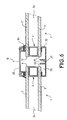
- FIG. 6 This figure represents a sectional view through a plane perpendicular to both the cassettes 1, 1 ', and to a parting line of these two cassettes.
- the two cassettes 1, 1 ' are mounted parallel side by side for example to form part of a blanket.
- the edges for example 6, 10 of the cassette 1 are parallel to the edges 5 ', 9' of the cassette 1 '.
- the ends of the lower faces of each of the cassettes 1, 1 ′ rest on a support profile 32 forming part of the supporting structure or mounted on this supporting structure.
- This profile 32 has a part hollow 73, in the form of a gutter so as to be able to evacuate any infiltration or condensation.
- a cover 35 covers a play space between the parallel edges of the two cassettes 1, 1 '. Sealing is ensured by tightening the cover on the upper surfaces of the cassettes, for example by means of a screw represented by a simple center line 76 coming to be screwed into a thread 33 linked to the bearing profile 32, this tightening puts a seal 34 under pressure.
- FIG. 7 represents an alternative embodiment in which the support 32 is replaced by a support 75, above which is provided a seal 74 comprising a hollow part 73.
- FIG. 8 is a first example of sealed connection of a cassette end.
- it is a connection with a panel tympanum 36, the top of which follows a line of secant slope in the plane of the figure.
- the figure 8 is a cross section of this connection along a plane perpendicular to the line slope of the eardrum 36.
- the top of the eardrum 36 is coated with a profiled eardrum 37 having a part 38 bearing on the support 32, a part 39 coming above the top of the eardrum 36 and housing it, and finally a part 40 descending along the eardrum 36.
- a seal 41 provides sealing between the tympanum profile 37 and the eardrum 36.
- a cover 35 bearing on a seal 34 covers, as in the case of the connection of two cassettes, the junction between the tympanum profile 37 and the cassette 1.
- Figure 9 shows a variant of the connection shown in Figure 8 in which the profile 37 is replaced by a seal 77 covering the eardrum 36 and a at least part of the support 32, and by a height adapter 78.
- the adapter has a surface greater than the height of the top of the upper plate 2.
- the adapter is in the form of a tubular section profile rectangular. One of its faces rests on the gasket 77.
- the upper face located at the same height as the upper face of the cassette 1, receives the cover gasket 34, on which supports the cover 35. The tightening of the cover 35 by means of the nut screws 33, 76 pressurizes the seals 77 and 34.
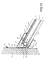
- FIG. 10 is a second example of a tight junction, this time at the point top of a roof joining a wall 42.
- the roof could be that a lean-to against wall 42.
- Figure 8 is a section along a vertical plane parallel to a longitudinal linear element of intermediate frame 4, carried out at the level a cover 35, sealing between two consecutive cassettes, as illustrated Figure 6. The seal is ensured by means of a flap 44, and by various seals as will be shown below.
- a high curb 43 serves as a high support for load-bearing profiles 32.
- the upper curb is elongated in a direction in general horizontal. It has a vertical part 45 fixed to the wall, by means example of screw. To ensure sealing, a seal 47 can be provided between this part. and the wall 42.
- the curb 43 also includes an inclined part 48 connected to the base of the vertical part 45.
- This inclined part 48 serves to support the top of the load-bearing profiles 32.
- the inclined part 48 preferably has the same slope as the profiles 32. These profiles 32 are fixed, for example bolted to this inclined part 48.
- the flap 44 also has a vertical part 46 fixed to the wall 42, and a inclined part 49.
- the inclined part 49 covers the upper part of the end cassette 1 and cover 35.
- seals 50, 51, 34 provide the sealing.
- the seal between the top of the vertical part 46 of the flap and the wall 42 is provided by a seal 50.
- the one between the bottom of the inclined part 49 of the flap 44 and the cover 35 is provided by a seal 51.
- Elastic supports 52, 53 ensure in connection with screws or bolts not shown holding the cassette by pinching 1.
- a first support 53 is pressed between the cassette 1 and the top of the inclined part 48 of the upper curb 43.
- a second support 52 is pressed between the inclined part 49 of the flap 44 and the upper part of the cassette 1.
- the supports 52, 53 are in the form of a strip arranged parallel to the wall 42. These strips are of preferably located to the right of a linear element of the intermediate frame 4 or low distance from it, so as not to deform the plates 2, 3 of the cassettes.
- the various connecting screws were materialized by their only location using centerlines 54-58
- Figure 11 shows the junction of the low point of a roof made with cassettes according to the invention and a wall 59. It is a section along a vertical plane parallel to a longitudinal linear element of intermediate frame 4, made at level of a cover 35, sealing between two consecutive cassettes, such as illustrated in figure 6.
- the wall 59 carries a low curb 60 which is in the form of a streamlined.
- a first part 61 of this profile is used to fix the curb 60 to the wall 59.
- part 61 is applied to the surface top of the wall.
- a second part 62 is parallel to the plates 2, 3 and applied in support of the lower plate 3.
- An intermediate part 63 provides the connection between the first two parts 61, 62.
- this part intermediate 63 has a portion 64 parallel to the slope of the roof. This part receives the lower end 65 of the bearing profile 32 or alternatively, that of the threaded joint 74.
Landscapes
- Engineering & Computer Science (AREA)
- Architecture (AREA)
- Structural Engineering (AREA)
- Civil Engineering (AREA)
- Building Environments (AREA)
Applications Claiming Priority (2)
| Application Number | Priority Date | Filing Date | Title |
|---|---|---|---|
| FR9802872 | 1998-03-05 | ||
| FR9802872A FR2775710A1 (fr) | 1998-03-05 | 1998-03-05 | Cassette polycarbonate pour couverture ou paroi |
Publications (1)
| Publication Number | Publication Date |
|---|---|
| EP0940517A1 true EP0940517A1 (de) | 1999-09-08 |
Family
ID=9523837
Family Applications (1)
| Application Number | Title | Priority Date | Filing Date |
|---|---|---|---|
| EP99400532A Withdrawn EP0940517A1 (de) | 1998-03-05 | 1999-03-03 | Bauelement aus Polycarbonat |
Country Status (2)
| Country | Link |
|---|---|
| EP (1) | EP0940517A1 (de) |
| FR (1) | FR2775710A1 (de) |
Cited By (7)
| Publication number | Priority date | Publication date | Assignee | Title |
|---|---|---|---|---|
| GB2388865A (en) * | 2002-05-20 | 2003-11-26 | Nigel John Sunter | Egg-crate sun-screen louvres |
| WO2009095031A1 (de) * | 2008-01-29 | 2009-08-06 | G.Tröster E. K. | Fertigbauelement |
| WO2009122269A1 (pt) * | 2008-04-03 | 2009-10-08 | Universidade Do Minho | Painel estrutural misto madeira-vidro e seu processo de produção |
| JP2014000226A (ja) * | 2012-06-18 | 2014-01-09 | Krm Corp | 格子状シート材、格子状シート材を用いたブラインド、格子状シート材を用いたバッグ |
| RU2514067C2 (ru) * | 2009-05-22 | 2014-04-27 | Стефен Джон ТРАУЭР | Строительная панель |
| US8889248B2 (en) | 2008-10-31 | 2014-11-18 | Sabic Global Technologies B.V. | Multiwall sheet, an article, a method of making a multiwall sheet |
| FR3148246A1 (fr) | 2023-04-25 | 2024-11-01 | Poly-Pac | Cassette de bardage, et assemblage comprenant de telles cassettes de bardage. |
Citations (9)
| Publication number | Priority date | Publication date | Assignee | Title |
|---|---|---|---|---|
| EP0169509A2 (de) * | 1984-07-23 | 1986-01-29 | Renate Hettling-Denker | Platten- oder quaderförmiges lichtdurchlässiges Bauelement |
| US4621472A (en) * | 1982-09-30 | 1986-11-11 | H. H. Robertson Company | Glazed structural system and components therefor |
| GB2218436A (en) * | 1988-05-13 | 1989-11-15 | Peter Eric Fisher | Heat insulating spaced translucent ceiling panels |
| US4884376A (en) * | 1987-10-13 | 1989-12-05 | Odl, Incorporated | Sun porch |
| EP0376386A1 (de) * | 1988-12-29 | 1990-07-04 | Multifoil B.V. | Verfahren zum Verschliessen der Öffnungen in der Aussenfläche eines flachen mehrschichtigen Kunststoffmaterials und Folie zu diesem Zwecke |
| FR2669665A1 (fr) * | 1990-11-23 | 1992-05-29 | Paralum | Panneau de mur-rideau a grille metallique. |
| DE4217167A1 (de) * | 1992-05-23 | 1993-11-25 | Mertens & Co Glasdachbau Gmbh | Dachverglasung |
| DE4437312A1 (de) * | 1994-10-19 | 1996-05-09 | Roehm Gmbh | Verwendung von Polycarbonatplatten als Material für transparente oder transluzente harte Bedachungen |
| US5568707A (en) * | 1995-01-23 | 1996-10-29 | Ykk Corporation Of America | Solarium structure |
Family Cites Families (1)
| Publication number | Priority date | Publication date | Assignee | Title |
|---|---|---|---|---|
| SE449386B (sv) | 1984-02-10 | 1987-04-27 | Per Froiseth | Takelement |
-
1998
- 1998-03-05 FR FR9802872A patent/FR2775710A1/fr not_active Withdrawn
-
1999
- 1999-03-03 EP EP99400532A patent/EP0940517A1/de not_active Withdrawn
Patent Citations (9)
| Publication number | Priority date | Publication date | Assignee | Title |
|---|---|---|---|---|
| US4621472A (en) * | 1982-09-30 | 1986-11-11 | H. H. Robertson Company | Glazed structural system and components therefor |
| EP0169509A2 (de) * | 1984-07-23 | 1986-01-29 | Renate Hettling-Denker | Platten- oder quaderförmiges lichtdurchlässiges Bauelement |
| US4884376A (en) * | 1987-10-13 | 1989-12-05 | Odl, Incorporated | Sun porch |
| GB2218436A (en) * | 1988-05-13 | 1989-11-15 | Peter Eric Fisher | Heat insulating spaced translucent ceiling panels |
| EP0376386A1 (de) * | 1988-12-29 | 1990-07-04 | Multifoil B.V. | Verfahren zum Verschliessen der Öffnungen in der Aussenfläche eines flachen mehrschichtigen Kunststoffmaterials und Folie zu diesem Zwecke |
| FR2669665A1 (fr) * | 1990-11-23 | 1992-05-29 | Paralum | Panneau de mur-rideau a grille metallique. |
| DE4217167A1 (de) * | 1992-05-23 | 1993-11-25 | Mertens & Co Glasdachbau Gmbh | Dachverglasung |
| DE4437312A1 (de) * | 1994-10-19 | 1996-05-09 | Roehm Gmbh | Verwendung von Polycarbonatplatten als Material für transparente oder transluzente harte Bedachungen |
| US5568707A (en) * | 1995-01-23 | 1996-10-29 | Ykk Corporation Of America | Solarium structure |
Cited By (7)
| Publication number | Priority date | Publication date | Assignee | Title |
|---|---|---|---|---|
| GB2388865A (en) * | 2002-05-20 | 2003-11-26 | Nigel John Sunter | Egg-crate sun-screen louvres |
| WO2009095031A1 (de) * | 2008-01-29 | 2009-08-06 | G.Tröster E. K. | Fertigbauelement |
| WO2009122269A1 (pt) * | 2008-04-03 | 2009-10-08 | Universidade Do Minho | Painel estrutural misto madeira-vidro e seu processo de produção |
| US8889248B2 (en) | 2008-10-31 | 2014-11-18 | Sabic Global Technologies B.V. | Multiwall sheet, an article, a method of making a multiwall sheet |
| RU2514067C2 (ru) * | 2009-05-22 | 2014-04-27 | Стефен Джон ТРАУЭР | Строительная панель |
| JP2014000226A (ja) * | 2012-06-18 | 2014-01-09 | Krm Corp | 格子状シート材、格子状シート材を用いたブラインド、格子状シート材を用いたバッグ |
| FR3148246A1 (fr) | 2023-04-25 | 2024-11-01 | Poly-Pac | Cassette de bardage, et assemblage comprenant de telles cassettes de bardage. |
Also Published As
| Publication number | Publication date |
|---|---|
| FR2775710A1 (fr) | 1999-09-10 |
Similar Documents
| Publication | Publication Date | Title |
|---|---|---|
| EP3230547B1 (de) | Isolierglas-panoramafenster | |
| CA2234297C (fr) | Element vitre a haut pouvoir isolant muni de profile en matiere plastique | |
| WO2017157634A1 (fr) | Vitrage isolant notamment pour enceinte climatique | |
| WO2016131781A1 (fr) | Panneau pour conduits externes de climatisation et produits similaires | |
| CA2997202A1 (fr) | Baie vitree super isolante | |
| WO2017157637A1 (fr) | Vitrage isolant notamment pour enceinte climatique | |
| EP0940517A1 (de) | Bauelement aus Polycarbonat | |
| FR2619587A1 (fr) | Panneau de revetement ou de fenetre pour la surface exterieure d'une facade, et facade equipee d'un tel panneau | |
| WO1998004791A1 (fr) | Dalle de paroi a toile tendue | |
| EP1052362A2 (de) | Doppelverglasung | |
| FR2624161A1 (fr) | Dispositifs d'eclairage et/ou d'aeration ou ventilation destines a etre places en paroi des batiments | |
| EP0320406A1 (de) | Lüftungs- oder Beleuchtungsvorrichtung zur Installation an einer Gebäudewand | |
| FR2690474A1 (fr) | Revêtement isolant, notamment pour toiture de véranda. | |
| FR2627972A1 (fr) | Procede de fabrication de medaillons photographiques et medaillons obtenus selon ce procede | |
| FR2861410A1 (fr) | Perfectionnement aux toitures de verandas ou de verrieres | |
| FR2539443A1 (fr) | Ensemble de revetement a panneaux | |
| FR2481341A1 (fr) | Couverture pour des constructions diverses | |
| FR2509361A1 (fr) | Cadre d'adaptation realise en profiles, pour vitrage | |
| FR2718174A1 (fr) | Profilé porteur à haute résistance thermique et agencement par exemple verrière comportant un tel profilé. | |
| EP3430224A1 (de) | Isolierglaseinheit, insbesondere für ein temperaturgeregeltes möbelstück | |
| FR2531193A1 (fr) | Absorbeur de radiations solaires | |
| EP0675243B1 (de) | Feuerfestes Tragprofil, z.B. für Glaswand und Anordnung umfassend derselben | |
| EP0494029B1 (de) | Metall-Paneel zur Verkleidung oder Ausfüllung von tragenden Strukturen wie Fassaden oder Dächern | |
| FR2589504A1 (fr) | Element de parement utilisable pour constituer une peau d'etancheite pour supports du type facades ou pignons d'immeuble et peau d'etancheite constituee de tels elements montes sur le support par l'intermediaire d'un rail | |
| EP1496320A1 (de) | Sonnenflachkollektor mit geringer Dicke |
Legal Events
| Date | Code | Title | Description |
|---|---|---|---|
| PUAI | Public reference made under article 153(3) epc to a published international application that has entered the european phase |
Free format text: ORIGINAL CODE: 0009012 |
|
| AK | Designated contracting states |
Kind code of ref document: A1 Designated state(s): AT BE CH CY DE DK ES FI FR GB GR IE IT LI LU MC NL PT SE |
|
| AX | Request for extension of the european patent |
Free format text: AL;LT;LV;MK;RO;SI |
|
| AKX | Designation fees paid | ||
| REG | Reference to a national code |
Ref country code: DE Ref legal event code: 8566 |
|
| STAA | Information on the status of an ep patent application or granted ep patent |
Free format text: STATUS: THE APPLICATION IS DEEMED TO BE WITHDRAWN |
|
| 18D | Application deemed to be withdrawn |
Effective date: 20000309 |