EP0940533A1 - Serrure de coffre-fort à commande électrique - Google Patents
Serrure de coffre-fort à commande électrique Download PDFInfo
- Publication number
- EP0940533A1 EP0940533A1 EP99103460A EP99103460A EP0940533A1 EP 0940533 A1 EP0940533 A1 EP 0940533A1 EP 99103460 A EP99103460 A EP 99103460A EP 99103460 A EP99103460 A EP 99103460A EP 0940533 A1 EP0940533 A1 EP 0940533A1
- Authority
- EP
- European Patent Office
- Prior art keywords
- bolt
- control
- lock
- lock according
- housing
- Prior art date
- Legal status (The legal status is an assumption and is not a legal conclusion. Google has not performed a legal analysis and makes no representation as to the accuracy of the status listed.)
- Granted
Links
- 238000002347 injection Methods 0.000 claims description 3
- 239000007924 injection Substances 0.000 claims description 3
- 230000000903 blocking effect Effects 0.000 abstract description 5
- 238000004519 manufacturing process Methods 0.000 description 4
- 239000010902 straw Substances 0.000 description 2
- 238000013475 authorization Methods 0.000 description 1
- 238000005266 casting Methods 0.000 description 1
- 239000007795 chemical reaction product Substances 0.000 description 1
- 239000002184 metal Substances 0.000 description 1
- 238000003860 storage Methods 0.000 description 1
- 229920001169 thermoplastic Polymers 0.000 description 1
- 239000004416 thermosoftening plastic Substances 0.000 description 1
- 230000001960 triggered effect Effects 0.000 description 1
Images



Classifications
-
- E—FIXED CONSTRUCTIONS
- E05—LOCKS; KEYS; WINDOW OR DOOR FITTINGS; SAFES
- E05B—LOCKS; ACCESSORIES THEREFOR; HANDCUFFS
- E05B47/00—Operating or controlling locks or other fastening devices by electric or magnetic means
- E05B47/0001—Operating or controlling locks or other fastening devices by electric or magnetic means with electric actuators; Constructional features thereof
- E05B47/0002—Operating or controlling locks or other fastening devices by electric or magnetic means with electric actuators; Constructional features thereof with electromagnets
-
- E—FIXED CONSTRUCTIONS
- E05—LOCKS; KEYS; WINDOW OR DOOR FITTINGS; SAFES
- E05B—LOCKS; ACCESSORIES THEREFOR; HANDCUFFS
- E05B47/00—Operating or controlling locks or other fastening devices by electric or magnetic means
- E05B47/06—Controlling mechanically-operated bolts by electro-magnetically-operated detents
- E05B47/0607—Controlling mechanically-operated bolts by electro-magnetically-operated detents the detent moving pivotally or rotatively
-
- E—FIXED CONSTRUCTIONS
- E05—LOCKS; KEYS; WINDOW OR DOOR FITTINGS; SAFES
- E05B—LOCKS; ACCESSORIES THEREFOR; HANDCUFFS
- E05B47/00—Operating or controlling locks or other fastening devices by electric or magnetic means
- E05B47/0001—Operating or controlling locks or other fastening devices by electric or magnetic means with electric actuators; Constructional features thereof
- E05B47/0002—Operating or controlling locks or other fastening devices by electric or magnetic means with electric actuators; Constructional features thereof with electromagnets
- E05B47/0006—Operating or controlling locks or other fastening devices by electric or magnetic means with electric actuators; Constructional features thereof with electromagnets having a non-movable core; with permanent magnet
Definitions
- the invention relates to an electrically controllable locker with a housing, a bolt mounted in this housing, a stationary electromagnet and one, with a magnetic armature provided control lever through a dome of the bolt is noted and which affects a locking device.
- Such a lock has become known from EP 0228027.
- Two relatively complicated control and locking levers are pivotally mounted on a common pin and coupled by a tension spring.
- the control lever has a tour pin channel, the locking lever has a magnetic armature.
- Control and locking levers are located in the lock housing under the main latch, while the electromagnet assigned to the armature is accommodated in a rear recess in the lock housing.
- This design not only requires expensive casting tools for the housing provided with front and rear recesses, but also tight tolerances for the manufacture and adjustment of the lever mechanism mentioned.
- the object of the invention is to simplify the manufacture of locks controlled by holding magnet technology and at the same time to increase their reliability. It is also an object of the invention to design the housing, bolt and magnetic mechanism so that, depending on the task, a tumbler lock or a lock cylinder can be inserted into the housing as a second lock.
- a cross slide serves as a locking device, which is deflected against the force of a spring, one end of the control lever being mounted on the cross slide and a control pin of the bolt engaging a control slope of the control lever.
- the cross slide, the control lever and the electromagnet are mounted on the bottom of the box-shaped housing.
- the bolt on which either a tumbler package or a locking cylinder is placed.
- the handle which is only electrically controlled, uses a handle with a straw and double-bit. For these three embodiments, only two different lock ceilings are required, namely one with a double-bit keyhole and one with a pre-shaped recess for the lock cylinder.
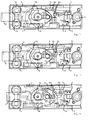
- Fig. 1 designates the box-shaped housing from which the latch 2 protrudes.
- an electromagnet 3 is fastened, against which an armature 4 designed as a triangle bears.
- This anchor is mounted on a control lever 5.
- This lever rests with its left end on a cross slide 6, the blocking block 6a blocks or releases the bolt 2.
- a swivel 7 which can be pivoted about a mandrel 8 fixed to the housing.
- a nose 7a of the vertebra 7 takes the bolt 2 with it.
- the vortex 7 has the task of translating the movement of the key bit or the locking cylinder cam into a larger path.
- the lock housing 1 has three integrally formed hollow columns 1a, 1b, 1c, which are used to fasten the lock.
- a circuit board 9 is held, which carries a microswitch 10 in addition to electronic components. Its function will be explained later.
- a second microswitch is mounted on the circuit board 9, the Touch lever rests on the door surface through a hole in the lock ceiling. If one Burglars attempt to force the lock away by this Microswitch alarm triggered.
- Fig. 2 shows an opening attempt without energization. If the bar 2 is moved to the right by a few millimeters, its control pin 2a pushes the right end of the control lever 5 upwards. The armature 4 lifts off the yoke of the electromagnet 3. The interrogation movement of the bolt 2 is limited in that a locking edge on its underside abuts the locking block 6a of the cross slide 6.
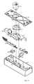
- the quite deep housing 1 is shown three-dimensionally.
- the locking head which emerges from the rectangular opening 1d, is guided between the hollow columns 1a and 1b.
- the main bearing pin 11 guides the tumbler package 12 and other parts.
- Two webs 1e, 1f are formed on the bottom of the housing and guide the cross slide 6.
- Its locking block 6a is normally under the bolt 2.
- a mandrel 6b protrudes into an opening 5a of the control lever 5.
- the control mandrel 2a of the bolt 2 moves the control lever 5 via a control slope 5b.
- the vortex 7, a special tumbler 13 and the tumbler package 12 is shown.
- a lock cover 14 has a double-bit keyhole 14a in addition to the fastening holes.
- a latch 15 is mounted in addition to the bolt 2, which prevents in a known manner that the bolt 2 can be extended and the key removed when the door is not in the frame.
- the latch 15 deviates to the right and displaces a locking block 16 mounted on the housing base, which releases the bolt 2 via a control edge 16a.
- Fig. 4 shows the lock variant in the most common form. The customer or tenant opens the compartment with his double-bit key after a supervisor has checked the access authorization and released the lock with an opening impulse.
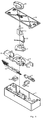
- Fig. 5 shows another design, in which the parts 1, 2, 5, 6, 7, 15, 16 and 17 correspond completely to Fig. 4 .
- a blanket 18 is placed, which carries a locking cylinder 19.
- This lock cylinder rests in a cast-on cylindrical bearing flange 18a of the ceiling.
- the closing cam of the cylinder 19 is designated 19a.
- Fig. 6 shows a variant with only one locking system.
- mechanical closures are dispensed with for cost reasons and the opening is controlled via an input keyboard or a code card.
- the cover 14 corresponds to that of FIG. 4.
- a handle 20 with a straw 21 and double-bit 21a is used.
- a leg spring 22 stabilizes the position of the parts. All other components can be stored pre-assembled so that you can complete any number of the desired lock version in the shortest possible time.
- Fig. 7 shows a design in which the release current is supplied via the head 2b of the bolt 2.
- a contact pin is installed in the locking head 2b, which is connected to the printed circuit board 9 ( FIG. 1 ) via a line 23.
- a second connection is to the mass of the latch or metal housing. The power is then supplied via contact springs in the frame of the cabinet. This has the advantage that no release cable susceptible to faults has to be led from the door to the frame.
- FIG. 8 the current is supplied in the same way as in FIG. 7. In all other details, the structure corresponds to FIG. 5.
- the control lever 5 is shown from the side and from above.
- a mandrel 5c can be seen which receives the armature 4.
- a resilient hook 5d Behind the mandrel 5c is a resilient hook 5d, which yields when the anchor 4 is inserted and prevents this anchor from falling out.
- 10c shows the control lever in perspective from above, FIG. 10d from below. It can be seen that a slot 5e is provided under the hook 5d, which ensures the elastic deformability of the hook 5d.
- the part 5 is injection molded from an impact-resistant thermoplastic, so that it is very accurate and inexpensive to manufacture. Without the use of a spring washer or the like, the anchor 4 is easily installed and held securely.
- the locker described is ideally suited for lockers at banks. Hotels and leisure facilities to be used in a variety of ways. With three basic versions and the power supply via the bolt head or a housing cable, you get six different end products with a minimum of tools so that you can respond quickly to different customer requests with the smallest of stocks. If you include the option of a microswitch as a lifting contact, you get twelve different lock types with just a few basic modules. For the production process and the storage, it is important that the key guide mandrel is not cast in or inserted immediately into the housing, because it is not required for the variants according to FIGS. 5, 6 and 9. Rather, this mandrel is pressed in only during the final assembly of the variants according to FIGS. 4 and 7.
Landscapes
- Physics & Mathematics (AREA)
- Electromagnetism (AREA)
- Lock And Its Accessories (AREA)
Applications Claiming Priority (2)
| Application Number | Priority Date | Filing Date | Title |
|---|---|---|---|
| DE19809333A DE19809333A1 (de) | 1998-03-05 | 1998-03-05 | Elektrisch ansteuerbares Wertfachschloß |
| DE19809333 | 1998-03-05 |
Publications (2)
| Publication Number | Publication Date |
|---|---|
| EP0940533A1 true EP0940533A1 (fr) | 1999-09-08 |
| EP0940533B1 EP0940533B1 (fr) | 2003-05-07 |
Family
ID=7859749
Family Applications (1)
| Application Number | Title | Priority Date | Filing Date |
|---|---|---|---|
| EP99103460A Expired - Lifetime EP0940533B1 (fr) | 1998-03-05 | 1999-02-23 | Serrure de coffre-fort à commande électrique |
Country Status (3)
| Country | Link |
|---|---|
| EP (1) | EP0940533B1 (fr) |
| CA (1) | CA2264194A1 (fr) |
| DE (2) | DE19809333A1 (fr) |
Cited By (1)
| Publication number | Priority date | Publication date | Assignee | Title |
|---|---|---|---|---|
| ES2237286A1 (es) * | 2003-05-08 | 2005-07-16 | Investigacion Y Transferencia De Tecnologia, S.L. | Cerradura para cajas fuertes y similares. |
Citations (2)
| Publication number | Priority date | Publication date | Assignee | Title |
|---|---|---|---|---|
| EP0228027A2 (fr) | 1985-12-28 | 1987-07-08 | Mauer GmbH | Serrure pour conteneur d'objets de valeur commandée électromagnétiquement |
| EP0427188A2 (fr) * | 1989-11-09 | 1991-05-15 | Mauer GmbH | Serrure pour coffre-fort, à commande électromagnétique |
-
1998
- 1998-03-05 DE DE19809333A patent/DE19809333A1/de not_active Withdrawn
-
1999
- 1999-02-23 EP EP99103460A patent/EP0940533B1/fr not_active Expired - Lifetime
- 1999-02-23 DE DE59905388T patent/DE59905388D1/de not_active Expired - Lifetime
- 1999-03-03 CA CA002264194A patent/CA2264194A1/fr not_active Abandoned
Patent Citations (2)
| Publication number | Priority date | Publication date | Assignee | Title |
|---|---|---|---|---|
| EP0228027A2 (fr) | 1985-12-28 | 1987-07-08 | Mauer GmbH | Serrure pour conteneur d'objets de valeur commandée électromagnétiquement |
| EP0427188A2 (fr) * | 1989-11-09 | 1991-05-15 | Mauer GmbH | Serrure pour coffre-fort, à commande électromagnétique |
Cited By (1)
| Publication number | Priority date | Publication date | Assignee | Title |
|---|---|---|---|---|
| ES2237286A1 (es) * | 2003-05-08 | 2005-07-16 | Investigacion Y Transferencia De Tecnologia, S.L. | Cerradura para cajas fuertes y similares. |
Also Published As
| Publication number | Publication date |
|---|---|
| DE59905388D1 (de) | 2003-06-12 |
| CA2264194A1 (fr) | 1999-09-05 |
| EP0940533B1 (fr) | 2003-05-07 |
| DE19809333A1 (de) | 1999-09-09 |
Similar Documents
| Publication | Publication Date | Title |
|---|---|---|
| DE69201331T2 (de) | Sicherheitsverschluss für doppelwändiges Datenverarbeitungsgerät. | |
| DE68921879T2 (de) | Öffentliches modulares Aussentelefon. | |
| EP0974719B1 (fr) | Serrure, notamment pour un système de fermeture | |
| EP0228027B1 (fr) | Serrure pour conteneur d'objets de valeur commandée électromagnétiquement | |
| DE2704478C2 (de) | Diebstahlsicherungssystem für Kraftfahrzeuge | |
| DE3145665A1 (de) | Schliessvorrichtung | |
| DE3786428T2 (de) | Sicherheitssystem. | |
| EP0315766B1 (fr) | Dispositif pour verrouiller des portes d'entrée en activant un avertisseur d'effraction | |
| EP0353321B1 (fr) | Condamnation électrique de verrou | |
| EP0173987B1 (fr) | Serrure complémentaire pour portes avec système de fermeture de sécurité | |
| EP0427188B1 (fr) | Serrure pour coffre-fort, à commande électromagnétique | |
| EP0940533B1 (fr) | Serrure de coffre-fort à commande électrique | |
| DE20208183U1 (de) | Vorrichtung zur Sicherung von Notausgangstüren | |
| DE19516088C2 (de) | Schloß | |
| DE602004008119T2 (de) | Multifunktionale entkopplungsvorrichtung für magnetische diebstahlsicherung | |
| EP0429712B1 (fr) | Serrure pour conteneur d'objets de valeur commandée électromagnétiquement | |
| DE29902169U1 (de) | Verschlußeinrichtung für die Tür eines Selbstverkäufers | |
| DE4445438C2 (de) | Schloß | |
| EP0838567B1 (fr) | Serrure électrique de coffre-fort | |
| DE8705383U1 (de) | Elektromagnetisch verriegelbarer Drehhebel | |
| DE68920718T2 (de) | Blockierung des Riegels eines Schlosses. | |
| EP0977928B1 (fr) | Serrure a commande electrique de casier pour objets de valeur | |
| EP1249565A1 (fr) | Serrure | |
| DE29902316U1 (de) | In ein elektrisches bzw. elektronisches Steuerungssystem integrierbares bartschlüsselbetätigbares Sicherheitsschloß | |
| DE2142883A1 (de) | Vorrichtung für ein Zylinderschloß zur Auslösung eines Alarmsystems |
Legal Events
| Date | Code | Title | Description |
|---|---|---|---|
| PUAI | Public reference made under article 153(3) epc to a published international application that has entered the european phase |
Free format text: ORIGINAL CODE: 0009012 |
|
| AK | Designated contracting states |
Kind code of ref document: A1 Designated state(s): DE ES FR GB IT |
|
| AX | Request for extension of the european patent |
Free format text: AL;LT;LV;MK;RO;SI |
|
| 17P | Request for examination filed |
Effective date: 19991117 |
|
| AKX | Designation fees paid |
Free format text: DE ES FR GB IT |
|
| 17Q | First examination report despatched |
Effective date: 20010731 |
|
| RAP1 | Party data changed (applicant data changed or rights of an application transferred) |
Owner name: KABA MAUER GMBH |
|
| GRAH | Despatch of communication of intention to grant a patent |
Free format text: ORIGINAL CODE: EPIDOS IGRA |
|
| GRAH | Despatch of communication of intention to grant a patent |
Free format text: ORIGINAL CODE: EPIDOS IGRA |
|
| GRAA | (expected) grant |
Free format text: ORIGINAL CODE: 0009210 |
|
| AK | Designated contracting states |
Designated state(s): DE ES FR GB IT |
|
| PG25 | Lapsed in a contracting state [announced via postgrant information from national office to epo] |
Ref country code: IT Free format text: LAPSE BECAUSE OF FAILURE TO SUBMIT A TRANSLATION OF THE DESCRIPTION OR TO PAY THE FEE WITHIN THE PRESCRIBED TIME-LIMIT;WARNING: LAPSES OF ITALIAN PATENTS WITH EFFECTIVE DATE BEFORE 2007 MAY HAVE OCCURRED AT ANY TIME BEFORE 2007. THE CORRECT EFFECTIVE DATE MAY BE DIFFERENT FROM THE ONE RECORDED. Effective date: 20030507 Ref country code: GB Free format text: LAPSE BECAUSE OF FAILURE TO SUBMIT A TRANSLATION OF THE DESCRIPTION OR TO PAY THE FEE WITHIN THE PRESCRIBED TIME-LIMIT Effective date: 20030507 Ref country code: FR Free format text: LAPSE BECAUSE OF FAILURE TO SUBMIT A TRANSLATION OF THE DESCRIPTION OR TO PAY THE FEE WITHIN THE PRESCRIBED TIME-LIMIT Effective date: 20030507 |
|
| REG | Reference to a national code |
Ref country code: GB Ref legal event code: FG4D Free format text: NOT ENGLISH |
|
| REF | Corresponds to: |
Ref document number: 59905388 Country of ref document: DE Date of ref document: 20030612 Kind code of ref document: P |
|
| PG25 | Lapsed in a contracting state [announced via postgrant information from national office to epo] |
Ref country code: ES Free format text: LAPSE BECAUSE OF FAILURE TO SUBMIT A TRANSLATION OF THE DESCRIPTION OR TO PAY THE FEE WITHIN THE PRESCRIBED TIME-LIMIT Effective date: 20030818 |
|
| GBV | Gb: ep patent (uk) treated as always having been void in accordance with gb section 77(7)/1977 [no translation filed] |
Effective date: 20030507 |
|
| PLBE | No opposition filed within time limit |
Free format text: ORIGINAL CODE: 0009261 |
|
| STAA | Information on the status of an ep patent application or granted ep patent |
Free format text: STATUS: NO OPPOSITION FILED WITHIN TIME LIMIT |
|
| 26N | No opposition filed |
Effective date: 20040210 |
|
| EN | Fr: translation not filed | ||
| PGFP | Annual fee paid to national office [announced via postgrant information from national office to epo] |
Ref country code: DE Payment date: 20131219 Year of fee payment: 16 |
|
| REG | Reference to a national code |
Ref country code: DE Ref legal event code: R119 Ref document number: 59905388 Country of ref document: DE |
|
| PG25 | Lapsed in a contracting state [announced via postgrant information from national office to epo] |
Ref country code: DE Free format text: LAPSE BECAUSE OF NON-PAYMENT OF DUE FEES Effective date: 20150901 |