EP0940547A2 - Cadre dormant pour porte, notamment une porte coupe-feu - Google Patents
Cadre dormant pour porte, notamment une porte coupe-feu Download PDFInfo
- Publication number
- EP0940547A2 EP0940547A2 EP99104284A EP99104284A EP0940547A2 EP 0940547 A2 EP0940547 A2 EP 0940547A2 EP 99104284 A EP99104284 A EP 99104284A EP 99104284 A EP99104284 A EP 99104284A EP 0940547 A2 EP0940547 A2 EP 0940547A2
- Authority
- EP
- European Patent Office
- Prior art keywords
- frame
- connections
- frames
- partial element
- edge
- Prior art date
- Legal status (The legal status is an assumption and is not a legal conclusion. Google has not performed a legal analysis and makes no representation as to the accuracy of the status listed.)
- Granted
Links
- 238000003466 welding Methods 0.000 claims description 26
- 230000014509 gene expression Effects 0.000 claims description 12
- 239000000463 material Substances 0.000 claims description 11
- 238000004049 embossing Methods 0.000 claims description 9
- 210000002445 nipple Anatomy 0.000 claims description 9
- 230000015572 biosynthetic process Effects 0.000 abstract description 2
- 238000005755 formation reaction Methods 0.000 abstract 1
- 238000009434 installation Methods 0.000 description 13
- 238000005452 bending Methods 0.000 description 4
- 238000007789 sealing Methods 0.000 description 4
- 238000004519 manufacturing process Methods 0.000 description 2
- 230000002787 reinforcement Effects 0.000 description 2
- 241001391944 Commicarpus scandens Species 0.000 description 1
- 230000006978 adaptation Effects 0.000 description 1
- 230000012447 hatching Effects 0.000 description 1
- 239000011261 inert gas Substances 0.000 description 1
- 238000004080 punching Methods 0.000 description 1
- 230000003014 reinforcing effect Effects 0.000 description 1
- 239000000779 smoke Substances 0.000 description 1
- 210000004243 sweat Anatomy 0.000 description 1
- 230000007704 transition Effects 0.000 description 1
Images

Classifications
-
- E—FIXED CONSTRUCTIONS
- E06—DOORS, WINDOWS, SHUTTERS, OR ROLLER BLINDS IN GENERAL; LADDERS
- E06B—FIXED OR MOVABLE CLOSURES FOR OPENINGS IN BUILDINGS, VEHICLES, FENCES OR LIKE ENCLOSURES IN GENERAL, e.g. DOORS, WINDOWS, BLINDS, GATES
- E06B1/00—Border constructions of openings in walls, floors, or ceilings; Frames to be rigidly mounted in such openings
- E06B1/04—Frames for doors, windows, or the like to be fixed in openings
- E06B1/52—Frames specially adapted for doors
- E06B1/526—Frames specially adapted for doors for door wings that can be set up to open either left or right, outwards or inwards, e.g. provided with grooves for easily detachable hinges or latch plates
-
- E—FIXED CONSTRUCTIONS
- E06—DOORS, WINDOWS, SHUTTERS, OR ROLLER BLINDS IN GENERAL; LADDERS
- E06B—FIXED OR MOVABLE CLOSURES FOR OPENINGS IN BUILDINGS, VEHICLES, FENCES OR LIKE ENCLOSURES IN GENERAL, e.g. DOORS, WINDOWS, BLINDS, GATES
- E06B1/00—Border constructions of openings in walls, floors, or ceilings; Frames to be rigidly mounted in such openings
- E06B1/56—Fastening frames to the border of openings or to similar contiguous frames
- E06B1/60—Fastening frames to the border of openings or to similar contiguous frames by mechanical means, e.g. anchoring means
- E06B1/6092—Fastening door frames to the floor or ceiling; Jamb feet; Cross members uniting the jamb feet
-
- E—FIXED CONSTRUCTIONS
- E06—DOORS, WINDOWS, SHUTTERS, OR ROLLER BLINDS IN GENERAL; LADDERS
- E06B—FIXED OR MOVABLE CLOSURES FOR OPENINGS IN BUILDINGS, VEHICLES, FENCES OR LIKE ENCLOSURES IN GENERAL, e.g. DOORS, WINDOWS, BLINDS, GATES
- E06B3/00—Window sashes, door leaves, or like elements for closing wall or like openings; Layout of fixed or moving closures, e.g. windows in wall or like openings; Features of rigidly-mounted outer frames relating to the mounting of wing frames
- E06B3/96—Corner joints or edge joints for windows, doors, or the like frames or wings
- E06B3/9604—Welded or soldered joints
-
- E—FIXED CONSTRUCTIONS
- E06—DOORS, WINDOWS, SHUTTERS, OR ROLLER BLINDS IN GENERAL; LADDERS
- E06B—FIXED OR MOVABLE CLOSURES FOR OPENINGS IN BUILDINGS, VEHICLES, FENCES OR LIKE ENCLOSURES IN GENERAL, e.g. DOORS, WINDOWS, BLINDS, GATES
- E06B3/00—Window sashes, door leaves, or like elements for closing wall or like openings; Layout of fixed or moving closures, e.g. windows in wall or like openings; Features of rigidly-mounted outer frames relating to the mounting of wing frames
- E06B3/96—Corner joints or edge joints for windows, doors, or the like frames or wings
- E06B3/988—Corner joints or edge joints for windows, doors, or the like frames or wings specially adapted for sheet metal frame members with an open U-shaped cross-section
Definitions
- the invention relates to a frame frame for a door, in particular a fire door, with two side frames and two connected to the side frames via corner connections frames to be arranged horizontally.
- fire door frame in general in addition to the side frames and Top frame also a bottom or bottom frame to be anchored in the floor.
- This fourth frame overall stabilizes the frame and is often with a stop bar provided that the door is stabilized and tightly sealed when the door leaf is in contact, depending on the installation situation is often either the stop bar or the entire floor or Underbody undesirable. This is generally the case where the stop bar or the entire lower frame would protrude from the floor alone and form a trip hazard would. So that an adaptation to the particular installation situation in known Frame frames can be carried out, they must either be specially for this installation situation be manufactured or the lower frame or the stop bar by be separated from the remaining frame.
- the invention has for its object to provide a frame that is easier on different installation situations can be adapted.
- the frame frame according to the invention is thus characterized by predetermined breaking points in the Area of at least one of the frames which are to be arranged horizontally and which break off at least one frame part undesirable for certain installation situations from the rest allow the frame.
- the predetermined breaking points are preferably in the area of those Frame arranged, which should serve as a lower frame.
- Frame parts that can be broken off can be a Stop bar, an additional profile or other parts of the frame to be arranged horizontally, if these are undesirable in the area of the floor.
- the frame frames according to the invention can be produced in large numbers are produced and by breaking off unwanted parts of the horizontal frame along the Breakage points adapted to the specific installation situation in a simple manner become.
- the stop bar it is usually desirable to have only a part, for example the stop bar, of to remove the respective lower frame.
- a first sub-element is connected to the side frames and thus increases the stability of the Frame frame.
- a second element, in particular the stop bar, is attached to the first partial element by means of the point connections and thus as one first breakable frame part formed.
- the predetermined breaking points are simply through selectively existing, i.e. held in a strictly limited local configuration Connections between the sub-elements of the frame to be arranged horizontally are formed.
- the partial elements partially overlap, the point connections at one the edge of the overlapping partial area or overlapping area adjacent to the first partial element are formed of the second sub-element, a connection is created that by the overlap has a particular strength, but on the other hand by breaking into in a suitable direction can be easily broken.
- a particularly advantageous embodiment of the invention is in a frame realized that is suitable for both right and left hinged doors.
- a such frame is made with identical top and bottom frames and to the Installation location supplied so that a change of the hinge side of the doors simply by can happen that the frame is turned around.
- the one to be posted on the right The door serving as the upper frame, which can be arranged horizontally, is used for one on the left hinged door as a subframe and vice versa.
- One for various installation purposes frame can be used according to the advantageous embodiment of the invention adaptable to different installation situations if both are to be arranged horizontally Frame predetermined breaking points are provided, along which for certain installation situations unwanted partial elements can be broken off from the rest of the horizontal frame.
- the first sub-element is an angle with two legs, on one of which Leg the second sub-element, for example in the form of an additional profile to form the stop bar is formed by means of spot welds or spot welds is welded - but other connections with limited expansion are also conceivable are.
- Corner connections between the Side frames and the at least one frame are arranged horizontally, which Corner connections are particularly easy to produce and preferably also particularly easy to close are to be solved if a lower frame is completely undesirable.
- Corner connections are with brackets (at least one per corner connection), which can be realized from a frame extend and punctually with the other, bordering corner frame - preferably through Welding - are connected.
- brackets at least one per corner connection
- tabs are easy to handle because they are can be easily bent into the position required to create the corner connection.
- corner connections formed by tabs can be easily loosened, since only the Tabs and not the entire frame, for example by sawing or flexing or the like must be severed.
- the tabs which are preferably integral or in one piece with the frame to be arranged horizontally - in particular, of course, the first sub-element thereof - are formed, preferably extend from the frame to be attached horizontally overlapping to the respective side frame and are spot welded there. But it is a configuration is also conceivable in which one or more or all of the tabs in particular formed in one piece from the respective side frame to the Horizontal frame, i.e. extend in particular the first sub-element where it is welded are.
- two tabs are provided in each corner connection, one of which first parallel areas and the second corner areas of the frames connect. Also preferred are two welding spots on each tab, one in diagonal opposite corner areas of the tab provided.
- the tabs are preferred only on the first partial element designed as an angle provided on which the second partial element designed as an additional profile can be broken off is welded. Then only the angle is welded to the side frames via the tabs. At the installation location, it can then be decided whether the frame is to be arranged horizontally the way it is to be installed, whether the additional bar or the additional profile is canceled the angle on the side frames remains attached over the tabs, or whether the angle and thus the entire frame to be arranged horizontally are removed should. In the latter case, the tabs are cut by sawing or the like.
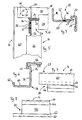
- a frame 10 to be arranged horizontally is shown, which as both top and also as the bottom or bottom frame of a frame for a right and left usable Fire door is suitable.
- the frame 10 to be arranged horizontally in cross section essentially a Z-shaped shape.
- the Frame to be arranged horizontally consists of two sub-elements, namely an angle 18 and an additional profile 20, which overlaps with a wide strip on a first leg 22 of the Angle 18 is arranged and thus has an overlap area 24.
- the rest of the area of the additional profile 20 has a Z-shaped reinforcing stop profile 26 and one then, as a stop bar 28 for the fire protection door, not shown trained flange.
- a sealing groove 27 is provided in the stop profile 26 Recording a door seal (not shown) is formed.
- Both the first leg 22 of the Angle 18 as well as for attachment to the masonry delimiting a door opening or the corresponding base area provided second legs 30 point on the extreme end 32 of the end region 12 each have a tab 34, 36. In both tabs 34, 36 are welded 38 in the vicinity of two diagonally opposite corners.
- a first tab 34 is formed by notching the second leg 30. That is, the first tab 34 is an extension of this second which is somewhat smaller in width Leg 30. As shown in FIG. 3 in connection with FIG.
- the first tab 34 is Z-shaped bent inwards towards the additional profile 20 in such a way that they approximately but not completely parallel to the first leg 30. It is through the Z-shaped Bending a shoulder 40 for engaging a corresponding area of the side frame 14 educated.
- the second tab 36 is also by disengaging the first leg 22 formed and is thus a smaller extension of this second Leg 22. As can be seen from FIG. 1, the second tab 36 is bent downward, however not by a full 90 °.
- the angle 18 and the additional profile 20 are at an edge 44 of the overlap area 24 with one another connected that predetermined breaking points 42 are created at which the two parts or Sub-elements 18, 20 can be broken apart.
- the edge 44 is on some Joints 46 (see Fig. 4) have been processed by means of an embossing stamp in such a way that Embossments (impressions, expressions) or expressions 48 are formed.
- the material of the additional profile 20 has been pressed so that it on this Junctions 46 is made thinner.
- the embossing also causes the material protrudes beyond the edge 44. Punctual connections are there on edge 44 pressed out connection points 46 by two first welding spots 50 as in FIG. 2 or a first weld spot 50, as shown in FIG. 9, per connection point 46 created.
- a spot spot can also be used Welding may be provided in the form of a short weld. Especially for education Such a weld seam is, for example, a long boss 47 at the connection point 46 as provided in DIN 8519. At these point connections or The predetermined breaking points 42 are formed in welding spots 50.
- the welding nipples 38 are used to create second welding spots 72 for tight welding the tabs 34, 36 provided on the side frame 14.
- the side frame 14 is, as in FIG. 6 shown, very similar in cross section to the frame 10 to be arranged horizontally, unlike this, however, from a single piece, for example by bending, folding or Rolls shaped. Accordingly, the side frame 14 has one of a first leg 56 and a second leg 60 existing angular range 58, with the first leg 56 a web 62 is additionally arranged. As an extension of the first leg 56 closes a Z-shaped reinforcement profile or stop profile 64 with a Sealing groove 65 on.
- the stop profile 64 also has the stop profile, by the way 26 a rear stop, which is used to fix the frame on Masonry is useful.
- the stop profiling 64 goes at the angular range 58 opposite end into a stop bar 66.
- a stop bar 66 As can be seen from FIGS. 7 and 8, form the first leg 56, the Z-shaped stop profile 64 and the stop bar 66 at the end 68 provided for forming the frame corner 16, a recess 70 into which the horizontally arranged frame 10 can engage with its stop bar 28.
- a recess 70 into which the horizontally arranged frame 10 can engage with its stop bar 28.
- the stop bar 28 of the frame 10 to be arranged horizontally has such a recess for engaging the corresponding one Part of the side frame 14.
- the formation of the frame corner 16 is explained below with reference to FIG. 5.
- the frame 10 to be arranged horizontally is placed on the side frame 14 as shown, wherein the stop bar 28 engages in the recess 70 so that from the side of the stop bars 66, 28 no gap remains.
- the first tab 34 is secured to the weld nipples 38 weld spots 72 applied to the second leg 60 of the side frame 14 selectively connected.
- the second tab 36 is attached to the welding nipples 38 Weld spots 72 are connected to the first leg 56 of the side frame 14.
- the first Tab 34 thus serves to arrange the second legs 30 and 60 to be arranged parallel to one another connect with each other.
- the second tab 36 provides a corner connection for the first Legs 22, 56 of the frames 10 and 14.
- the final position of the tabs 34, 36 parallel or perpendicular to the respective leg 30 or 22 of the angle 18 is only when welding achieved. Before welding, the tabs 34 and 36 lie on the legs 60 and 56 of the Side frame 14 only at the tips of the weld nipples 38 or one of them.
- the so created corner connection 54 can be separated again by sawing or flexing, whereby, if necessary, the entire frame 10 to be arranged horizontally from the rest of the Frame frame can be removed.
- a breakable frame part in the form of the additional profile 20 on the horizontal to be arranged frame 10 is provided, which at the predetermined breaking points 42 of the remaining Rest of the frame 10 to be arranged horizontally, ie. the angle 18, are canceled can.
- connections 54 and 46 are a frame for one on the right and fire protection door that can be used on the left, in which all connections are made Spot welding can be made.
- spot welding or Weld spots 50 or by means of short weld seams made on the long boss 47 predetermined breaking points 42 are created between the two sub-elements 18, 20 of the frame 10, on which frame parts can be broken off from the spot welded frame frame if necessary are.
- the spot welds also make galvanized materials from which the Frames 14, 10 preferably exist, can be firmly connected to one another.
- galvanized materials For example, inert gas welding would only lead to unsatisfactory connections. At point expansion of the welds, it is particularly easy to apply high pressures to the materials to be welded for welding, since they are comparatively low Forces must be used.
- the predetermined breaking points (42) are created in the area of a frame (10) to be arranged horizontally are on which an unwanted frame part (20) for certain installation situations from the Rest (10) of the frame frame can be broken off.
- the predetermined breaking points (42) are realized in that the connections between the frame parts (18, 20), from which the Frame frame is composed, preferably by means of spot welding or Spot welds (50) are formed at certain points.
- At least one of the horizontal ones Frames (10) consist of two sub-elements (18, 20) that are fixed to each other are connected to break apart.
- the selective connections attack in one Region of an edge (44) of one of the partial elements (20) formed expressions (48) which the material of this sub-element (20) is made thinner than in the rest Areas.
- the material at these expressions (48) is preferably over the edge (44) driven out.
Landscapes
- Engineering & Computer Science (AREA)
- Civil Engineering (AREA)
- Structural Engineering (AREA)
- Mechanical Engineering (AREA)
- Special Wing (AREA)
- Joining Of Corner Units Of Frames Or Wings (AREA)
Applications Claiming Priority (2)
| Application Number | Priority Date | Filing Date | Title |
|---|---|---|---|
| DE29803812U DE29803812U1 (de) | 1998-03-04 | 1998-03-04 | Zargenrahmen für eine Tür, insbesondere eine Feuerschutztür |
| DE29803812U | 1998-03-04 |
Publications (3)
| Publication Number | Publication Date |
|---|---|
| EP0940547A2 true EP0940547A2 (fr) | 1999-09-08 |
| EP0940547A3 EP0940547A3 (fr) | 2000-10-04 |
| EP0940547B1 EP0940547B1 (fr) | 2003-06-04 |
Family
ID=8053583
Family Applications (1)
| Application Number | Title | Priority Date | Filing Date |
|---|---|---|---|
| EP99104284A Expired - Lifetime EP0940547B1 (fr) | 1998-03-04 | 1999-03-03 | Cadre dormant pour porte, notamment une porte coupe-feu |
Country Status (7)
| Country | Link |
|---|---|
| EP (1) | EP0940547B1 (fr) |
| AT (1) | ATE242402T1 (fr) |
| DE (2) | DE29803812U1 (fr) |
| DK (1) | DK0940547T3 (fr) |
| ES (1) | ES2195460T3 (fr) |
| PL (1) | PL192127B1 (fr) |
| PT (1) | PT940547E (fr) |
Cited By (2)
| Publication number | Priority date | Publication date | Assignee | Title |
|---|---|---|---|---|
| KR100414645B1 (ko) * | 2000-04-12 | 2004-01-13 | 김찬근 | 스포트 크린칭으로 결합된 출입용 도어의 문틀결합구조 |
| EP4089259A2 (fr) | 2021-05-12 | 2022-11-16 | Sommer Fassadensysteme-Stahlbau-Sicherheitstechnik GmbH & Co. KG | Dispositif de fermeture permettant de séparer thermiquement des ouvertures de bâtiment ou d'espaces |
Families Citing this family (1)
| Publication number | Priority date | Publication date | Assignee | Title |
|---|---|---|---|---|
| CH711294A1 (de) * | 2015-07-06 | 2017-01-13 | Keller Zargen Ag | Anordnung zur Befestigung einer Zarge. |
Family Cites Families (7)
| Publication number | Priority date | Publication date | Assignee | Title |
|---|---|---|---|---|
| DE2062796C3 (de) * | 1970-12-19 | 1980-08-21 | Eisenwerk Kuenstler Kg, 8750 Aschaffenburg | Eckverbindung zweier verzinkter Einzelprofile eines Fensterrahmens o.dgl. und Verfahren zur Herstellung |
| DE2500862C3 (de) * | 1975-01-10 | 1978-06-22 | Podszuck Gmbh & Co Kg, 2300 Kiel | Rahmenförmige Metallzarge für Feuerschutztüren |
| DE2654822C3 (de) * | 1976-12-03 | 1981-09-17 | Alois 8411 Winkerling Schmid | Tür, insbesondere Stalltür |
| DE2821235C2 (de) * | 1978-05-16 | 1980-01-24 | Hoermann Kg Amshausen, 4803 Steinhagen | Türzarge |
| DE2947509A1 (de) * | 1979-11-24 | 1981-05-27 | Podszuck Gmbh & Co Kg, 2300 Kiel | Tuer mit einem seitlich und oben ueberfaelzten und unten stumpfen tuerblatt |
| DE8116322U1 (de) * | 1981-06-02 | 1982-03-11 | Favorit Türenwerke GmbH & Co KG, 4154 Tönisvorst | Tuerzarge aus metall |
| DE29700542U1 (de) * | 1997-01-14 | 1997-02-20 | Novoferm GmbH, 46459 Rees | Feuerschutztür |
-
1998
- 1998-03-04 DE DE29803812U patent/DE29803812U1/de not_active Expired - Lifetime
-
1999
- 1999-03-03 DE DE59905781T patent/DE59905781D1/de not_active Expired - Lifetime
- 1999-03-03 DK DK99104284T patent/DK0940547T3/da active
- 1999-03-03 AT AT99104284T patent/ATE242402T1/de active
- 1999-03-03 PL PL331727A patent/PL192127B1/pl unknown
- 1999-03-03 PT PT99104284T patent/PT940547E/pt unknown
- 1999-03-03 ES ES99104284T patent/ES2195460T3/es not_active Expired - Lifetime
- 1999-03-03 EP EP99104284A patent/EP0940547B1/fr not_active Expired - Lifetime
Non-Patent Citations (1)
| Title |
|---|
| None |
Cited By (3)
| Publication number | Priority date | Publication date | Assignee | Title |
|---|---|---|---|---|
| KR100414645B1 (ko) * | 2000-04-12 | 2004-01-13 | 김찬근 | 스포트 크린칭으로 결합된 출입용 도어의 문틀결합구조 |
| EP4089259A2 (fr) | 2021-05-12 | 2022-11-16 | Sommer Fassadensysteme-Stahlbau-Sicherheitstechnik GmbH & Co. KG | Dispositif de fermeture permettant de séparer thermiquement des ouvertures de bâtiment ou d'espaces |
| DE102021204810A1 (de) | 2021-05-12 | 2022-11-17 | Sommer Fassadensysteme-Stahlbau-Sicherheitstechnik Gmbh & Co. Kg | Verschlussvorrichtung zur thermischen Trennung von Gebäudeöffnungen oder Räumen |
Also Published As
| Publication number | Publication date |
|---|---|
| PT940547E (pt) | 2003-10-31 |
| DK0940547T3 (da) | 2003-09-29 |
| EP0940547B1 (fr) | 2003-06-04 |
| PL192127B1 (pl) | 2006-09-29 |
| ES2195460T3 (es) | 2003-12-01 |
| EP0940547A3 (fr) | 2000-10-04 |
| DE29803812U1 (de) | 1999-07-08 |
| DE59905781D1 (de) | 2003-07-10 |
| PL331727A1 (en) | 1999-09-13 |
| ATE242402T1 (de) | 2003-06-15 |
Similar Documents
| Publication | Publication Date | Title |
|---|---|---|
| DE3428179C2 (fr) | ||
| EP0308715A2 (fr) | Armoire électrique | |
| DE20307769U1 (de) | Balkenschuh | |
| DE4132803C2 (fr) | ||
| EP0940550B1 (fr) | Dormant et methode pour la construction d'un dormant | |
| EP0940547B1 (fr) | Cadre dormant pour porte, notamment une porte coupe-feu | |
| DE2460402B2 (de) | Ausstellvorrichtung für Drehkippflügel von Fenstern, Türen o.dgl. | |
| DE3706315C3 (de) | Schrank | |
| DE3939421C1 (fr) | ||
| DE4408346A1 (de) | Türflügel für ein Gebäude o. dgl. und Verfahren zum Herstellen eines Türflügels | |
| EP1076793B1 (fr) | Combinaison d'un element d'assemblage et de deux profils allonges | |
| EP0010291B1 (fr) | Armoire électrique | |
| EP1550786B1 (fr) | Dormant, notamment pour porte | |
| DE3500423A1 (de) | Scharnier, insbesondere fuer moebel | |
| EP1869278B1 (fr) | Profilé composite et méthode de fabrication de profilé composite pour cadres d'éléments de paroi, portes et fenêtres | |
| EP1067269A1 (fr) | Porte, notamment une porte coupe-feu | |
| WO1993011978A1 (fr) | Bras d'essuie-glace, notamment pour nettoyer les vitres de vehicules a moteur | |
| DE3307578A1 (de) | Eckverbinder | |
| DE3346624A1 (de) | Tuerfutter aus metall, profilblechstueck und verfahren zu seiner herstellung | |
| DE2448689B2 (de) | Scharnierarm aus metallblech | |
| DE2431367C2 (de) | Türzarge aus Metall | |
| EP0860570B1 (fr) | Elément de palier de battant | |
| EP0426950B1 (fr) | Pièce profilée pour un canal en tôle | |
| DE202007008202U1 (de) | Rahmengestell für einen Schaltschrank und Eckverbinder | |
| DE29715049U1 (de) | Anschlußelement |
Legal Events
| Date | Code | Title | Description |
|---|---|---|---|
| PUAI | Public reference made under article 153(3) epc to a published international application that has entered the european phase |
Free format text: ORIGINAL CODE: 0009012 |
|
| AK | Designated contracting states |
Kind code of ref document: A2 Designated state(s): AT BE CH CY DE DK ES FI FR GB GR IE IT LI LU MC NL PT SE |
|
| AX | Request for extension of the european patent |
Free format text: AL;LT;LV;MK;RO;SI |
|
| PUAL | Search report despatched |
Free format text: ORIGINAL CODE: 0009013 |
|
| AK | Designated contracting states |
Kind code of ref document: A3 Designated state(s): AT BE CH CY DE DK ES FI FR GB GR IE IT LI LU MC NL PT SE |
|
| AX | Request for extension of the european patent |
Free format text: AL;LT;LV;MK;RO;SI |
|
| 17P | Request for examination filed |
Effective date: 20001023 |
|
| AKX | Designation fees paid |
Free format text: AT BE CH CY DE DK ES FI FR GB GR IE IT LI LU MC NL PT SE |
|
| AXX | Extension fees paid |
Free format text: SI PAYMENT 20001023 |
|
| 17Q | First examination report despatched |
Effective date: 20020513 |
|
| GRAH | Despatch of communication of intention to grant a patent |
Free format text: ORIGINAL CODE: EPIDOS IGRA |
|
| GRAH | Despatch of communication of intention to grant a patent |
Free format text: ORIGINAL CODE: EPIDOS IGRA |
|
| GRAA | (expected) grant |
Free format text: ORIGINAL CODE: 0009210 |
|
| RAP1 | Party data changed (applicant data changed or rights of an application transferred) |
Owner name: HOERMANN KG BRANDIS |
|
| AK | Designated contracting states |
Designated state(s): AT BE CH CY DE DK ES FI FR GB GR IE IT LI LU MC NL PT SE |
|
| AX | Request for extension of the european patent |
Extension state: SI |
|
| PG25 | Lapsed in a contracting state [announced via postgrant information from national office to epo] |
Ref country code: CY Free format text: LAPSE BECAUSE OF FAILURE TO SUBMIT A TRANSLATION OF THE DESCRIPTION OR TO PAY THE FEE WITHIN THE PRESCRIBED TIME-LIMIT Effective date: 20030604 |
|
| REG | Reference to a national code |
Ref country code: GB Ref legal event code: FG4D Free format text: NOT ENGLISH |
|
| REG | Reference to a national code |
Ref country code: CH Ref legal event code: NV Representative=s name: PATENTANWALTSBUERO DR. URS FALK Ref country code: CH Ref legal event code: EP |
|
| REG | Reference to a national code |
Ref country code: IE Ref legal event code: FG4D Free format text: GERMAN |
|
| REF | Corresponds to: |
Ref document number: 59905781 Country of ref document: DE Date of ref document: 20030710 Kind code of ref document: P |
|
| REG | Reference to a national code |
Ref country code: SE Ref legal event code: TRGR |
|
| REG | Reference to a national code |
Ref country code: GR Ref legal event code: EP Ref document number: 20030403178 Country of ref document: GR |
|
| REG | Reference to a national code |
Ref country code: DK Ref legal event code: T3 |
|
| GBT | Gb: translation of ep patent filed (gb section 77(6)(a)/1977) |
Effective date: 20031008 |
|
| PG25 | Lapsed in a contracting state [announced via postgrant information from national office to epo] |
Ref country code: MC Free format text: LAPSE BECAUSE OF NON-PAYMENT OF DUE FEES Effective date: 20040331 |
|
| ET | Fr: translation filed | ||
| PLBE | No opposition filed within time limit |
Free format text: ORIGINAL CODE: 0009261 |
|
| STAA | Information on the status of an ep patent application or granted ep patent |
Free format text: STATUS: NO OPPOSITION FILED WITHIN TIME LIMIT |
|
| 26N | No opposition filed |
Effective date: 20040305 |
|
| PGFP | Annual fee paid to national office [announced via postgrant information from national office to epo] |
Ref country code: PT Payment date: 20100219 Year of fee payment: 12 Ref country code: LU Payment date: 20100312 Year of fee payment: 12 Ref country code: DK Payment date: 20100326 Year of fee payment: 12 |
|
| PGFP | Annual fee paid to national office [announced via postgrant information from national office to epo] |
Ref country code: GB Payment date: 20100222 Year of fee payment: 12 |
|
| PGFP | Annual fee paid to national office [announced via postgrant information from national office to epo] |
Ref country code: IE Payment date: 20100420 Year of fee payment: 12 |
|
| PGFP | Annual fee paid to national office [announced via postgrant information from national office to epo] |
Ref country code: NL Payment date: 20100330 Year of fee payment: 12 Ref country code: BE Payment date: 20100329 Year of fee payment: 12 |
|
| PGFP | Annual fee paid to national office [announced via postgrant information from national office to epo] |
Ref country code: GR Payment date: 20100226 Year of fee payment: 12 |
|
| REG | Reference to a national code |
Ref country code: PT Ref legal event code: MM4A Free format text: LAPSE DUE TO NON-PAYMENT OF FEES Effective date: 20110905 |
|
| BERE | Be: lapsed |
Owner name: *HORMANN K.G. BRANDIS Effective date: 20110331 |
|
| REG | Reference to a national code |
Ref country code: NL Ref legal event code: V1 Effective date: 20111001 |
|
| PG25 | Lapsed in a contracting state [announced via postgrant information from national office to epo] |
Ref country code: PT Free format text: LAPSE BECAUSE OF NON-PAYMENT OF DUE FEES Effective date: 20110905 |
|
| REG | Reference to a national code |
Ref country code: DK Ref legal event code: EBP |
|
| GBPC | Gb: european patent ceased through non-payment of renewal fee |
Effective date: 20110303 |
|
| PG25 | Lapsed in a contracting state [announced via postgrant information from national office to epo] |
Ref country code: BE Free format text: LAPSE BECAUSE OF NON-PAYMENT OF DUE FEES Effective date: 20110331 |
|
| REG | Reference to a national code |
Ref country code: IE Ref legal event code: MM4A |
|
| PG25 | Lapsed in a contracting state [announced via postgrant information from national office to epo] |
Ref country code: NL Free format text: LAPSE BECAUSE OF NON-PAYMENT OF DUE FEES Effective date: 20111001 Ref country code: IE Free format text: LAPSE BECAUSE OF NON-PAYMENT OF DUE FEES Effective date: 20110303 |
|
| PG25 | Lapsed in a contracting state [announced via postgrant information from national office to epo] |
Ref country code: GB Free format text: LAPSE BECAUSE OF NON-PAYMENT OF DUE FEES Effective date: 20110303 Ref country code: GR Free format text: LAPSE BECAUSE OF NON-PAYMENT OF DUE FEES Effective date: 20111004 |
|
| PG25 | Lapsed in a contracting state [announced via postgrant information from national office to epo] |
Ref country code: DK Free format text: LAPSE BECAUSE OF NON-PAYMENT OF DUE FEES Effective date: 20110331 |
|
| PG25 | Lapsed in a contracting state [announced via postgrant information from national office to epo] |
Ref country code: LU Free format text: LAPSE BECAUSE OF NON-PAYMENT OF DUE FEES Effective date: 20110303 |
|
| REG | Reference to a national code |
Ref country code: DE Ref legal event code: R082 Ref document number: 59905781 Country of ref document: DE Representative=s name: KASTEL PATENTANWAELTE PARTG MBB, DE Ref country code: DE Ref legal event code: R082 Ref document number: 59905781 Country of ref document: DE Representative=s name: KASTEL PATENTANWAELTE, DE |
|
| REG | Reference to a national code |
Ref country code: FR Ref legal event code: PLFP Year of fee payment: 18 |
|
| REG | Reference to a national code |
Ref country code: FR Ref legal event code: PLFP Year of fee payment: 19 |
|
| REG | Reference to a national code |
Ref country code: FR Ref legal event code: PLFP Year of fee payment: 20 |
|
| PGFP | Annual fee paid to national office [announced via postgrant information from national office to epo] |
Ref country code: FI Payment date: 20180320 Year of fee payment: 20 Ref country code: CH Payment date: 20180326 Year of fee payment: 20 |
|
| REG | Reference to a national code |
Ref country code: CH Ref legal event code: PCAR Free format text: NEW ADDRESS: HOLEESTRASSE 87, 4054 BASEL (CH) |
|
| PGFP | Annual fee paid to national office [announced via postgrant information from national office to epo] |
Ref country code: FR Payment date: 20180326 Year of fee payment: 20 Ref country code: AT Payment date: 20180320 Year of fee payment: 20 Ref country code: IT Payment date: 20180322 Year of fee payment: 20 Ref country code: SE Payment date: 20180326 Year of fee payment: 20 |
|
| PGFP | Annual fee paid to national office [announced via postgrant information from national office to epo] |
Ref country code: DE Payment date: 20180516 Year of fee payment: 20 Ref country code: ES Payment date: 20180423 Year of fee payment: 20 |
|
| REG | Reference to a national code |
Ref country code: DE Ref legal event code: R071 Ref document number: 59905781 Country of ref document: DE |
|
| REG | Reference to a national code |
Ref country code: CH Ref legal event code: PL |
|
| REG | Reference to a national code |
Ref country code: AT Ref legal event code: MK07 Ref document number: 242402 Country of ref document: AT Kind code of ref document: T Effective date: 20190303 |
|
| REG | Reference to a national code |
Ref country code: ES Ref legal event code: FD2A Effective date: 20200724 |
|
| PG25 | Lapsed in a contracting state [announced via postgrant information from national office to epo] |
Ref country code: ES Free format text: LAPSE BECAUSE OF EXPIRATION OF PROTECTION Effective date: 20190304 |