EP0940553A2 - Betätigungsvorrichtung für einen Rollvorhang - Google Patents
Betätigungsvorrichtung für einen Rollvorhang Download PDFInfo
- Publication number
- EP0940553A2 EP0940553A2 EP98830448A EP98830448A EP0940553A2 EP 0940553 A2 EP0940553 A2 EP 0940553A2 EP 98830448 A EP98830448 A EP 98830448A EP 98830448 A EP98830448 A EP 98830448A EP 0940553 A2 EP0940553 A2 EP 0940553A2
- Authority
- EP
- European Patent Office
- Prior art keywords
- blind
- crown
- roller
- supporting structure
- driving pulley
- Prior art date
- Legal status (The legal status is an assumption and is not a legal conclusion. Google has not performed a legal analysis and makes no representation as to the accuracy of the status listed.)
- Granted
Links
Images



Classifications
-
- E—FIXED CONSTRUCTIONS
- E06—DOORS, WINDOWS, SHUTTERS, OR ROLLER BLINDS IN GENERAL; LADDERS
- E06B—FIXED OR MOVABLE CLOSURES FOR OPENINGS IN BUILDINGS, VEHICLES, FENCES OR LIKE ENCLOSURES IN GENERAL, e.g. DOORS, WINDOWS, BLINDS, GATES
- E06B9/00—Screening or protective devices for wall or similar openings, with or without operating or securing mechanisms; Closures of similar construction
- E06B9/56—Operating, guiding or securing devices or arrangements for roll-type closures; Spring drums; Tape drums; Counterweighting arrangements therefor
- E06B9/78—Operating, guiding or securing devices or arrangements for roll-type closures; Spring drums; Tape drums; Counterweighting arrangements therefor for direct manual operation, e.g. by tassels, by handles
Definitions
- the present invention relates to devices for actuating roller blinds, of the type comprising:
- the object of the present invention is that of providing a device for actuating roller blinds of the above indicated type which is able to satisfy both the above indicated needs in the best possible way.
- the device according to the invention is characterized in that said driving transmission includes an epicyclic gear train comprising:
- the device according to the invention has an auxiliary element which can be mounted in two different conditions for providing the two above mentioned operative conditions of the toothed crown of the epicyclic gear unit.
- This auxiliary element is constituted by a disk which in both of its operative conditions is rigidly connected to the above mentioned toothed crown by means of mating shaped surfaces. In a first operative condition of said disk, the latter has one of its front faces having respective engaging elements fitted within cooperating seats of the fixed supporting structure, so that in this condition the toothed crown is in its operative condition corresponding to the activation of the reducing unit.
- the above mentioned auxiliary disk can be mounted with its front face facing towards the opposite direction, but still being engaged with the toothed crown, with the above mentioned engaging elements fitted between the solar sprocket and the planets, so that the toothed crown is free to rotate, but forms a whole unit with the solar sprocket and the planets, so that the direct drive transmission is activated.
- the device according to the invention can be used both with very heavy blinds, in which it is paramount to make actuation by the user easier, and with blinds of reduced weight, in which it is most important to render the raising operation of the blind as much rapid as possible.
- the operator which mounts the blind can adapt the device to the two above mentioned conditions simply by assembling the above mentioned auxiliary disk with said front face facing towards one direction or the other, thus obtaining the actuation either of the reducing unit or the direct drive transmission. Therefore, the manufacturer can put a single type of device into production, with clear advantages from the point of view of rationalisation of production and storing.
- the above mentioned driving transmission is provided with a pair of gears, one of which is connected in rotation to the blind roller, said two gears having a number of teeth different from each other and being provided with two respective engaging elements which come into contact with each other after a predetermined number of turns of the above mentioned gears, so as to prevent a further rotation thereof, these engaging elements being arranged so as to stop the movement of the blind roller when the blind web is in a lowered predetermined condition.
- this condition is predetermined as corresponding to a not fully unwound condition of the blind web from the roller, so as to avoid that the user, when driving lowering of the web, may cause a new winding of the web in the opposite direction or even separation of the web from the roller.
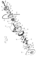
- reference numeral 1 generally designates a roller blind, comprising a fixed supporting structure which, in the illustrated example, is constituted by two end brackets 2, 3 which are to be fixed to a ceiling or a wall, for instance adjacent to a window.
- the supporting bracket 2 has a body of plastic material including a vertical wall 4 to which there is secured, by tight fit of teeth 5 into respective seats of wall 4, an annular plate 6 including a roof-like element 7 which is to prevent a ball chain 8 from coming out of a driving pulley 9, which will be described in detail in the following.
- the ball chain 8 hanks downwardly to a height which can be easily reached by the user to enable him to actuate the blind.
- Spring 10 in its undeformed condition has an inner diameter lower than the outer diameter of the fixed hub 4a, so that once it is mounted around hub 4a it is held tightened on this hub by its proper elasticity.
- ring section 11 which in the illustrated example is made of zama, around which there is rotatably mounted the driving pulley 9 actuated by the ball chain 8.
- the driving pulley 9 has an inner tooth 12 projecting radially inwardly on which there is fitted a U-shaped element 13 which extends axially at least throughout the whole axial dimension of spring 10 and is arranged circumferentially within the space between the two end tails 10a of spring 10, as clearly shown in figure 5.
- the ring section 11 is rigidly connected to a wheel 14 by engagement of two front teeth 15 into cooperating notches 16 of wheel 14.
- wheel 14 is rigidly connected to hub 17 of a planet carrying wheel 18, which will be described in detail in the following, by coupling of front teeth of hub 17 into cooperating seats 19 of wheel 14.
- a blind web W is wound around a roller R which is rigidly mounted onto one end 20a of a shaft 20.
- Shaft 20 is freely rotatable within the hub 17 of wheel 18 and has an opposite end 20b on which there is fitted a solar sprocket 21 of an epicyclic gear unit 22 which will be described in the following, the above mentioned unit being held axially by means of an elastic ring 23 fitted onto the end 20b of shaft 20.
- the hub 17 of wheel 18 is rotatably mounted within the fixed hub 4a by interposition of a bush of plastic material 24 (see figure 3).
- the epicyclic gear train 22 comprises the solar sprocket 21 connected in rotation to shaft 20, a plurality of planet gears 25 meshing with solar sprocket 21 and freely rotatably mounted on pins 26 of the planet carrying wheel 18 which is connected in rotation to wheel 14 and which, as it will be clearly apparent, is to be driven by pulley 9.
- the epicyclic gear train 22 has an outer crown 27, having inner teeth 28, which in the illustrated example has a cylindrical annular body.
- the crown 27 is freely rotatable within seat 29 of the fixed structure 2 and is rigidly connected to an auxiliary disk 30 by mating shaped elements, namely by engagement of radial teeth 31 distributed along the peripheral disk 30 within cooperating front notches 32 of crown 27.
- the auxiliary disk 30 has one of its front faces having engaging elements 33 facing towards a lid 34 which is fitted on the vertical wall 4 of the fixed structure 2.
- the engaging elements 33 are received within cooperating seats 35, so that the auxiliary disk 30 is rigidly connected to the fixed structure 2 and therefore rigidly connects also the outer crown 27 to this structure. Therefore, in this condition the epicyclic gear train 22 is able to act as a reducing gear unit by transmitting rotation from the planet carrying wheel 18 to the solar sprocket 21 rigidly connected to the shaft 20 of the blind roller (see also figure 4).
- Figures 6, 8 refer to a variant in which the device comprises additional stop means for the blind web in the position of maximum lowering.
- the seats 35 for the engaging elements 33 of the auxiliary disk 30 are formed, rather than in lid 34, in an intermediate plate 36 interposed between the disk 30 and the lid 34.
- the latter further supports a pair of freely rotatable gears 37, 38.
- Gear 38 is fitted on the end 20b of shaft 20 of the blind roller, so that it always rotates along with the blind roller.
- the two gears 37, 38 have numbers of teeth different from each other by 1 and are provided with two respective locking elements 39, 40 (figure 8) which collide with each other when the web reaches the lowermost position, so as to stop it.
- the two locking elements 39, 40 can be arranged so as to stop the blind web when it has not been fully unwound from the roller, so as to leave at least two-three turns of cloth around the roller which ensure both the subsequent proper winding back of the web, and the impossibility of a separation of the web from the roller.
- the device according to the invention is characterized by a relatively simple and inexpensive structure, which at the same time is able to be adapted easily and rapidly at the time of installation so as to allow either actuation through a reducing gear unit (when it is necessary to decrease the effort for the user, with heavy blinds) or the actuation with direct drive (when it is necessary to favour rapidity of operation).
- the stop means constituted by the two gears 37, 38 further improve the device.
Landscapes
- Engineering & Computer Science (AREA)
- Structural Engineering (AREA)
- Architecture (AREA)
- Civil Engineering (AREA)
- Operating, Guiding And Securing Of Roll- Type Closing Members (AREA)
- Rolls And Other Rotary Bodies (AREA)
- Motorcycle And Bicycle Frame (AREA)
Applications Claiming Priority (2)
| Application Number | Priority Date | Filing Date | Title |
|---|---|---|---|
| ITTO980186 | 1998-03-06 | ||
| ITTO980186 ITTO980186A1 (it) | 1998-03-06 | 1998-03-06 | Dispositivo di comando per una tenda a rullo. |
Publications (3)
| Publication Number | Publication Date |
|---|---|
| EP0940553A2 true EP0940553A2 (de) | 1999-09-08 |
| EP0940553A3 EP0940553A3 (de) | 2001-08-01 |
| EP0940553B1 EP0940553B1 (de) | 2003-03-26 |
Family
ID=11416537
Family Applications (1)
| Application Number | Title | Priority Date | Filing Date |
|---|---|---|---|
| EP19980830448 Expired - Lifetime EP0940553B1 (de) | 1998-03-06 | 1998-07-23 | Betätigungsvorrichtung für einen Rollvorhang |
Country Status (4)
| Country | Link |
|---|---|
| EP (1) | EP0940553B1 (de) |
| DE (1) | DE69812582T2 (de) |
| ES (1) | ES2192319T3 (de) |
| IT (1) | ITTO980186A1 (de) |
Cited By (12)
| Publication number | Priority date | Publication date | Assignee | Title |
|---|---|---|---|---|
| GB2392703A (en) * | 2003-08-19 | 2004-03-10 | Louver Lite Ltd | Roller blind control unit |
| AU2004200411C1 (en) * | 2003-08-19 | 2004-03-25 | Louver-Lite Limited | Improvements in control units |
| GB2430225A (en) * | 2005-09-14 | 2007-03-21 | Tai-Ping Liu | Roller blind drive mechanism |
| EP1717399A3 (de) * | 2002-03-20 | 2008-04-09 | Rollease, Inc. | Kupplung mit innenliegendem Getriebe für einen Rollvorhang |
| WO2008063566A3 (en) * | 2006-11-16 | 2008-10-09 | Lutron Electronics Co | Manual roller shade having clutch mechanism, chain guide and universal mounting |
| WO2012016486A1 (zh) * | 2010-08-06 | 2012-02-09 | 广州市伽瑞窗饰制品有限公司 | 一种拉珠卷帘制头 |
| WO2013052084A1 (en) * | 2011-10-03 | 2013-04-11 | Hunter Douglas Inc. | Control of architectural opening coverings |
| US9399888B2 (en) | 2013-03-14 | 2016-07-26 | Hunter Douglas, Inc. | Methods and apparatus to control an architectural opening covering assembly |
| US9790739B2 (en) | 2010-05-28 | 2017-10-17 | Hunter Douglas Inc. | Architectural opening coverings powered by rotary motors |
| EP3323976A3 (de) * | 2016-10-26 | 2018-09-12 | Hunter Douglas Inc. | Bedienungssystem für eine architektonische abdeckung |
| US10648232B2 (en) | 2012-10-03 | 2020-05-12 | Hunter Douglas Inc. | Methods and apparatus to control an architectural opening covering assembly |
| US11381860B2 (en) | 2014-12-31 | 2022-07-05 | The Nielsen Company (Us), Llc | Methods and apparatus to correct for deterioration of a demographic model to associate demographic information with media impression information |
Families Citing this family (2)
| Publication number | Priority date | Publication date | Assignee | Title |
|---|---|---|---|---|
| USD498635S1 (en) | 2003-08-27 | 2004-11-23 | Louver Lite Limited | Sprocket support for a blind |
| USD509092S1 (en) | 2003-08-27 | 2005-09-06 | Louver Lite Limited | Sprocket support for a blind |
Family Cites Families (3)
| Publication number | Priority date | Publication date | Assignee | Title |
|---|---|---|---|---|
| IT1158117B (it) * | 1982-06-09 | 1987-02-18 | Elvana Piemonte | Dispositivo a frizione per il sollevamento di avvolgibili |
| CH664420A5 (de) * | 1984-06-04 | 1988-02-29 | Schenker Emil Ag | Antrieb fuer die aufzugswelle eines stores. |
| FR2722183B1 (fr) * | 1994-07-11 | 1996-09-13 | Zurfluh Feller Sa | Treuil debrayable a cordon |
-
1998
- 1998-03-06 IT ITTO980186 patent/ITTO980186A1/it unknown
- 1998-07-23 ES ES98830448T patent/ES2192319T3/es not_active Expired - Lifetime
- 1998-07-23 DE DE1998612582 patent/DE69812582T2/de not_active Expired - Fee Related
- 1998-07-23 EP EP19980830448 patent/EP0940553B1/de not_active Expired - Lifetime
Cited By (42)
| Publication number | Priority date | Publication date | Assignee | Title |
|---|---|---|---|---|
| EP1717399A3 (de) * | 2002-03-20 | 2008-04-09 | Rollease, Inc. | Kupplung mit innenliegendem Getriebe für einen Rollvorhang |
| AU2004200411B2 (en) * | 2003-08-19 | 2004-03-25 | Louver-Lite Limited | Improvements in control units |
| GB2393203B (en) * | 2003-08-19 | 2004-08-11 | Louver Lite Ltd | Improvements in control units |
| GB2393203A (en) * | 2003-08-19 | 2004-03-24 | Louver Lite Ltd | Roller blind control |
| GB2392945B (en) * | 2003-08-19 | 2004-08-11 | Louver Lite Ltd | Improvements in control units |
| GB2392703A (en) * | 2003-08-19 | 2004-03-10 | Louver Lite Ltd | Roller blind control unit |
| AU2004200413B2 (en) * | 2003-08-19 | 2004-06-10 | Louver-Lite Limited | Improvements in control units |
| GB2392703B (en) * | 2003-08-19 | 2004-06-23 | Louver Lite Ltd | Improvements in control units |
| AU2004200412B2 (en) * | 2003-08-19 | 2004-07-01 | Louver-Lite Limited | Improvements in control units |
| GB2392946A (en) * | 2003-08-19 | 2004-03-17 | Louver Lite Ltd | Roller blind control unit |
| GB2392946B (en) * | 2003-08-19 | 2004-07-21 | Louver Lite Ltd | Improvements in control units |
| AU2004200411C1 (en) * | 2003-08-19 | 2004-03-25 | Louver-Lite Limited | Improvements in control units |
| US7100668B2 (en) | 2003-08-19 | 2006-09-05 | Louver-Lite Limited | Control units |
| GB2392945A (en) * | 2003-08-19 | 2004-03-17 | Louver Lite Ltd | Roller blind control unit |
| GB2430225B (en) * | 2005-09-14 | 2007-08-29 | Tai-Ping Liu | Shade roller capable of bearing heavy load |
| GB2430225A (en) * | 2005-09-14 | 2007-03-21 | Tai-Ping Liu | Roller blind drive mechanism |
| WO2008063566A3 (en) * | 2006-11-16 | 2008-10-09 | Lutron Electronics Co | Manual roller shade having clutch mechanism, chain guide and universal mounting |
| US10718159B2 (en) | 2010-05-28 | 2020-07-21 | Hunter Douglas Inc. | Architectural opening coverings powered by rotary motors |
| US9790739B2 (en) | 2010-05-28 | 2017-10-17 | Hunter Douglas Inc. | Architectural opening coverings powered by rotary motors |
| WO2012016486A1 (zh) * | 2010-08-06 | 2012-02-09 | 广州市伽瑞窗饰制品有限公司 | 一种拉珠卷帘制头 |
| CN103889281A (zh) * | 2011-10-03 | 2014-06-25 | 亨特道格拉斯公司 | 用于控制建筑开口覆盖物总成的方法和装置 |
| US9334688B2 (en) | 2011-10-03 | 2016-05-10 | Hunter Douglas Inc. | Control of architectural opening coverings |
| US10975619B2 (en) | 2011-10-03 | 2021-04-13 | Hunter Douglas Inc. | Methods and apparatus to control architectural opening covering assemblies |
| CN103890303B (zh) * | 2011-10-03 | 2016-08-24 | 亨特道格拉斯公司 | 建筑开口覆盖物的控制 |
| AU2012319162B2 (en) * | 2011-10-03 | 2017-03-09 | Hunter Douglas Inc. | Control of architectural opening coverings |
| US9765568B2 (en) | 2011-10-03 | 2017-09-19 | Hunter Douglas Inc. | Methods and apparatus to control architectural opening covering assemblies |
| CN103890303A (zh) * | 2011-10-03 | 2014-06-25 | 亨特道格拉斯公司 | 建筑开口覆盖物的控制 |
| WO2013052084A1 (en) * | 2011-10-03 | 2013-04-11 | Hunter Douglas Inc. | Control of architectural opening coverings |
| US10202802B2 (en) | 2011-10-03 | 2019-02-12 | Hunter Douglas Inc. | Control of architectural opening coverings |
| US10273751B2 (en) | 2011-10-03 | 2019-04-30 | Hunter Douglas Inc. | Methods and apparatus to control architectural opening covering assemblies |
| US10648232B2 (en) | 2012-10-03 | 2020-05-12 | Hunter Douglas Inc. | Methods and apparatus to control an architectural opening covering assembly |
| US10590701B2 (en) | 2013-03-14 | 2020-03-17 | Hunter Douglas Inc. | Methods and apparatus to control an architectural opening covering assembly |
| US9399888B2 (en) | 2013-03-14 | 2016-07-26 | Hunter Douglas, Inc. | Methods and apparatus to control an architectural opening covering assembly |
| US11377905B2 (en) | 2013-03-14 | 2022-07-05 | Hunter Douglas Inc. | Methods and apparatus to control an architectural opening covering assembly |
| US11381860B2 (en) | 2014-12-31 | 2022-07-05 | The Nielsen Company (Us), Llc | Methods and apparatus to correct for deterioration of a demographic model to associate demographic information with media impression information |
| US11983730B2 (en) | 2014-12-31 | 2024-05-14 | The Nielsen Company (Us), Llc | Methods and apparatus to correct for deterioration of a demographic model to associate demographic information with media impression information |
| US10407983B2 (en) | 2016-10-26 | 2019-09-10 | Hunter Douglas Inc. | Operating system for an architectural covering |
| EP3323976A3 (de) * | 2016-10-26 | 2018-09-12 | Hunter Douglas Inc. | Bedienungssystem für eine architektonische abdeckung |
| US10941614B2 (en) | 2016-10-26 | 2021-03-09 | Hunter Douglas Inc. | Operating system for an architectural covering |
| CN112943075A (zh) * | 2016-10-26 | 2021-06-11 | 亨特道格拉斯公司 | 用于建筑覆盖物的操作系统 |
| TWI777987B (zh) * | 2016-10-26 | 2022-09-21 | 美商漢特道格拉斯股份有限公司 | 用於建築覆蓋物之操作系統及方法 |
| KR20240074725A (ko) * | 2016-10-26 | 2024-05-28 | 헌터더글라스인코포레이티드 | 건축물 덮개를 위한 동작 시스템 |
Also Published As
| Publication number | Publication date |
|---|---|
| EP0940553A3 (de) | 2001-08-01 |
| ITTO980186A1 (it) | 1999-09-06 |
| DE69812582T2 (de) | 2004-01-29 |
| EP0940553B1 (de) | 2003-03-26 |
| DE69812582D1 (de) | 2003-04-30 |
| ES2192319T3 (es) | 2003-10-01 |
Similar Documents
| Publication | Publication Date | Title |
|---|---|---|
| EP0940553B1 (de) | Betätigungsvorrichtung für einen Rollvorhang | |
| EP2057342B1 (de) | Antriebs- und montagesystem für ein rollo | |
| US5542464A (en) | Roller blind with screen rolled up by a spring and rolled down by hand | |
| CA2452908C (en) | A roller shade clutch with internal gearing | |
| JP2005521816A (ja) | 操作機構及びかかる装置が組み入れられた閉鎖又は日除け設備 | |
| US4848433A (en) | Two-speed reducing mechanism for controlling closure devices with adjustable luminosity, of the type such as blinds with orientable slats and the like | |
| CA1166562A (en) | Electrically-operated roller door operating mechanism | |
| US5447477A (en) | Electric gear motor with epicycloidal reduction and automatic brake for supple shutters of the balanced type | |
| GB2562878B (en) | Geared bracket for a window shade | |
| EP2681392B1 (de) | Rollokupplung | |
| EP0868591B1 (de) | Antriebs-und befestigungsvorrichtung für ein rolltor | |
| CA2520781A1 (en) | Control units | |
| EA000118B1 (ru) | Управляющее приспособление для экранирующего устройства | |
| JP3727949B2 (ja) | ローラー・カーテンを巻き上げるための弾性手段 | |
| JP4750663B2 (ja) | ブラインドの昇降装置 | |
| EP0096664B1 (de) | Reibungseinrichtung zum Aufwickeln und Heben von Rolläden | |
| EP3902969B1 (de) | Betätigungsmechanismus für eine fensterabdeckung und fensterabdeckung | |
| EP1854954A2 (de) | Rouleaukupplung mit internem Getriebe | |
| GB2063358A (en) | Electrically-operated roller door mechanism | |
| JP3313494B2 (ja) | 電動機取付機構 | |
| US20220145698A1 (en) | Folding/unfolding device for a window shade | |
| JP3823430B2 (ja) | ブラインド装置 | |
| KR200254701Y1 (ko) | 블라인드의 어저스터 | |
| JPH0617998Y2 (ja) | 電動シヤツタのリミツト装置 | |
| HK1126265B (en) | Operating and mounting system for a window covering |
Legal Events
| Date | Code | Title | Description |
|---|---|---|---|
| PUAI | Public reference made under article 153(3) epc to a published international application that has entered the european phase |
Free format text: ORIGINAL CODE: 0009012 |
|
| AK | Designated contracting states |
Kind code of ref document: A2 Designated state(s): DE ES NL |
|
| AX | Request for extension of the european patent |
Free format text: AL;LT;LV;MK;RO;SI |
|
| PUAL | Search report despatched |
Free format text: ORIGINAL CODE: 0009013 |
|
| AK | Designated contracting states |
Kind code of ref document: A3 Designated state(s): AT BE CH CY DE DK ES FI FR GB GR IE IT LI LU MC NL PT SE |
|
| AX | Request for extension of the european patent |
Free format text: AL;LT;LV;MK;RO;SI |
|
| 17P | Request for examination filed |
Effective date: 20011204 |
|
| 17Q | First examination report despatched |
Effective date: 20020129 |
|
| AKX | Designation fees paid |
Free format text: DE ES NL |
|
| GRAH | Despatch of communication of intention to grant a patent |
Free format text: ORIGINAL CODE: EPIDOS IGRA |
|
| GRAH | Despatch of communication of intention to grant a patent |
Free format text: ORIGINAL CODE: EPIDOS IGRA |
|
| GRAA | (expected) grant |
Free format text: ORIGINAL CODE: 0009210 |
|
| AK | Designated contracting states |
Designated state(s): DE ES NL |
|
| REF | Corresponds to: |
Ref document number: 69812582 Country of ref document: DE Date of ref document: 20030430 Kind code of ref document: P |
|
| PGFP | Annual fee paid to national office [announced via postgrant information from national office to epo] |
Ref country code: ES Payment date: 20030611 Year of fee payment: 6 |
|
| PGFP | Annual fee paid to national office [announced via postgrant information from national office to epo] |
Ref country code: NL Payment date: 20030630 Year of fee payment: 6 |
|
| PGFP | Annual fee paid to national office [announced via postgrant information from national office to epo] |
Ref country code: DE Payment date: 20030918 Year of fee payment: 6 |
|
| REG | Reference to a national code |
Ref country code: ES Ref legal event code: FG2A Ref document number: 2192319 Country of ref document: ES Kind code of ref document: T3 |
|
| PLBE | No opposition filed within time limit |
Free format text: ORIGINAL CODE: 0009261 |
|
| STAA | Information on the status of an ep patent application or granted ep patent |
Free format text: STATUS: NO OPPOSITION FILED WITHIN TIME LIMIT |
|
| 26N | No opposition filed |
Effective date: 20031230 |
|
| PG25 | Lapsed in a contracting state [announced via postgrant information from national office to epo] |
Ref country code: ES Free format text: LAPSE BECAUSE OF NON-PAYMENT OF DUE FEES Effective date: 20040724 |
|
| PG25 | Lapsed in a contracting state [announced via postgrant information from national office to epo] |
Ref country code: NL Free format text: LAPSE BECAUSE OF NON-PAYMENT OF DUE FEES Effective date: 20050201 Ref country code: DE Free format text: LAPSE BECAUSE OF NON-PAYMENT OF DUE FEES Effective date: 20050201 |
|
| NLV4 | Nl: lapsed or anulled due to non-payment of the annual fee |
Effective date: 20050201 |
|
| REG | Reference to a national code |
Ref country code: ES Ref legal event code: FD2A Effective date: 20040724 |