EP0940554B1 - Dispositif de commande pour un volet à rouleau - Google Patents
Dispositif de commande pour un volet à rouleauInfo
- Publication number
- EP0940554B1 EP0940554B1 EP99104415A EP99104415A EP0940554B1 EP 0940554 B1 EP0940554 B1 EP 0940554B1 EP 99104415 A EP99104415 A EP 99104415A EP 99104415 A EP99104415 A EP 99104415A EP 0940554 B1 EP0940554 B1 EP 0940554B1
- Authority
- EP
- European Patent Office
- Prior art keywords
- end position
- roller blind
- drape
- user
- reached
- Prior art date
- Legal status (The legal status is an assumption and is not a legal conclusion. Google has not performed a legal analysis and makes no representation as to the accuracy of the status listed.)
- Expired - Lifetime
Links
Images



Classifications
-
- E—FIXED CONSTRUCTIONS
- E06—DOORS, WINDOWS, SHUTTERS, OR ROLLER BLINDS IN GENERAL; LADDERS
- E06B—FIXED OR MOVABLE CLOSURES FOR OPENINGS IN BUILDINGS, VEHICLES, FENCES OR LIKE ENCLOSURES IN GENERAL, e.g. DOORS, WINDOWS, BLINDS, GATES
- E06B9/00—Screening or protective devices for wall or similar openings, with or without operating or securing mechanisms; Closures of similar construction
- E06B9/56—Operating, guiding or securing devices or arrangements for roll-type closures; Spring drums; Tape drums; Counterweighting arrangements therefor
- E06B9/80—Safety measures against dropping or unauthorised opening; Braking or immobilising devices; Devices for limiting unrolling
- E06B9/82—Safety measures against dropping or unauthorised opening; Braking or immobilising devices; Devices for limiting unrolling automatic
- E06B9/88—Safety measures against dropping or unauthorised opening; Braking or immobilising devices; Devices for limiting unrolling automatic for limiting unrolling
-
- E—FIXED CONSTRUCTIONS
- E06—DOORS, WINDOWS, SHUTTERS, OR ROLLER BLINDS IN GENERAL; LADDERS
- E06B—FIXED OR MOVABLE CLOSURES FOR OPENINGS IN BUILDINGS, VEHICLES, FENCES OR LIKE ENCLOSURES IN GENERAL, e.g. DOORS, WINDOWS, BLINDS, GATES
- E06B9/00—Screening or protective devices for wall or similar openings, with or without operating or securing mechanisms; Closures of similar construction
- E06B9/56—Operating, guiding or securing devices or arrangements for roll-type closures; Spring drums; Tape drums; Counterweighting arrangements therefor
- E06B9/68—Operating devices or mechanisms, e.g. with electric drive
- E06B2009/6809—Control
- E06B2009/6818—Control using sensors
- E06B2009/6854—Control using sensors sensing torque
-
- E—FIXED CONSTRUCTIONS
- E06—DOORS, WINDOWS, SHUTTERS, OR ROLLER BLINDS IN GENERAL; LADDERS
- E06B—FIXED OR MOVABLE CLOSURES FOR OPENINGS IN BUILDINGS, VEHICLES, FENCES OR LIKE ENCLOSURES IN GENERAL, e.g. DOORS, WINDOWS, BLINDS, GATES
- E06B9/00—Screening or protective devices for wall or similar openings, with or without operating or securing mechanisms; Closures of similar construction
- E06B9/56—Operating, guiding or securing devices or arrangements for roll-type closures; Spring drums; Tape drums; Counterweighting arrangements therefor
- E06B9/68—Operating devices or mechanisms, e.g. with electric drive
- E06B2009/6809—Control
- E06B2009/6872—Control using counters to determine shutter position
Definitions
- roller shutter controls can thereby raise roller shutter controls, as they come with retrofittable roller shutter drives used. In such roller shutter drives no limit switches are available or possible to detect the position of the blinds curtain directly.
- the upper and lower physical end position of the roller blind curtain is measured indirectly via this counter and the drive shut down accordingly.
- roller shutter controls As they come with retrofittable roller shutter drives used.
- Such drives are usually drives which co-operate with the existing tension belt of the shutter, i. Drives that do not sit in the winding shaft of the roller shutter and have mechanically adjustable limit switch contacts arranged in the winding shaft.
- Object of the present invention is therefore to provide a roller shutter control in which the upper end position does not change over time.
- the solution according to the invention makes it possible to provide two directional keys on the housing and also to label accordingly, so that self-explanatory operation results for the minimum scope of performance.
- the program in the control device is designed in such a way that the drive for the roller shutter belt can be set in motion and switched off at any time with the aid of the travel direction keys.
- the user is not dependent on performing an initialization run first after installation or a power failure. He is thus able to have a minimum level of performance that he can use even if the manual is lost or out of reach.
- the slats of the roller shutter curtain usually have in the connecting ribs slits that allow air to pass through and also a passage of light, as long as the slats do not sit tightly.
- the user-defined end position can be used to keep these slots in the open position so that both light and air can pass through.
- a lower but also an upper end position can be arbitrarily set by the user, in addition a complete opening can be suppressed, which is useful, for example, for shading in the summer.
- These user-defined limit positions can be programmed using only one additional key, a settaste. There are several options to choose from.
- the user-programmed end position can be achieved by moving the roller shutter in the relevant direction to the end position in which the user-defined end position is to be set starting from a middle position. For this purpose, the user can first press a settable and then when reaching the desired position by pressing any of the keys again stop the blinds curtain, whereby the upper end position is defined.
- Another conceivable possibility is to set the shutter curtain as usual in motion and by pressing the settest stop both the movement as well as in the control to save a corresponding state, as determined final position.
- This may be, for example, a count arbitrarily set in the controller when the controller cooperates with a pulser driven by the roller shutter belt.
- the drive is only kept running until the relevant counter reading is reached.
- a discrete digital counter is not necessarily used for this purpose, but that this counter is reproduced by means of a microprocessor and a program contained therein.
- the controller can be designed so that it searches itself - without intervention by the user, the upper and / or lower limit position itself, in which the shutter curtain can be moved due to the spatial conditions, searches automatically.
- This automatic search of the limit positions can be triggered by the user by pressing the corresponding direction key, the blinds curtain starts in the appropriate direction.
- Another possibility is, when switching on a power supply voltage for the controller for the first time, which is equivalent to a voltage recovery after a power failure, the roller shutter curtain automatically performs an initialization.
- a manually controlled initialization run is preferable in order to avoid unattended collisions with any objects located in the area of the blinds curtain, for example flower pots.
- An easy way to determine the physical end positions is to monitor the power consumption of the drive motor. Once the power consumption over rises to a predetermined limit, this is detected as a signal that the shutter curtain has reached its upper end position and the attacks, which are usually provided on the shutter curtain, rest against the shutter box. The lower end position is signaled to the system when the pulses from the pulser fail because the tension belt relaxes when the roller shutter is fully closed.
- a counter may be used which in turn is not necessarily a discrete counter, but is modeled in a microprocessor by means of a program. This counter is set to a predetermined value and, starting from this state when the shutter curtain is lowered, the counter value is counted until the count pulses fail.
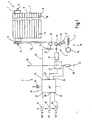
- the arrangement has a roller shutter 1, which can be set via a drive device 2 optionally in motion.
- the control of the drive device 2 takes place with the aid of a control device 3.
- To the shutter 1 includes a winding shaft 4, which is rotatably mounted at both ends via pins 5 and 6 in a non-illustrated shutter box.
- a roller shutter curtain 7 is fixed with one edge, which consists of a plurality of mutually parallel roller shutter slats 8, which are coupled together via a tongue-and-groove connection. Its lower edge is formed by a closing strip 9, are fixed to the two stops 11 rigid.
- the stops 11 in the form of cylindrical pins can rest against the edge of the slot of the roller shutter box, not shown, in order to prevent the roller shutter curtain 7 disappears completely in the roller shutter box. They work so far together with the slot of the roller shutter box as a mechanical end stop.
- a belt pulley 12 is arranged, which is rotatably connected to the winding shaft 4.
- a tension belt 13 can be wound, which is fixed with one end on the belt pulley 12.
- the belt pulley 12 is, as usual in roll shops, a flanged wheel to prevent a lateral run down of the tension belt 13.
- the tension belt 13 is symbolically illustrated in its lower end in Fig. 1 in the form of a dashed line.
- the drive device 2 which interacts with the tension belt 13 at the lower end, is shown in a highly schematized manner and also rotated by 90 ° in order to be able to illustrate the course of the tension belt 13.
- To the drive means 2 include a first friction roller 14 which is driven via a permanent-magnet DC motor 15 with reduction gear, two further friction rollers 16 and 17 which are non-rotatably connected via not shown spur gears with the friction roller 14 and axially parallel to this, as well as in the Wall of the relevant building accommodated automatic winding 18 with a belt pulley 19 which is biased by a symbolically indicated spring 21 in the winding direction of the tension belt 13.
- the lower end of the tension belt 13 is mounted on the disc 19, so that by means of the spring 21, which acts as a spring motor, the portion of the tension belt 13 between the friction roller 17 and the take-up disc 19 is kept taut.
- the motor 15 and the friction rollers 14, 16 and 17 are arranged and stored together in a non-illustrated board.
- a sensing roller 22 is also rotatably mounted, namely about an axis which is parallel to the axes of the friction rollers 14, 16 and 17 and the take-up disc 19.
- the sensing roller 22 is arranged so that the tensioned tension belt 13 runs over the peripheral surface and the follower roller 22 can take by friction.
- a disc 23 is rotatably coupled, which is scanned by a sensor 24.
- the sensor 24 may be an optical or a magnetic field sensor which senses irregularities on the disk 23 and emits an electrical pulse via a connecting line 25 at each pass of nonuniformity.
- the number of pulses delivered is proportional to the distance traveled by the tension belt 13.
- the core of the control device 3 forms a microcontroller or microprocessor 26, which has a plurality of inputs 27, 28, 29, 31 and 32 and a control output 33.
- a microcontroller or microprocessor 26 which has a plurality of inputs 27, 28, 29, 31 and 32 and a control output 33.
- the microcontroller 26 it is also possible to use an ASIC which is configured or wired according to the program explained below.
- the line 25 is connected, via which the microcontroller 26 pulses are supplied as long as the sensing roller 22 rotates, which is equivalent to a movement of the tension belt 13.
- the pulses are continuously counted by means of a counter and deliver so information about the position of the shutter curtain 7.
- the counter is a forward / backward counter, which also takes into account the sign. For example, it counts forward when the shutter curtain 7 moves up, and backwards when the shutter curtain moves down.
- the maximum count starting from 0 is greater than the maximum in both directions expected number of pulses when the shutter curtain 7 passes through its full stroke. In this way, there is no overflow when the counter is reset when the shutter curtain 7 is in one of its physically possible limit positions.
- buttons 34, 35 and 36 are connected via corresponding lines, whose other contact, as the upward arrow shows, is connected to the positive supply voltage.
- the two push-buttons 34 and 35 serve as directional buttons, while the push-button 36 is a set or programming switch.
- the output 33 is connected to a symbolically indicated relay switch group 37, via which the electrical connection from a supply voltage 38 to the motor 15 and from the motor 15 via a current sensor resistor 39 to the circuit ground 41 can be produced.
- the relay switch group 37 also serves as Umpolschalter for the motor 15, whereby a total of three states are at least possible, namely a switch-off, in which the motor 15 gets no power and is short-circuited at the input, and two switch-on, in which he with the one or other polarity between the power supply 38 and the circuit ground 41 is located. It is understood that the output 33 may be a multi-pole output to allow for these multiple switching states of the relay switch group 37.
- the input 31 is finally connected to the hot end of the current sensing resistor 39 to measure the voltage drop across the current sensing resistor 39.
- the voltage drop serves as a criterion for the physical limit of the shutter curtain 7.
- the microcontroller contains a Spannugsdiskriminator that compares the voltage drop with an internally predetermined threshold and depending on the comparison provides a corresponding binary signal.
- the discriminator may also be implemented outside the microcontroller.
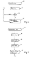
- the microprocessor 26 Upon power up, the microprocessor 26 is started at the designated start address and initially unwraps a program at 51 which normalizes the registers and sets certain memory variables to an initial value required for the run. This includes the presetting of the internal counter, which counts the pulses at the input 32. The counter is e.g. set to zero.
- the program proceeds and queries 52 whether the running direction key 34, with which the opening of the shutter 1 is arranged, is actuated. If so, the program immediately returns to the beginning of the query block 52. This is to prevent accidentally immediately after switching on the power supply or a voltage return of the roller shutter 1 is set in motion in one direction. If the direction key 34 is not actuated, the program enters a second query block 53, in which the program checks whether the other direction key 35, with the closing the shutter 1 is requested, is pressed. If so, the program goes to the beginning of the query block 53 and only in the event that no key is pressed does the program proceed to a next instruction block 54.
- the query block 53 has the same function as the query block 52, namely to prevent erroneous or unwanted startup of the shutter 1.
- the instruction block 54 is executed, in which a plurality of variables, a variable MSA, a variable MSE, a variable MP is reset, and a short-time counter (stopwatch) SZ is loaded.
- a display 55 optionally connected to the microprocessor can be switched off at this point. This light-emitting diode 55 signals to the user that the control device 3 is programmable in the sense of establishing a user-defined end position.
- the variables MSA and MSE are used to detect their release after an actuation of the settable 36 and to start the "stopwatch" only from this point in time. In this respect, the variables serve to realize a negative edge triggering, as is clear from the following description.
- a query block 56 is executed, in which the program checks whether the direction key 34 is actuated. If so, a subroutine 57 is started which causes the shutter 1 to open. If the key 34 is not actuated, the program continues with a query block 59, in which the key 35 is checked. If it is pressed, the user wishes to close the shutter 1, which is why Program at 58 changes to the corresponding subroutine. If there is no action, the query block 59 is followed by a query block 61, in which it is checked whether the variable MSE is set. If not, the program checks at 62 whether the user holds the settest key 36 pressed. If this is not the case, then the program returns to the input of the query block 56.
- an instruction block 63 is executed.
- the variables MSE and MP are set and, in addition, the light emitting diode 55 is turned on. Thereafter, the program returns to the input of the query block 56.
- variable MSE is actually set, thus branching the program at the query block 61 to the input of a query block 64, in which it is checked whether the variable MSA is additionally set. If so, the check is made in a query block 65 as to whether the settest key 36 is in the actuated state. If not, this is a sign that the user has released the settest key 36, whereby the stopwatch formed by the variable SZ starts to run, so that the programming of an end position is possible only for a predetermined time, to preclude erroneous operations. This time is realized by the running time of the stopwatch defined by the variables SZ, which is thus decremented in an instruction block 66, and indicated by the light emitting diode 55.
- variable SZ has not yet returned to zero, which is checked in a query block 67, the program returns to the beginning of the query block 56. If, on the other hand, the variable SZ decrements to zero has been, the "stopwatch" has expired and it is no longer possible to program the end position by the directional keys 34, 35 until the settable key 36 is pressed again. The running direction keys 34, 35 are then only used to set the roller shutter 1 up or down in motion, which corresponds to the normal operation. The program therefore returns to the input of the instruction block 52 in the event that SZ has become zero. The set time has expired and must be restarted if necessary.
- the further query is made as to whether the settable 36 is still in the actuated state. This check is done in a query block 68. If the user has released the settest key 36, i. it is in the state with open switch, then in the instruction block 69, the variable MSA is set before the program returns to the input of the query block 56 at the output of the instruction block 69.
- the instruction block 69 is skipped.
- a programming of arbitrarily defined end positions described below is only possible from the time after the user has released the settest key 36.
- a time begins to run within which he must have started the procedure for programming the end position by having either the run direction key 34 for setting an upper end position or the running direction key 35 for defining a lower arbitrary end position actuated. After the expiry of this Time is a change or adjustment of the gewillkürten end positions is no longer possible until re-pressing the settable 36.
- the running direction keys 34, 35 serve as already mentioned then only to set the shutter 1 up or down in motion, which corresponds to the normal operation ,
- This program section first checks whether the current position corresponds to the upper end position. This is done by comparing the counter content of the above-mentioned pulse counter with a stored value corresponding to the counter content at the respective end position; these are the variables "upper limit” or "maximum limit position above” which are explained below.
- This counter receives its count pulses via the input 32 from the pulse generator, which is formed by the encoder 23 and the sensor 24. This pulse generator provides pulses as long as the tension belt 13 moves, wherein the number of pulses of the distance is proportional to the traction belt 13 travels.
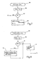
- the check takes place in a query block 71. If the upper limit position has already been reached, the subroutine is immediately exited, namely to the input of the request block 52. If the upper end position has not yet been reached, an instruction block 73 ensures that signals are output via the output 33 to the relay switch set 37 so that the motor 15 for the corresponding direction of rotation is connected to the supply voltage 38. Subsequently, in a statement block 74, a waiting loop is started before the program continues from there to a query block 75.
- the inquiry block 75 it is checked whether the current through the sensor resistor 39, i. the voltage drop across the sensor resistor 39 is above or below a predetermined threshold.
- the exceeding of the limit value arises when the torque requested by the motor exceeds a corresponding limit value. This is usually the case when the stops 11 come to rest on the slot of the roller shutter box, which in turn is equivalent to the maximum possible upper limit position of the roller shutter 1.
- the current sensor resistor 39 together with the discriminator implemented in the microcontroller 26, serves as a detection device for the upper physically possible limit position.
- the check in the query block 75 is not made immediately following the instruction block 73, but delayed by the instruction block 74.
- the variable MAUF serves as a flip-flop and is intended to ensure that the roller shutter 1 continues to open in the sense of opening, even if the user has already released the relevant directional-direction button 34.
- the variable MAUF is set after releasing the running direction key 34 and reset by a renewed actuation. Accordingly, on the first pass through the program part of FIG. 3, the variable MAUF is not set and the program proceeds to the query block 77 with another query block 78, in which the state of the running direction key 34 is checked. If it is no longer in the actuated state, the variable MAUF is set after the query block 78 in the instruction block 79, otherwise the instruction block 79 is skipped.
- a query block 81 it is examined in a query block 81, whether the current position is greater than a previously defined upper position. If not, the program continues with the query block 75, otherwise the program changes to a subroutine 81 "shut down above".
- the variable MAUF will initially remain reset during the first passes, why the run is done as described above.
- the user will release the run direction key 34 so that at query block 78 the condition is satisfied and the variable MAUF is set in the instruction block 79.
- the program will continue in the future via a query block 83, in which it is checked whether the directional key 34 is pressed again in the meantime. If not, the program changes to the input of the query block 81, if so, this is understood as a command to stop the movement of the shutter curtain. Accordingly, the program proceeds via an instruction block 84 in which the variable MAUF is reset for the next run. After execution of the instruction block 84, the program enters the subroutine "shutdown above".
- the first function which is performed in program part 82 "switch-off above", takes place in a statement block 85, by which a signal is generated at the output 33, so that the relay switch block 37 interrupts the power supply to the motor 15. Subsequently, it is checked in a query block 86 whether the variable MP is set.
- This variable MP has optionally been set in the instruction block 63 ( Figure 2) when the user pressed the settest key 36.
- the user of the control device 3 With the pressing of the set button 36, the user of the control device 3 indicates his desire that the upper end position reached by the preceding operation of the running direction button 34 is set as the future arbitrary upper one End position is used, which from now on when opening the shutter curtain 7 is no longer run over. Thus, if the variable MP is set, the program changes to an instruction block 87.
- the "upper limit" variable is set to the count contents of the counter and also the variable MP is cleared. Thereafter, the program returns to the beginning of the instruction block 52 and waits for the next instruction input by operating one of the keys 34 to 36. During the waiting operation, the main branch is continuously passed through the inquiry blocks 56, 59 and 62.
- the program In the event that the variable MP was not set, the program also returns to the input of the instruction block 52 after the inquiry block 86 and waits as mentioned above. If the variable MP is not set, the instruction block 87 is not executed.
- variable "maximum end position above” is occupied in a statement block 92 with the current count.
- This variable "maximum end position above” will in the future, as already mentioned, evaluated in the query block 81, so that henceforth until the next deletion of all variables, for example due to power failure, the program piece 76 "Endabbrizzi" is no longer reached.
- the program does not require an absolute upper limit, but the controller 3 searches for the upper limit position itself, the counter contents, although the position reflects, but is not fixed to a specific position of the shutter curtain 7 at the beginning of the program run.
- the system works as it were with a "floating zero point" and looks for the upper end position itself. This upper end position is then equated with a counter content which results randomly from the initial conditions, but then remains the same until the system due to a power failure has lost his memory.
- Fig. 6 shows the program piece 58 "Close shutter". It starts by checking in a query block 93 whether the content of the counter has become smaller than the content of a variable "lower limit”. This variable corresponds mutatis mutandis to the variable "upper limit", only with the difference that this is the gewillüritzte lower limit. The manner in which this variable is obtained will be explained below.
- the program When the arbitrary lower limit position is reached, the program immediately returns to the input of the instruction block 52. Otherwise, the motor is turned on in an instruction block 94 in the sense of discharging the shutter curtain 7 via the output 33.
- the physically possible lower limit position is detected by the absence of pulses of the sensing roller 22.
- a short-time clock with the help of a retriggerable monoflop is simulated, which is reset each time a signal from the sensor 24 arrives. If these pulses remain off, the monoflop is no longer reset and thus recognized that the shutter curtain 7 is completely drained or otherwise stands up below with its lower edge.
- a variable "clock” is loaded, which is decremented in each loop pass described below. Since the time needed for looping is known, is a certain Time expired when the variable "clock" is counted down to zero. In addition, in the instruction block 95, the current count is buffered.
- variable MAB for differentiation and is not set when entering the program section. It is checked in a query block 96 which follows the instruction block 95. Because the variable MAB is not set, after query block 96, query block 97 is executed, in which key 35 is queried. If it is no longer actuated in the meantime, MAB is set in an instruction block 98 or, if the user continues to press the key 35, the instruction block 98 is skipped.
- a query block 101 If the bottom limit is not reached, in a query block 101 the variable "clock" is decremented and checked to see if it has returned to zero. If not, the program returns to the input of query block 96. Otherwise, ie when the clock has expired, it is examined in a query block 102 whether the counter contents is different from the counter content that was cached in the instruction block 95. In case of a difference between these two values, impulses from the touch roller 22 are still coming. If, on the other hand, the contents are the same, the follower roller 22 has now stopped because the tension belt 13 has lifted off the follower roller 22. The roller shutter curtain 7 is therefore on, so with a program part 103 "Endabscrien down" continues. If, on the other hand, pulses have still arrived, the lowering movement can be continued, which is why the program returns to the beginning of the instruction block 95 with further pulses arriving after the query block 102, in which the clock is reset and the count is buffered again.
- variable MAB will be set, with the result that after query block 95 the query block 96 is no longer continued, but instead branched to a query block 104.
- query block 104 the state of the running direction key 35 is checked. If it is pressed again, the shutter curtain 7 must be stopped. On the other hand, if the key 35 is not actuated, the run of the shutter curtain 7 is continued and the program changes to the input of the inquiry block 99. Otherwise, i. when the running direction key 35 is actuated, the variable MAB is reset in an instruction block 105 and the program is left in the direction of the program part 100 "switch-off below".
- the program part 100 "shutdown below" begins with the motor being switched off in a subsequent instruction block 106. Subsequently, it is checked in an instruction block 107 whether the user wanted to program an arbitrarily lower limit position, which then checks the program on the basis of the state of the variable MP, as already mentioned above. If the variable MP is not set, the program immediately returns to the input of the instruction block 52. Otherwise, in an instruction block 108, a variable "lower limit" is filled with the value of the current counter content and the variable MP is cleared.
- the loss of impulses arises because the tension belt 13 lifts from the sensing roller 22 but still runs a bit before the system detects the stoppage of the sensing roller 22.
- the correction value for this is determined empirically and ensures that when opening the shutter 1 the same upper physical position of the shutter curtain 7 is reached when the content of the counter has become equal to the variables "maximum end position above” or in the case of a user-defined end position equal to Variables "upper limit".
- This correction and storage is done in the instruction block 110, and then in an instruction block 111, the counter is set to the value corresponding to the "minimum limit down" variable before returning to the beginning of the instruction block 52.
- variable "minimum end position down” can be set to the current count and the motor 15 is moved in the upward direction until the first pulse arrives. This can be determined in the same way as has already been explained in connection with the query block 101. Then the variable "minimum end position lower” is set to the value of the current meter reading.
- variable MPU is set. If it is not set, this is a sign for the first emergence of the shutter blind 7 on a lower obstacle and it is, as described above, the count read, corrected and stored away under the variable "minimum end position down". In addition, in the instruction block 110, the variable MPU is set.
- variable MPU is set, for which reason the program branches directly into the instruction block 111.
- the counter reading is corrected by setting the internal counter to the value which the variable "minimum end position lower" has.
- roller shutter control 3 From the user's point of view, the operation of the roller shutter control 3 according to the invention is as follows:
- the roller shutter curtain 7 can be set in motion only by active intervention of the user, for example in the sense of opening, if at the time of voltage recovery of the shutter curtain 7 was closed.
- the user actuates the running direction key 34 for this purpose "OPEN" and the shutter curtain 7 will move upwards until the stops 11 come to rest on the shutter box.
- the controller carries out a corresponding correction so that the mechanical stop will no longer be reached in the future.
- the user wants to close the shutter 1, which is instructed by pressing the running direction key 35 "DOWN”.
- the roller shutter 1 will move downwards until it rises with its lower edge on any attacks and the tension belt 13 relaxes.
- the roller blind curtain 7 moves into the previously determined upper end position in which the stops 11 are just not yet abut the roller shutter box.
- the user can arbitrarily arbitrarily interim end positions program by first pressing the settable 36 and then within the available time window, which is indicated by the illumination of the light emitting diode 55, the shutter 1 on the Move direction key 34 or 35 either up or down and stop again by pressing the same key again.
- This then reached position is the end position, the future will take the shutter curtain 7, when either the directional button "OPEN” or the directional button “DOWN” is pressed without the user before by pressing the same button stops the movement.
- boundary layers can be arbitrarily defined independently of the physical boundaries. This will prevent the user from being in the shutter curtain 7 usually included light and ventilation slots over the entire length of the shutter curtain 7 are completely closed. On the other hand, he can choose an intermediate position, for example, to get a certain amount of sun protection in summer.
- variable MP is set, which corresponds to a new setting of the limit.
- the program may be designed so that when the variable MP is set by operating the settest key 36, the value of the "upper limit" variable is ignored.
- the roller shutter curtain 7 can not automatically start moving by itself. In any case, an action of the user is required, which then also easily check the movements and possibly stop the shutter curtain 7 in time before it comes to any damage.
- each of the keys can be exploited to stop the driving movement.
- further query blocks are inserted in Fig. 3 after the query block 83, in which additionally the other directional key 35 and the settable 36 are queried for actuation.
- a roller shutter assembly include a operated via a tension belt blinds curtain and an electric drive device for the tension belt and a controller for the drive motor.
- the controller monitors the motor current to detect the upper physically possible limit position of the shutter curtain, and there is also a follower roller which is frictionally taken along by the tension belt and provides pulses to the controller.
- the motor shuts off when either the motor current exceeds a predetermined limit or the sensing roller stops delivering pulses.
- the controller operates to determine a position with a counter and is designed so that the counter, depending on a random initial value, operates when starting the arrangement.
Landscapes
- Engineering & Computer Science (AREA)
- Structural Engineering (AREA)
- Architecture (AREA)
- Civil Engineering (AREA)
- Operating, Guiding And Securing Of Roll- Type Closing Members (AREA)
- Extrusion Moulding Of Plastics Or The Like (AREA)
- Electroplating Methods And Accessories (AREA)
- Vending Machines For Individual Products (AREA)
- Non-Portable Lighting Devices Or Systems Thereof (AREA)
- Shutters For Cameras (AREA)
Claims (16)
- Dispositif de commande d'un volet roulant comprenant un rideau de volet roulant (7) qui peut être enroulé sur un arbre de volet roulant (4), le rideau de volet roulant présentant une position physique de fin de course supérieure et une position physique de fin de course inférieure et dont l'arbre de volet roulant (4) est entraîne par l'intermédiaire d'une courroie de volet roulant (13) au moyen d'un moteur électrique (15) qui agit sur ladite courroie de volet roulant (13) et qui est commandé par un dispositif de commande (3), le dispositif de commande (3) comprenant au moins:- un dispositif de mémorisation dans lequel est enregistrée une valeur numérique correspondant à la position de fin de course supérieure du rideau de volet roulant,- un processeur (26) qui sert à détecter, par l'intermédiaire d'un compteur/décompteur, la course du rideau de volet roulant (7),- un dispositif de surveillance (23, 24, 39) du rideau de volet roulant (13), qui est raccordé au processeur (26) et qui sert à déterminer si le rideau de volant roulant (7) a atteint sa position physique maximale possible de fin de course supérieur ou inférieure,- un dispositif d'entrée (34, 35, 36) qui comprend au moins deux touches directionnelles (34, 36) pour commander le sens de déplacement du volet roulant (1), le programme et/ou le câblage du dispositif étant conçu de manière que :- en actionnant la touche directionnelle (34, 35) correspondant à la fermeture du rideau de volet roulant, le moteur électrique (15) est mis en route dans le sens de fermeture du rideau de volet roulant,- en mettant le moteur électrique (15) à l'arrêt dès que le dispositif de surveillance (23, 24, 39) établit que la position physique maximale possible de fin de course inférieure est atteinte et- en corrigeant aussitôt la valeur contenue dans le compteur/decompteur.
- Dispositif selon la revendication 1, caractérisé en ce que, pour effectuer la correction, tla valeur contenue dans le compteur/decompteur est modifiée par addition ou par soustraction de la valeur de correction.
- Dispositif selon la revendication 1, caractérisé en ce que dans le dispositif de mémorisation est enregistrée une valeur de référence qui représente la course de retour pour atteindre la position de fin de course inférieure lors de la fermeture et qui est détectée seulement une fois dans un parcours d'initialisation.
- Dispositif selon la revendication 1, caractérisé en ce que le compteur/décompteur est placé sur la valeur de référence quand la position inférieure maximale physiquement possible est atteinte.
- Dispositif selon la revendication 1, caractérisé en ce que l'utilisateur peut définir et introduire dans le dispositif de commande (3) une position supérieure de fin de course pour le rideau de volet roulant (7), cette position se trouvant entre la position limite physique supérieure et la position limite physique inférieure.
- Dispositif selon la revendication 1, caractérisé en ce que l'utilisateur peut définir et introduire dans le dispositif de commande (3) une position inférieure de fin de course pour le rideau de volet roulant (7), cette position se trouvant entre la position physique limite supérieure et la position physique limite inférieure.
- Dispositif selon la revendication 6, avec au moins une touche de positionnement (36) pour commander une fonction de mémorisation, caractérisé en ce que pour introduire une position de fin de course supérieure définie par l'utilisateur, le rideau de volet roulant (7) est d'abord amené dans une position qui se trouve en dessous de celle-ci, puis la touche de positionnement (36) est enfoncée, et ensuite la touche directionnelle (34) servant à mettre en mouvement ascendant le rideau de volet roulant (7) est enfoncée, et quand la position de fin de course supérieure définie par l'utilisateur est atteinte, soit la même touche (34) soit l'autre touche directionnelle (35) ou la touche de positionnement (36) est enfoncée et ainsi, dans le dispositif de mémorisation, est enregistré un état qui correspond à la position de fin de course supérieure définie par l'utilisateur.
- Dispositif selon la revendication 6, avec au moins une touche de positionnement (36) pour commander une fonction de mémorisation, caractérisé en ce que pour introduire une position de fin de course inférieure définie par l'utilisateur, le rideau de volet roulant (7) est d'abord amené dans une position qui se trouve au-dessus de celle-ci, puis la touche de positionnement (36) est enfoncée, et ensuite la touche directionnelle (34) servant à mettre en mouvement descendant le rideau de volet roulant (7) est enfoncée, et quand la position de fin de course supérieure définie par l'utilisateur est atteinte, soit la même touche (34) soit l'autre touche directionnelle (35) ou la touche de positionnement (36) est enfoncée et ainsi, dans le dispositif de mémorisation, est enregistré un état qui correspond à la position de fin de course inférieure définie par l'utilisateur.
- Dispositif selon la revendication 1, caractérisé en ce que le dispositif de surveillance (24, 25, 39) comprend un générateur d'impulsions (23, 24).
- Dispositif selon la revendication 9, caractérisé en ce que- l'état mis en mémoire pour la position de fin de course supérieure définie par l'utilisateur correspond à un état prédéfini du compteur, de préférence l'état "zéro",- quand le rideau de volet roulant (7) se ferme, le compteur compte dans un sens, tandis que quand le rideau de volet roulant (7) s'ouvre, il compte dans l'autre sens, jusqu'à ce que l'état de compteur correspondant à la position de fin de course supérieure définie par l'utilisateur soit atteint à nouveau, et dans cette position le moteur électrique (15) est coupé par le dispositif de commande (3).
- Dispositif selon la revendication 8, caractérisé en ce que la position physique limite inférieure correspond à un état du compteur qui, en partant de la position de fin de course supérieure définie par l'utilisateur ou de la position physique limite supérieure, est atteint quand le rideau de volet roulant (7) se ferme.
- Dispositif selon la revendication 1, caractérisé en ce que le mouvement du rideau de volet roulant (7) est stoppé quand- soit la position limite supérieure physiquement possible du rideau de volet roulant (7) est atteinte,- soit est atteinte une position supérieure de fin de course qui est plus basse que la position limite supérieure physiquement possible,- soit la position limite inférieure physiquement possible du rideau de volet roulant (7) est atteinte,- soit est atteinte une position supérieure de fin de course définie par l'utilisateur ou une position inférieure de fin de course définie par l'utilisateur,- soit la touche directionnelle (34, 35) déclenchant le mouvement est à nouveau enfoncée,- soit est enfoncée l'autre touche directionnelle (34, 35) qui n'avait pas déclenché le mouvement
- Dispositif selon la revendication 1, caractérisé en ce que pour saisir la position limite supérieure possible physiquement, le dispositif de surveillance (39) présente un dispositif de surveillance de l'intensité du moteur qui compare celle-ci à une valeur limite.
- Dispositif selon la revendication 13, caractérisé en ce que la comparaison a lieu seulement après que le courant alimentant le moteur ait été enclenché pendant un temps prédéfini.
- Dispositif selon la revendication 10 ou 11, caractérisé en ce que l'état correspondant à la position supérieure de fin de course correspond à un état du compteur.
- Dispositif selon la revendication 16, caractérisé en ce que le rideau de volet roulant (7), après avoir atteint la position supérieure de fin de course physiquement possible est déplacée d'une quantité prédéfinie dans le sens de fermeture et, dans cette position du rideau (7), un état correspondant est mémorisé en tant que position de fin de course supérieure.
Priority Applications (3)
| Application Number | Priority Date | Filing Date | Title |
|---|---|---|---|
| EP03016932A EP1359285A1 (fr) | 1998-03-06 | 1999-03-05 | Dispostif de commande d'un volet roulant |
| EP03016933A EP1359286A1 (fr) | 1998-03-06 | 1999-03-05 | Dispositif de commande pour un volet à rouleau |
| EP03016021A EP1359284B1 (fr) | 1998-03-06 | 1999-03-05 | Dispositif de commande d'un volet roulant |
Applications Claiming Priority (2)
| Application Number | Priority Date | Filing Date | Title |
|---|---|---|---|
| DE1998109594 DE19809594B4 (de) | 1998-03-06 | 1998-03-06 | Rollladensteuerung |
| DE19809594 | 1998-03-06 |
Related Child Applications (6)
| Application Number | Title | Priority Date | Filing Date |
|---|---|---|---|
| EP03016932A Division EP1359285A1 (fr) | 1998-03-06 | 1999-03-05 | Dispostif de commande d'un volet roulant |
| EP03016021A Division EP1359284B1 (fr) | 1998-03-06 | 1999-03-05 | Dispositif de commande d'un volet roulant |
| EP03016933A Division EP1359286A1 (fr) | 1998-03-06 | 1999-03-05 | Dispositif de commande pour un volet à rouleau |
| EP03016021.2 Division-Into | 2003-07-15 | ||
| EP03016932.0 Division-Into | 2003-07-25 | ||
| EP03016933.8 Division-Into | 2003-07-25 |
Publications (2)
| Publication Number | Publication Date |
|---|---|
| EP0940554A1 EP0940554A1 (fr) | 1999-09-08 |
| EP0940554B1 true EP0940554B1 (fr) | 2006-10-04 |
Family
ID=7859920
Family Applications (1)
| Application Number | Title | Priority Date | Filing Date |
|---|---|---|---|
| EP99104415A Expired - Lifetime EP0940554B1 (fr) | 1998-03-06 | 1999-03-05 | Dispositif de commande pour un volet à rouleau |
Country Status (4)
| Country | Link |
|---|---|
| EP (1) | EP0940554B1 (fr) |
| AT (2) | ATE341693T1 (fr) |
| DE (3) | DE19861119B4 (fr) |
| ES (2) | ES2270545T3 (fr) |
Families Citing this family (7)
| Publication number | Priority date | Publication date | Assignee | Title |
|---|---|---|---|---|
| FR2803622B1 (fr) * | 2000-01-11 | 2002-03-22 | Jouvence | Procede de controle du deplacement d'un element de fermeture qui s'enroule autour d'un tambour motorise et moyens pour la mise en oeuvre du procede |
| DE10209292C1 (de) * | 2002-03-01 | 2003-11-13 | Stehle & Soehne Ag J | Verfahren zur Einstellung zumindest einer flexiblen Endposition bei einer Jalousie |
| DE10232885B3 (de) * | 2002-07-19 | 2004-02-19 | Hans Arnhold | Rollladen mit Einbruchswarneinrichtung |
| CN101638974B (zh) * | 2008-07-28 | 2011-07-20 | 陈耀华 | 电动卷帘驱动控制器的卷帘位置检测方法及传感装置 |
| DE202010015105U1 (de) * | 2010-11-08 | 2012-02-09 | Arca Beteiligungen Gmbh | Antrieb für eine Verdunkelungsvorrichtung |
| DK179835B1 (en) | 2017-11-10 | 2019-07-26 | Vkr Holding A/S | A method for determining a fully extended position of a screening body of a screening device |
| DK201770846A1 (en) | 2017-11-10 | 2019-05-21 | Vkr Holding A/S | Screening arrangement with improved mounting bracket and end piece, window with such a mounting bracket and method of installing and uninstalling a screening arrangement in the window |
Citations (1)
| Publication number | Priority date | Publication date | Assignee | Title |
|---|---|---|---|---|
| EP0744524A2 (fr) * | 1995-05-24 | 1996-11-27 | Robert Bosch Gmbh | Dispositif pour la commande électronique de mouvements d'un volet à rouleau |
Family Cites Families (10)
| Publication number | Priority date | Publication date | Assignee | Title |
|---|---|---|---|---|
| DE1274323B (de) * | 1964-12-10 | 1968-08-01 | Hans Wiegelmann Dipl Volksw | Elektromotorischer Antrieb fuer die Aufwickelrolle eines Zugorganes eines Rolladens od. dgl. |
| DE3214235C2 (de) * | 1982-04-17 | 1989-06-08 | Willi 4292 Rhede Rademacher | Gurtkasten für eine Verdunkelungsvorrichtung |
| DE3241123A1 (de) * | 1982-11-06 | 1984-05-10 | Richard 5030 Hürth Greis | Elektrischer aufzug fuer rollaeden und jalousien an fenstern |
| EP0273719B2 (fr) * | 1986-12-29 | 1995-07-26 | Sharp Kabushiki Kaisha | Store manoeuvrable électriquement |
| SE500651C2 (sv) * | 1989-01-20 | 1994-08-01 | Ambient Energy Design | Anordning för reglering av drivmotorn hos fönsterjalusier eller markiser |
| DE3933266A1 (de) * | 1989-10-05 | 1991-01-31 | Baumann Rolladen | Verfahren zur steuerung eines elektromotors fuer einen rolladen, insbesondere faltrolladen und steuereinheit hierfuer |
| JP3268376B2 (ja) * | 1993-09-02 | 2002-03-25 | 三和シヤッター工業株式会社 | 建築用電動シャッターにおける補正装置 |
| DE19523914C1 (de) * | 1995-06-30 | 1996-09-05 | Bosch Gmbh Robert | Vorrichtung zur Erfassung der Bewegung eines Antriebsgurts für einen Rolladenpanzer |
| FR2743602B1 (fr) * | 1996-01-12 | 1998-10-09 | Somfy | Installation de fermeture ou de protection solaire motorisee |
| DE19630491C1 (de) * | 1996-07-29 | 1998-02-05 | Selve Ernst Gmbh Co Kg | Schaltungsanordnung zur Steuerung von elektromotorischen Antrieben für auf- und abwickelbare Behänge |
-
1998
- 1998-03-06 DE DE19861119A patent/DE19861119B4/de not_active Expired - Fee Related
-
1999
- 1999-03-05 AT AT99104415T patent/ATE341693T1/de not_active IP Right Cessation
- 1999-03-05 DE DE59913919T patent/DE59913919D1/de not_active Expired - Lifetime
- 1999-03-05 ES ES99104415T patent/ES2270545T3/es not_active Expired - Lifetime
- 1999-03-05 EP EP99104415A patent/EP0940554B1/fr not_active Expired - Lifetime
- 1999-03-05 DE DE59913886T patent/DE59913886D1/de not_active Expired - Lifetime
- 1999-03-05 AT AT03016021T patent/ATE342425T1/de not_active IP Right Cessation
- 1999-03-05 ES ES03016021T patent/ES2269875T3/es not_active Expired - Lifetime
Patent Citations (1)
| Publication number | Priority date | Publication date | Assignee | Title |
|---|---|---|---|---|
| EP0744524A2 (fr) * | 1995-05-24 | 1996-11-27 | Robert Bosch Gmbh | Dispositif pour la commande électronique de mouvements d'un volet à rouleau |
Also Published As
| Publication number | Publication date |
|---|---|
| ATE341693T1 (de) | 2006-10-15 |
| DE19861119A1 (de) | 2000-03-02 |
| DE19861119B4 (de) | 2004-05-27 |
| EP0940554A1 (fr) | 1999-09-08 |
| ES2269875T3 (es) | 2007-04-01 |
| ATE342425T1 (de) | 2006-11-15 |
| DE59913886D1 (de) | 2006-11-16 |
| DE59913919D1 (de) | 2006-11-23 |
| ES2270545T3 (es) | 2007-04-01 |
Similar Documents
| Publication | Publication Date | Title |
|---|---|---|
| EP0770757B2 (fr) | Méthode pour actionner des vélums ou des choses pareilles par moteur électrique | |
| DE69412489T3 (de) | In der kopfschiene montierte betätigungsvorrichtung für einen rolladen mit mini-lamellen | |
| DE69716302T2 (de) | Motorisiertes fensterblendschutz system | |
| EP0716214B2 (fr) | Procédé et dispositif pour contrôler l'arrêt d'un volet roulant ou similaire entraîné par un moteur électrique | |
| DE2902683A1 (de) | Steuerschaltung fuer fahrzeugfenster- betaetigungsvorrichtungen | |
| EP0703344B1 (fr) | Dispositif d'arrêt automatique d'un store à rouleau, notamment un volet roulant | |
| DE3538797C2 (fr) | ||
| DE102004007883A1 (de) | Automatischer Torantrieb | |
| CH678749A5 (fr) | ||
| DE19861119B4 (de) | Rollladensteuerung | |
| EP0744524B1 (fr) | Dispositif pour la commande électronique de mouvements d'un volet à rouleau | |
| EP1359284B1 (fr) | Dispositif de commande d'un volet roulant | |
| DE19809594B4 (de) | Rollladensteuerung | |
| DE19605273C2 (de) | Rollo mit einem auf eine Wickelwelle auf- und von dieser abwickelbaren Wickelmedium | |
| EP2634358B2 (fr) | Détection d'obstacles intelligente | |
| EP1759083B1 (fr) | Commande d'enrouleur de courroie de volets roulants | |
| EP1319795B1 (fr) | Appareil d'entraînement de tubes avec système de commande dans une protection solaire ou un dispositif d'occultation | |
| DE60102961T2 (de) | Motorisierte Antriebsvorrichtung von beweglichen Einrichtungen wie Rollos od.dgl. und Methode zur Bedienung | |
| EP2186989A2 (fr) | Commande de moteur | |
| DE4442948A1 (de) | Vorrichtung zur Steuerung von beweglichen Einrichtungen wie Rolltoren o. dgl. | |
| DE60105669T2 (de) | Antriebssteuerung für eine Verschlussvorrichtung, die auf einer motorgetriebenen Welle aufrollbar ist, sowie Vorrichtung zur Durchführung dieser Steuerung | |
| EP1149451A1 (fr) | Procede et commande pour commander un dispositif d'entrainement destine a une installation de fermeture d'un batiment ou d'une enceinte | |
| DE9421948U1 (de) | Vorrichtung zur Stillstandssteuerung von elektromotorisch betriebenen Rolläden o.dgl. | |
| DE202023100870U1 (de) | Behangsystem | |
| DE10250799A1 (de) | Rollladensteuerung mit Helligkeitsanzeige |
Legal Events
| Date | Code | Title | Description |
|---|---|---|---|
| PUAI | Public reference made under article 153(3) epc to a published international application that has entered the european phase |
Free format text: ORIGINAL CODE: 0009012 |
|
| AK | Designated contracting states |
Kind code of ref document: A1 Designated state(s): AT BE CH CY DE DK ES FI FR GB GR IE IT LI LU MC NL PT SE |
|
| AX | Request for extension of the european patent |
Free format text: AL;LT;LV;MK;RO;SI |
|
| 17P | Request for examination filed |
Effective date: 20000225 |
|
| AKX | Designation fees paid |
Free format text: AT BE CH CY DE DK ES FI FR GB GR IE IT LI LU MC NL PT SE |
|
| 17Q | First examination report despatched |
Effective date: 20030129 |
|
| GRAP | Despatch of communication of intention to grant a patent |
Free format text: ORIGINAL CODE: EPIDOSNIGR1 |
|
| GRAS | Grant fee paid |
Free format text: ORIGINAL CODE: EPIDOSNIGR3 |
|
| GRAA | (expected) grant |
Free format text: ORIGINAL CODE: 0009210 |
|
| AK | Designated contracting states |
Kind code of ref document: B1 Designated state(s): AT BE CH CY DE DK ES FI FR GB GR IE IT LI LU MC NL PT SE |
|
| PG25 | Lapsed in a contracting state [announced via postgrant information from national office to epo] |
Ref country code: IT Free format text: LAPSE BECAUSE OF FAILURE TO SUBMIT A TRANSLATION OF THE DESCRIPTION OR TO PAY THE FEE WITHIN THE PRESCRIBED TIME-LIMIT;WARNING: LAPSES OF ITALIAN PATENTS WITH EFFECTIVE DATE BEFORE 2007 MAY HAVE OCCURRED AT ANY TIME BEFORE 2007. THE CORRECT EFFECTIVE DATE MAY BE DIFFERENT FROM THE ONE RECORDED. Effective date: 20061004 Ref country code: IE Free format text: LAPSE BECAUSE OF FAILURE TO SUBMIT A TRANSLATION OF THE DESCRIPTION OR TO PAY THE FEE WITHIN THE PRESCRIBED TIME-LIMIT Effective date: 20061004 Ref country code: FI Free format text: LAPSE BECAUSE OF FAILURE TO SUBMIT A TRANSLATION OF THE DESCRIPTION OR TO PAY THE FEE WITHIN THE PRESCRIBED TIME-LIMIT Effective date: 20061004 |
|
| REG | Reference to a national code |
Ref country code: GB Ref legal event code: FG4D Free format text: NOT ENGLISH |
|
| REG | Reference to a national code |
Ref country code: CH Ref legal event code: NV Representative=s name: SCHNEIDER FELDMANN AG PATENT- UND MARKENANWAELTE Ref country code: CH Ref legal event code: EP |
|
| REG | Reference to a national code |
Ref country code: IE Ref legal event code: FG4D Free format text: LANGUAGE OF EP DOCUMENT: GERMAN |
|
| REF | Corresponds to: |
Ref document number: 59913886 Country of ref document: DE Date of ref document: 20061116 Kind code of ref document: P |
|
| PG25 | Lapsed in a contracting state [announced via postgrant information from national office to epo] |
Ref country code: SE Free format text: LAPSE BECAUSE OF FAILURE TO SUBMIT A TRANSLATION OF THE DESCRIPTION OR TO PAY THE FEE WITHIN THE PRESCRIBED TIME-LIMIT Effective date: 20070104 Ref country code: DK Free format text: LAPSE BECAUSE OF FAILURE TO SUBMIT A TRANSLATION OF THE DESCRIPTION OR TO PAY THE FEE WITHIN THE PRESCRIBED TIME-LIMIT Effective date: 20070104 |
|
| GBT | Gb: translation of ep patent filed (gb section 77(6)(a)/1977) |
Effective date: 20070111 |
|
| PGFP | Annual fee paid to national office [announced via postgrant information from national office to epo] |
Ref country code: NL Payment date: 20070313 Year of fee payment: 9 |
|
| PGFP | Annual fee paid to national office [announced via postgrant information from national office to epo] |
Ref country code: CH Payment date: 20070314 Year of fee payment: 9 |
|
| PG25 | Lapsed in a contracting state [announced via postgrant information from national office to epo] |
Ref country code: PT Free format text: LAPSE BECAUSE OF FAILURE TO SUBMIT A TRANSLATION OF THE DESCRIPTION OR TO PAY THE FEE WITHIN THE PRESCRIBED TIME-LIMIT Effective date: 20070316 |
|
| PGFP | Annual fee paid to national office [announced via postgrant information from national office to epo] |
Ref country code: GB Payment date: 20070322 Year of fee payment: 9 |
|
| ET | Fr: translation filed | ||
| REG | Reference to a national code |
Ref country code: ES Ref legal event code: FG2A Ref document number: 2270545 Country of ref document: ES Kind code of ref document: T3 |
|
| REG | Reference to a national code |
Ref country code: IE Ref legal event code: FD4D |
|
| PLBE | No opposition filed within time limit |
Free format text: ORIGINAL CODE: 0009261 |
|
| STAA | Information on the status of an ep patent application or granted ep patent |
Free format text: STATUS: NO OPPOSITION FILED WITHIN TIME LIMIT |
|
| 26N | No opposition filed |
Effective date: 20070705 |
|
| BERE | Be: lapsed |
Owner name: ARNHOLD, HANS Effective date: 20070331 |
|
| PG25 | Lapsed in a contracting state [announced via postgrant information from national office to epo] |
Ref country code: BE Free format text: LAPSE BECAUSE OF NON-PAYMENT OF DUE FEES Effective date: 20070331 |
|
| PG25 | Lapsed in a contracting state [announced via postgrant information from national office to epo] |
Ref country code: MC Free format text: LAPSE BECAUSE OF NON-PAYMENT OF DUE FEES Effective date: 20070331 |
|
| PG25 | Lapsed in a contracting state [announced via postgrant information from national office to epo] |
Ref country code: GR Free format text: LAPSE BECAUSE OF FAILURE TO SUBMIT A TRANSLATION OF THE DESCRIPTION OR TO PAY THE FEE WITHIN THE PRESCRIBED TIME-LIMIT Effective date: 20070105 |
|
| PGFP | Annual fee paid to national office [announced via postgrant information from national office to epo] |
Ref country code: ES Payment date: 20080328 Year of fee payment: 10 |
|
| PGFP | Annual fee paid to national office [announced via postgrant information from national office to epo] |
Ref country code: IT Payment date: 20080326 Year of fee payment: 10 |
|
| PGFP | Annual fee paid to national office [announced via postgrant information from national office to epo] |
Ref country code: AT Payment date: 20080314 Year of fee payment: 10 |
|
| PGFP | Annual fee paid to national office [announced via postgrant information from national office to epo] |
Ref country code: FR Payment date: 20080314 Year of fee payment: 10 |
|
| REG | Reference to a national code |
Ref country code: CH Ref legal event code: PL |
|
| GBPC | Gb: european patent ceased through non-payment of renewal fee |
Effective date: 20080305 |
|
| PG25 | Lapsed in a contracting state [announced via postgrant information from national office to epo] |
Ref country code: NL Free format text: LAPSE BECAUSE OF NON-PAYMENT OF DUE FEES Effective date: 20081001 |
|
| NLV4 | Nl: lapsed or anulled due to non-payment of the annual fee |
Effective date: 20081001 |
|
| PG25 | Lapsed in a contracting state [announced via postgrant information from national office to epo] |
Ref country code: LI Free format text: LAPSE BECAUSE OF NON-PAYMENT OF DUE FEES Effective date: 20080331 Ref country code: CH Free format text: LAPSE BECAUSE OF NON-PAYMENT OF DUE FEES Effective date: 20080331 |
|
| PG25 | Lapsed in a contracting state [announced via postgrant information from national office to epo] |
Ref country code: GB Free format text: LAPSE BECAUSE OF NON-PAYMENT OF DUE FEES Effective date: 20080305 |
|
| PG25 | Lapsed in a contracting state [announced via postgrant information from national office to epo] |
Ref country code: LU Free format text: LAPSE BECAUSE OF NON-PAYMENT OF DUE FEES Effective date: 20070305 Ref country code: CY Free format text: LAPSE BECAUSE OF FAILURE TO SUBMIT A TRANSLATION OF THE DESCRIPTION OR TO PAY THE FEE WITHIN THE PRESCRIBED TIME-LIMIT Effective date: 20061004 |
|
| PG25 | Lapsed in a contracting state [announced via postgrant information from national office to epo] |
Ref country code: AT Free format text: LAPSE BECAUSE OF NON-PAYMENT OF DUE FEES Effective date: 20090305 |
|
| REG | Reference to a national code |
Ref country code: FR Ref legal event code: ST Effective date: 20091130 |
|
| PG25 | Lapsed in a contracting state [announced via postgrant information from national office to epo] |
Ref country code: FR Free format text: LAPSE BECAUSE OF NON-PAYMENT OF DUE FEES Effective date: 20091123 |
|
| REG | Reference to a national code |
Ref country code: ES Ref legal event code: FD2A Effective date: 20090306 |
|
| PG25 | Lapsed in a contracting state [announced via postgrant information from national office to epo] |
Ref country code: ES Free format text: LAPSE BECAUSE OF NON-PAYMENT OF DUE FEES Effective date: 20090306 |
|
| PG25 | Lapsed in a contracting state [announced via postgrant information from national office to epo] |
Ref country code: IT Free format text: LAPSE BECAUSE OF NON-PAYMENT OF DUE FEES Effective date: 20090305 |
|
| PGFP | Annual fee paid to national office [announced via postgrant information from national office to epo] |
Ref country code: DE Payment date: 20110331 Year of fee payment: 13 |
|
| REG | Reference to a national code |
Ref country code: DE Ref legal event code: R119 Ref document number: 59913886 Country of ref document: DE Effective date: 20121002 |
|
| PG25 | Lapsed in a contracting state [announced via postgrant information from national office to epo] |
Ref country code: DE Free format text: LAPSE BECAUSE OF NON-PAYMENT OF DUE FEES Effective date: 20121002 |