EP0940614A2 - Trassenband - Google Patents
Trassenband Download PDFInfo
- Publication number
- EP0940614A2 EP0940614A2 EP99104412A EP99104412A EP0940614A2 EP 0940614 A2 EP0940614 A2 EP 0940614A2 EP 99104412 A EP99104412 A EP 99104412A EP 99104412 A EP99104412 A EP 99104412A EP 0940614 A2 EP0940614 A2 EP 0940614A2
- Authority
- EP
- European Patent Office
- Prior art keywords
- film
- route
- strips
- strip
- belt according
- Prior art date
- Legal status (The legal status is an assumption and is not a legal conclusion. Google has not performed a legal analysis and makes no representation as to the accuracy of the status listed.)
- Withdrawn
Links
Images


Classifications
-
- H—ELECTRICITY
- H02—GENERATION; CONVERSION OR DISTRIBUTION OF ELECTRIC POWER
- H02G—INSTALLATION OF ELECTRIC CABLES OR LINES, OR OF COMBINED OPTICAL AND ELECTRIC CABLES OR LINES
- H02G9/00—Installations of electric cables or lines in or on the ground or water
- H02G9/02—Installations of electric cables or lines in or on the ground or water laid directly in or on the ground, river-bed or sea-bottom; Coverings therefor, e.g. tile
- H02G9/025—Coverings therefor, e.g. tile
-
- F—MECHANICAL ENGINEERING; LIGHTING; HEATING; WEAPONS; BLASTING
- F16—ENGINEERING ELEMENTS AND UNITS; GENERAL MEASURES FOR PRODUCING AND MAINTAINING EFFECTIVE FUNCTIONING OF MACHINES OR INSTALLATIONS; THERMAL INSULATION IN GENERAL
- F16L—PIPES; JOINTS OR FITTINGS FOR PIPES; SUPPORTS FOR PIPES, CABLES OR PROTECTIVE TUBING; MEANS FOR THERMAL INSULATION IN GENERAL
- F16L1/00—Laying or reclaiming pipes; Repairing or joining pipes on or under water
- F16L1/024—Laying or reclaiming pipes on land, e.g. above the ground
- F16L1/06—Accessories therefor, e.g. anchors
- F16L1/11—Accessories therefor, e.g. anchors for the detection or protection of pipes in the ground
Definitions
- the invention relates to a route line Preamble of claim 1.
- Such a route band is laid above ground Cables or pipelines laid in the ground, so that it is Excavation of soil by means of machines before the attack Cable / pipeline is picked up and excavated. At the routing is consistently laid by the in Soil remaining sections held and tearing. The demolished Sections should be visible.
- the route belt is made up of several layers. The two Layers are connected to one another via strip-shaped connection zones connected that between the connecting zones longitudinal pockets remain free.
- the strip-like one is formed Connection zone produced in that carrier and cover film together with a thin plastic strip arranged between them are welded as a contact agent. Thereby there is a risk of uncontrolled shrinkage.
- the route band is then in particular on the strip-shaped Connection zones warped.
- the strip-shaped connection zones are essential to the invention practically continuous in the longitudinal and transverse directions smooth, frizz-free and free of inhomogeneities and Missing parts.
- the route belt is now on the top and bottom and even in the area of the connection zones as well as in the area of the long pockets consistently smooth. This is encouraged that the top of the carrier film directly with the Bottom of the cover film along the strip-shaped connection zones connected is.
- the films of the present invention are sealed ensures the direct contact of the foils, which preferably are made of the same material for a smooth and frizz-free surface.
- the warning effect is also based on the fact that the route tape at least is particularly striking in sections.
- a throughout signal-colored material, which with a transparent Cover film is "covered” is from all sides of the Foil forth through the signal color striking.
- a route band can, for example, only from the transparent film, which will generally be the cover sheet, as well as the non-transparent, signal-colored carrier film. Then both from the side of the transparent cover film the retracted plastic strips as well as the not transparent signal-colored carrier film fully visible, so that the warning effect can develop. From the opposite The non-transparent carrier film is not covered on the side and see completely.
- the invention provides a route belt with more reliable Warning effect also because the plastic straps due to the continuously smooth and homogeneous structure of the Long pockets without tearing down with the specified length can be pulled out and there is also one of the film strips also consists of signal-colored material.
- the material of the foils and the connection is between the foils under the circumstances mentioned preferably over the life of a pipe / cable resistant.
- FIG. 1 shows a plan view of the longitudinal section of a Route belt 1. It consists of an underlying carrier film 3 and an overlying cover sheet 2.
- the cover sheet 2 is transparent and printed on the inside.
- the letters are so big that an excavator operator when the excavator bucket has picked up the line 1 immediately recognize may be what type of cable, pipe or the like below of the route band 1 is laid.
- the two film strips (cover film 2 and carrier film 3) are continuous over strip-shaped connection zones 6 over the entire length 16 of the route belt 1 immediately connected with each other.
- the striped connection zones 6 are consistently smooth, frizz-free and homogeneous.
- Of the Print text 17 is also in the area of the strip-shaped connection zones 6 visible and undistorted undistorted.
- connectionless Transverse zones form the longitudinal pockets 7.
- Several longitudinal pockets 7 are adjacent in the transverse direction 5.
- sections of colored plastic tape 8 are drawn.
- the Plastic tapes 8 have transverse lines of weakness 9.10 (crush lines, perforation lines or the like) on. In this way, sections are formed in the plastic tape 8, without cutting the tape.
- the lines of weakness 9, 10 each of adjacent sections of one of the longitudinal pockets 7 are a fixed minimum distance 11 next to the Lines of weakness 9, 10 of adjacent sections in the transverse direction 5 adjacent longitudinal pocket 7.
- the retracted plastic straps 8 are continuous Lengths.
- the plastic straps 8 of a longitudinal pocket 7 lie to the plastic straps 8 of the adjacent longitudinal pocket 7 so that the lines of weakness 9,10 from the transverse 5 adjacent plastic tapes 8 around a committed one Minimum distance 11 in the longitudinal direction 4 from each other are moved.
- all sections are preferably of the retracted plastic band 8 of the same length.
- At Can tear the route belt 1 by the blade movement optionally one of the plastic tapes 8 preprogrammed tear and the resulting end through the shovel from a the longitudinal pockets 7 of the route belt 1 are pulled out, so that the machine operator can see it. This is the minimum distance 11 is fixed.
- the Fig.2 shows a cross section through the route belt 1 1 in the direction of arrows II from FIG. 1.
- the Fig.2 is the route band in its components shown disassembled. It consists of the two superimposed Film strips 2.3.
- the top film strip is the cover film 2 and the lower film strip Carrier film 3.
- the cover film 2 consists of a transparent Material. For example, this could be non-colored polyethylene or be polyether.
- the cover sheet made of transparent Material is on its underside 14, i.e. on its inside, printed.
- the document 17 in FIG. 2 through an exaggeratedly thick, black layer shown.
- the print can also be printed on others Place the cover sheet 2, for example on the top 15, be applied.
- the two film strips 2, 3 of the pressure are applied. For the application of the pressure comes in principle on each side 12, 13, 14, 15 of the two film strips.
- the carrier film 3 or on the underside 14 of the cover film 2 offers the advantage that the print text between the foils largely from environmental influences such as moisture, chemical Attack, biological impact, etc. protected is. This will also make it last longer of the printed text 17 guaranteed.
- the material of the non-transparent film strip -im Embodiment of Figure 2 of the carrier film 3- is in the Solid color. It is preferred with a lead free one Colored masterbatch. This also makes the color especially rot-proof, because it destroys the color all the material would have to be destroyed. By the lead-free masterbatch will make the environment one such carrier film 3 guaranteed. The masterbatch is too free of other heavy metals or common, environmentally toxic Additives that can be omitted during production.
- both film strips 2, 3 consist of high density (HD) or low density (LD) polyethylene or polyether.
- HD high density
- LD low density
- cover film 2 and carrier film 3 can be made of different Materials exist.
- both foils are made of the same material.
- thermal properties of the two Film strips 2.3 identical so that during thermal treatment, for example welding, the film strips 2,3 behave compliant. This leads to a more homogeneous training the route belt for thermal or other processing.
- this is not transparent film strips - the carrier film 3- not printed. Rather, only the cover sheet 2 is on hers Bottom 14 printed what the advantages already mentioned above Has. In particular, the print is not made by glue or plastic strips covered.
- the bottom 13 of the cover film 3 and the top 15 the carrier film 2 are surfaces. Especially these surfaces 13.15 are attacking environmental factors such as chemical effects or the attack of microorganisms exposed. Therefore, these surfaces are 13, 15 generally not printed and made of durable material the film strip 2,3.
- the colored plastic tapes 8 shown between the film strips 2, 3 are - likewise in an exploded view - The colored plastic tapes 8 shown.
- the plastic band 8 has a greater thickness than the film strips 2 and 3. If the plastic band made of the same material as the film strips 2 and 3, it is therefore of great tear resistance.
- the plastic tape should not only be tear-resistant, but also also be rigid so that after picking up the Excavator shovel from the excavation / soil if possible warning to look out. It also has a rectangular shape Cross section and is smaller in the longitudinal direction 4 Extent than the foil strips 2,3.
- the increased tear resistance of the colored plastic tape 8 in connection with the section-wise laying between the film strip 2,3 ensures that when lifting a Line belt 1 by means of an excavator, the film strips 2,3 tear, while the plastic straps 8 remain intact.
- the adhesive 19 is also available at the edge of route 1.
- the adhesive 19 is preferably a polyurethane adhesive. This has an excellent Adhesion as it adheres to the moisture film of the surface responds. This is for a route belt according to the invention 1, which is buried underground, especially Advantage. A corresponding route band is required for underground burial 1 namely always a certain moisture attack exposed. The adhesive layer is then capable of this moisture attack not to solve, but rather to reinforce of liability. Furthermore, a polyurethane adhesive vapors not starting. Rather, it networks without the evaporation of for example solvents.
- the cross section of Figure 2 is as in Fig.3 shown.
- the film strips 2,3 also be welded. The welding takes place then in the same direction and also strip-shaped, as well as the gluing. To the extent that applies, what is said below also for welding. It is with the welding it should be noted that the materials of the foil strips 2, 3 are preferred have the same thermal properties and are also preferred consist essentially of the same material.
- the route belt 1, which is shown in cross section in FIG is a film package that is only open at the ends, constructed from the two film strips 2, 3. These are in the longitudinal direction 4 via strip-shaped connection zones 6 constant width connected.
- the rolling switch Connection is in the embodiment shown by the causes flexurally elastic adhesive 19. Between Connection zones 6 are longitudinal pockets 7. In these longitudinal pockets 7, the colored plastic strips 8 are drawn in.
- the Film strips 2, 3 can also be welded directly to one another be. With similar thermal properties of the Foil strip 2,3 has the advantage that when welded the film strips 2, 3 do not warp or are only slightly warped, because they have equal melting points and thermal expansions to have. In particular, no material is different Properties at the welding points between the film strips inserted so that when the Route belt 1 sets the roll-soft behavior.
- the cover film 2 is transparent and therefore not here to see.
- the carrier film 3 is shown by hatching and omitted in the area of the longitudinal pockets 7.
- the cover film 2 with the carrier film 3 in the longitudinal direction 4 via strip-shaped connection zones 6 is interconnected.
- the longitudinal pockets 7 remain.
- the colored plastic tapes 8 so that their Lines of weakness 9, 10 each of adjacent sections of a Longitudinal pocket 7 by a fixed minimum distance 11 in Longitudinal direction 4 adjacent to the weakening lines 9,10 Sections of the longitudinal pocket 7 adjacent in the transverse direction 5 lie.
- the strip-shaped connection zones 6 are in Longitudinally and transversely 5 practically continuously smooth, frizz-free and free of inhomogeneities and imperfections. This is with the shown bonding and also with welding similar materials (see above).
- the carrier film 3 and the cover sheet 2 are over the entire length 16 of the Route belt 1 free of predetermined breaking points.
- the one you want Warning effect of the extraction of the colored plastic tape 8 is already given without any predetermined breaking point.
- This is the prescribed minimum distance 11 is preferably larger than the width of an excavator bucket.
- the film strips 2,3 are continuous over the entire length 16 of the route belt 1 connected.
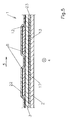
- FIG. 5 shows a cross section through a route belt 1 with three film strips 2,3,22. From the two film strips 2, 3 has the one made of signal-colored material, in the shown Embodiment, the carrier film 3, on its top 12 a transparent film 22 with the longitudinal pockets 7. The carrier film 3 also has one on its underside 13 transparent cover film 2. Carrier film 3 and transparent Cover film 2 are here over the entire surface of the adhesive layer 23 connected by gluing. The carrier film 3 is on her Bottom 13 printed with the printed text 17. Top 12 and Bottom 13 can in another embodiment also be interchanged. Both transparent foils are 2.22 laminated onto the carrier film 3. The in the longitudinal pockets 7 Seated plastic straps 8 are printed on the Bottom 13 opposite top 12 of the carrier film 3 arranged. They therefore do not hide the printed text 17th
Landscapes
- Engineering & Computer Science (AREA)
- General Engineering & Computer Science (AREA)
- Mechanical Engineering (AREA)
- Measurement And Recording Of Electrical Phenomena And Electrical Characteristics Of The Living Body (AREA)
- Structure Of Belt Conveyors (AREA)
- Control Of Motors That Do Not Use Commutators (AREA)
- Laying Of Electric Cables Or Lines Outside (AREA)
- Laminated Bodies (AREA)
Abstract
Description
- Fig.1.
- eine Draufsicht auf ein erfindungsgemässes, innenseitig bedrucktes Trassenband,
- Fig.2
- eine Explosionsdarstellung im Querschnitt durch das Trassenband der Fig.1,
- Fig.3
- einen Querschnitt durch das zusammengefügte Trassenband der Fig.2,
- Fig.4
- eine Draufsicht auf ein erfindungsgemäßes Trassenband, wobei die Deckfolie weggelassen und die Längstaschen durch Unterbrechung der Schraffur angedeutet sind,
- Fig.5
- ein weiteres Ausführungsbeispiel der Erfindung.
- 1
- Trassenband
- 2
- Deckfolie
- 3
- Trägerfolie
- 4
- Längsrichtung
- 5
- Querrichtung
- 6
- streifenförmige Verbindungszone
- 7
- Längstasche
- 8
- farbiges Kunststoffband
- 9
- Schwächungslinie
- 10
- Schwächungslinie
- 11
- Abstand der Schwächungslinien
- 12
- Oberseite der Trägerfolie
- 13
- Unterseite der Trägerfolie
- 14
- Unterseite der Deckfolie
- 15
- Oberseite der Deckfolie
- 16
- Länge des Trassenbandes
- 17
- Drucktext
- 18
- Breite des Trassenbandes
- 19
- Klebemittel
- 20
- Kaschierrichtung
- 22
- transparente Folie
- 23
- Klebeschicht
Claims (14)
- Trassenband (1) aus Kunststoff zur Verlegung in der Erde zur Warnung vor dem Vorhandensein erdverlegter Kabel oder Rohrleitungen, mit zwei übereinander liegenden Folienstreifen (2,3) von denen zumindest einer aus transparentem Material besteht, wobei beide Folienstreifen (2,3) in Längsrichtung (4) über streifenförmige Verbindungszonen (6) derart miteinander verbunden sind, daß zwischen den Verbindungszonen (6) Längstaschen (7) verbleiben, in welche farbiges Kunststoffband (8) eingezogen ist, dadurch gekennzeichnet, daß das Kunststoffband einstückig durchgehend ausgebildet ist, daß die streifenförmigen Verbindungszonen (6) in Längsrichtung (4) sowie in Querrichtung (5) praktisch durchgehend glatt, kräuselfrei sowie frei von Inhomogenitäten und Fehlstellen sind, und daß zumindest einer der Folienstreifen (2;3) nicht transparent, sondern aus signalfarbigem Material ist, und daß entlang der streifenförmigen Verbindungszonen (6) die Oberseite (12) eines der Folienstreifen (=Trägerfolie (3)) unmittelbar mit der Unterseite (14) des anderen Folienstreifens (=Deckfolie (2)) ununterbrochen über die gesamte Länge (16) des Trassenbandes (1) verbunden ist.
- Trassenband nach Anspruch 1, dadurch gekennzeichnet, daß die Trägerfolie (3) über die gesamte Länge (16) des Trassenbandes (1) frei von Sollbruchstellen ist.
- Trassenband nach Anspruch 1 oder 2, dadurch gekennzeichnet, daß die Reißfestigkeit des farbigen Kunststoffbandes (8) größer als die Reißfestigkeit der verbundenen Folienstreifen (2,3) ist.
- Trassenband nach Anspruch 3, dadurch gekennzeichnet, daß die übereinander liegenden Folienstreifen (2,3) entlang der streifenförmigen Verbindungszonen (6) miteinander verklebt sind.
- Trassenband nach Anspruch 4, dadurch gekennzeichnet, daß die übereinander liegenden Folienstreifen (2,3) mit einem Polyurethan-Kleber (19) verklebt sind, der ohne Abdampfen vernetzt und durch Luftfeuchtigkeit haftet.
- Trassenband nach einem der Ansprüche 1 bis 5, dadurch gekennzeichnet, daß die Deckfolie (2) aus transparentem Material besteht und auf der Innenseite bedruckt ist.
- Trassenband nach Anspruch 6, dadurch gekennzeichnet, daß der nicht transparente Folienstreifen (3) nicht bedruckt ist.
- Trassenband nach einem der Ansprüche 1 bis 7, dadurch gekennzeichnet, daß das Material des nicht transparenten Folienstreifens (3) in der Signalfarbe durchgefärbt ist.
- Trassenband nach einem der Ansprüche 1 bis 8, dadurch gekennzeichnet, daß die Folienstreifen (2,3) aus hochdichtem oder niedrigdichtem Polyethylen bestehen.
- Trassenband nach einem der Ansprüche 1 bis 9, dadurch gekennzeichnet, daß die Folienstreifen (2,3) streifenförmig unmittelbar miteinander verschweißt sind.
- Trassenband nach einem der Ansprüche 1 bis 10, dadurch gekennzeichnet, daß das Trassenband (1) lediglich aus den Folienstreifen (2,3) besteht.
- Trassenband nach einem der Ansprüche 1 bis 10, dadurch gekennzeichnet, daß von den beiden Folienstreifen (2,3) derjenige aus signalfarbigem Material auf seiner Oberseite (12) eine transparente Folie (22) mit den Längstaschen (7) aufweist, auf seiner Unterseite (13) bedruckt ist und dort eine ebenfalls transparente Folie (2) aufweist.
- Trassenband nach einem der Ansprüche 1 bis 12, dadurch gekennzeichnet, daß das Kunststoffband (8) quer zu seiner Längsrichtung (4) Schwächungslinien (9,10) aufweist, zwischen denen sich ungeschwächte Abschnitte von Kunststoffband (8) erstrecken.
- Trassenband nach Anspruch 13, dadurch gekennzeichnet, daß die Schwächungslinien (9,10) jeweils benachbarter Abschnitte einer der Längstaschen (7) um einen festgeschriebenen Mindestabstand (11) neben den Schwächungslinien (9,10) benachbarter Abschnitte der in Querrichtung (5) benachbarten Längstasche (7) liegen.
Applications Claiming Priority (2)
| Application Number | Priority Date | Filing Date | Title |
|---|---|---|---|
| DE29803773U DE29803773U1 (de) | 1998-03-06 | 1998-03-06 | Trassenband |
| DE29803773U | 1998-03-06 |
Publications (2)
| Publication Number | Publication Date |
|---|---|
| EP0940614A2 true EP0940614A2 (de) | 1999-09-08 |
| EP0940614A3 EP0940614A3 (de) | 2001-12-19 |
Family
ID=8053552
Family Applications (1)
| Application Number | Title | Priority Date | Filing Date |
|---|---|---|---|
| EP99104412A Withdrawn EP0940614A3 (de) | 1998-03-06 | 1999-03-05 | Trassenband |
Country Status (2)
| Country | Link |
|---|---|
| EP (1) | EP0940614A3 (de) |
| DE (1) | DE29803773U1 (de) |
Cited By (1)
| Publication number | Priority date | Publication date | Assignee | Title |
|---|---|---|---|---|
| EP3454439A1 (de) | 2017-09-12 | 2019-03-13 | Heidelberger Beton GmbH | Verfahren zum verlegen von stromkabeln |
Families Citing this family (1)
| Publication number | Priority date | Publication date | Assignee | Title |
|---|---|---|---|---|
| WO2023088603A1 (en) * | 2021-11-19 | 2023-05-25 | Canco Hungary Investment Ltd. | Lightweight rollable power cable cover |
Citations (1)
| Publication number | Priority date | Publication date | Assignee | Title |
|---|---|---|---|---|
| US3581703A (en) * | 1969-04-28 | 1971-06-01 | Robert C Hosack | Warning tape for underground installations |
Family Cites Families (5)
| Publication number | Priority date | Publication date | Assignee | Title |
|---|---|---|---|---|
| US4699838A (en) * | 1985-12-03 | 1987-10-13 | Reef Industries, Inc. | Reinforced metallic and polymer tape |
| SE500440C2 (sv) * | 1985-12-03 | 1994-06-27 | Reef Ind Inc | Kantförslutet märkband innehållande ett metallfolieskikt |
| ES2036708T3 (es) * | 1987-10-28 | 1993-06-01 | Plymouth Francaise | Dispositivo avisador de canalizaciones enterradas. |
| US4879162A (en) * | 1988-03-24 | 1989-11-07 | Hansen Sr James B | Buryable warning tape |
| DE9116991U1 (de) * | 1991-08-27 | 1995-01-05 | Kelmaplast G. Kellermann GmbH, 45549 Sprockhövel | Warnband |
-
1998
- 1998-03-06 DE DE29803773U patent/DE29803773U1/de not_active Expired - Lifetime
-
1999
- 1999-03-05 EP EP99104412A patent/EP0940614A3/de not_active Withdrawn
Patent Citations (1)
| Publication number | Priority date | Publication date | Assignee | Title |
|---|---|---|---|---|
| US3581703A (en) * | 1969-04-28 | 1971-06-01 | Robert C Hosack | Warning tape for underground installations |
Cited By (1)
| Publication number | Priority date | Publication date | Assignee | Title |
|---|---|---|---|---|
| EP3454439A1 (de) | 2017-09-12 | 2019-03-13 | Heidelberger Beton GmbH | Verfahren zum verlegen von stromkabeln |
Also Published As
| Publication number | Publication date |
|---|---|
| EP0940614A3 (de) | 2001-12-19 |
| DE29803773U1 (de) | 1999-07-22 |
Similar Documents
| Publication | Publication Date | Title |
|---|---|---|
| WO1992016431A1 (de) | Schlauchbeutelverpackung | |
| DE10201480B4 (de) | Stretchfolie | |
| DE2737244C2 (de) | Endlospapierbahn zur Herstellung von Faltbriefumschlägen mit anhängenden Einlagen | |
| DE2806538A1 (de) | Verfahren zur herstellung einer kette von tueten | |
| DE69203583T2 (de) | Ummantelung von Rohren in einem Graben. | |
| EP1777167B1 (de) | Folienverpackungsbeutel | |
| DE2844523A1 (de) | Bewaesserungseinrichtung | |
| DE8803229U1 (de) | Verpackung für Gegenstände, insbesondere von Quaderform | |
| DE9018119U1 (de) | Bituminöse Schweißbahn für Verwahrungszwecke von Bauten | |
| DE2000833A1 (de) | Zusammenhaengender Verband mit Briefumschlaegen | |
| EP0193605B2 (de) | Folienmaterial zum kontrollierbar dichten trennen der auf seinen beiden seiten befindlichen bereiche | |
| DE29803773U1 (de) | Trassenband | |
| EP3695144B1 (de) | Dichtungsstrang, insbesondere zur verarbeitung als endlosstrang | |
| EP0106328A2 (de) | Rohrförmiges Isoliermaterial | |
| DE19636511C2 (de) | Zugbandbeutel | |
| DE60009418T2 (de) | Stossdämpfendes Verpackungsmaterial | |
| EP0509197B1 (de) | Folientaschen-Buch | |
| EP0530467B1 (de) | Warnband | |
| EP1605093B1 (de) | Markisenbahn mit Dehnungsbegrenzung | |
| CH682228A5 (de) | ||
| EP0554556B1 (de) | Folientasche | |
| EP1225133B1 (de) | Verpackung von Mineralwolle-Lamellenplatten | |
| EP0486665A1 (de) | Verfahren zur herstellung eines offnungen aufweisenden kunststofffolie, eine nach dem verfahren hergestellte verpackungsfolie und ein verfahren zum v | |
| AT525167B1 (de) | Klebeecke | |
| EP3877169B1 (de) | Bahnmaterial aus gewebe und verfahren zu seiner herstellung |
Legal Events
| Date | Code | Title | Description |
|---|---|---|---|
| PUAI | Public reference made under article 153(3) epc to a published international application that has entered the european phase |
Free format text: ORIGINAL CODE: 0009012 |
|
| AK | Designated contracting states |
Kind code of ref document: A2 Designated state(s): AT BE CH CY DE DK ES FI FR GB GR IE IT LI LU MC NL PT SE Kind code of ref document: A2 Designated state(s): AT BE CH DE ES FR GB IT LI |
|
| AX | Request for extension of the european patent |
Free format text: AL;LT;LV;MK;RO;SI |
|
| PUAL | Search report despatched |
Free format text: ORIGINAL CODE: 0009013 |
|
| AK | Designated contracting states |
Kind code of ref document: A3 Designated state(s): AT BE CH CY DE DK ES FI FR GB GR IE IT LI LU MC NL PT SE |
|
| AX | Request for extension of the european patent |
Free format text: AL;LT;LV;MK;RO;SI |
|
| 17P | Request for examination filed |
Effective date: 20020321 |
|
| AKX | Designation fees paid |
Free format text: AT BE CH DE ES FR GB IT LI |
|
| TPAD | Observations filed by third parties |
Free format text: ORIGINAL CODE: EPIDOS TIPA |
|
| 17Q | First examination report despatched |
Effective date: 20030818 |
|
| 17Q | First examination report despatched |
Effective date: 20030818 |
|
| RIC1 | Information provided on ipc code assigned before grant |
Ipc: F16L 1/11 20060101ALI20121206BHEP Ipc: H02G 9/02 20060101AFI20121206BHEP |
|
| GRAP | Despatch of communication of intention to grant a patent |
Free format text: ORIGINAL CODE: EPIDOSNIGR1 |
|
| INTG | Intention to grant announced |
Effective date: 20130710 |
|
| STAA | Information on the status of an ep patent application or granted ep patent |
Free format text: STATUS: THE APPLICATION IS DEEMED TO BE WITHDRAWN |
|
| 18D | Application deemed to be withdrawn |
Effective date: 20131001 |