EP0940622A1 - Moteur à combustion interne - Google Patents
Moteur à combustion interne Download PDFInfo
- Publication number
- EP0940622A1 EP0940622A1 EP99890065A EP99890065A EP0940622A1 EP 0940622 A1 EP0940622 A1 EP 0940622A1 EP 99890065 A EP99890065 A EP 99890065A EP 99890065 A EP99890065 A EP 99890065A EP 0940622 A1 EP0940622 A1 EP 0940622A1
- Authority
- EP
- European Patent Office
- Prior art keywords
- oil
- oil pump
- pair
- gear
- gears
- Prior art date
- Legal status (The legal status is an assumption and is not a legal conclusion. Google has not performed a legal analysis and makes no representation as to the accuracy of the status listed.)
- Granted
Links
- 238000002485 combustion reaction Methods 0.000 title claims abstract description 12
- 230000001419 dependent effect Effects 0.000 claims description 3
- 239000003921 oil Substances 0.000 description 52
- 238000007726 management method Methods 0.000 description 3
- 238000001816 cooling Methods 0.000 description 1
- 238000010586 diagram Methods 0.000 description 1
- 238000006073 displacement reaction Methods 0.000 description 1
- 230000000694 effects Effects 0.000 description 1
- 238000005516 engineering process Methods 0.000 description 1
- 238000005461 lubrication Methods 0.000 description 1
- 238000004519 manufacturing process Methods 0.000 description 1
- 239000010742 number 1 fuel oil Substances 0.000 description 1
- 238000005192 partition Methods 0.000 description 1
- 238000005086 pumping Methods 0.000 description 1
- 230000000717 retained effect Effects 0.000 description 1
Images

Classifications
-
- F—MECHANICAL ENGINEERING; LIGHTING; HEATING; WEAPONS; BLASTING
- F01—MACHINES OR ENGINES IN GENERAL; ENGINE PLANTS IN GENERAL; STEAM ENGINES
- F01M—LUBRICATING OF MACHINES OR ENGINES IN GENERAL; LUBRICATING INTERNAL COMBUSTION ENGINES; CRANKCASE VENTILATING
- F01M1/00—Pressure lubrication
- F01M1/16—Controlling lubricant pressure or quantity
-
- F—MECHANICAL ENGINEERING; LIGHTING; HEATING; WEAPONS; BLASTING
- F01—MACHINES OR ENGINES IN GENERAL; ENGINE PLANTS IN GENERAL; STEAM ENGINES
- F01M—LUBRICATING OF MACHINES OR ENGINES IN GENERAL; LUBRICATING INTERNAL COMBUSTION ENGINES; CRANKCASE VENTILATING
- F01M1/00—Pressure lubrication
- F01M1/12—Closed-circuit lubricating systems not provided for in groups F01M1/02 - F01M1/10
- F01M2001/123—Closed-circuit lubricating systems not provided for in groups F01M1/02 - F01M1/10 using two or more pumps
Definitions
- the present invention relates to an internal combustion engine with at least one pair of gears meshing with each other, at least one Intake opening and at least one discharge opening.
- Oil pumps for internal combustion engines which are provided in particular in motor vehicles, are mostly designed as gear pumps. They consist of a pair of gears that mesh with each other, the oil production is caused by the displacement of the teeth. The The pumping effect of such gear pumps depends essentially linearly on the speed with which these gear pumps are driven. Since the drive is generally direct The delivery rate is therefore essentially proportional via the internal combustion engine itself to the speed of the internal combustion engine. The for the operation of the internal combustion engine However, the amount of oil required is not linearly dependent on the speed. This means that in some speed ranges, especially at low speeds, the danger of lack of oil supply, while in other speed ranges a relatively large one Quantity must be controlled via pressure relief valves.
- the object of the present invention is to provide an oil pump of the type described in the introduction to further develop such that these disadvantages are avoided.
- these objects are achieved in that at least two gear pairs are provided are that a first common shaft is provided, on each of which a first gear A pair of gears is arranged, and that means are provided to the individual To apply gear pairs with oil depending on the required oil flow.
- the solution according to the invention is designed so that with a relatively low oil requirement only one Gear pair takes over the actual promotion. At maximum oil demand, everyone will Gear pairs used parallel to each other for conveying.
- Gear pair is assigned its own suction opening and its own discharge opening and if a valve is provided to selectively connect at least one suction opening with the to connect the associated discharge opening.
- the idling gear pair (s) is / are operated in circulation and essentially without pressure, so that cooling and Lubrication is guaranteed, but with the exception of friction losses, no drive torque is required for the movement of the gears.
- a control valve is provided to selectively supply the individual gear pairs with oil, and that the oil pressure in the discharge line as a control pressure for this switching valve is used.
- an electronic Control device is provided to apply oil to the individual gear pairs.
- the oil pump according to the invention can be intelligently used by engine management being controlled. In this way it is also possible to meet any additional oil requirements cover, for example, from a device for changing the setting angle Camshaft results.
- a Intake line 11 which is in a reservoir 12, such as the oil pan one not closer Internal combustion engine shown, leads, connected to the first intake port 8a.
- the first discharge port 8b is provided with an oil supply line 13 to be lubricated Leads components, connected. Furthermore, in this position of the valve 10 second suction opening 9a and the second discharge opening 9b connected to each other so that the gear pair 6a, 6b is operated in the short circuit.
- the control of the valve 10 can be carried out according to the invention in such a way that at low Oil pressure, the control valve 10 is in any case in the third position. If a first is exceeded Pressure limit can be switched to the second state, and if this pressure is reached again, can be switched to the third state. As an alternative, however, the switchover of the valve 10 can also be carried out via the engine management respectively. This has the additional advantage that, for example, during a cold start or in other operating conditions in which a large oil output is required, the Valve 10 can be brought into the third position. Even if additional oil consumption sources, how certain actuators are switched on, that can Engine management already provide a higher oil pressure in advance.
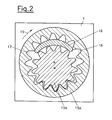
- FIG. 2 A possible embodiment of an oil pump according to the invention is shown in FIG. 2.
- a ring gear 15a and a ring gear 15a are engaged in a housing 1 standing gear 15b provided.
- the gears 15a and 15b are eccentric to one another, to be engaged.
- a guide element 16 is provided, which separates the suction chamber 17 from the discharge chamber 18. It will be there assumed that the gears 15a, 15b rotate in the direction of arrow 19.
- the curve 20 corresponds to the disproportionately increasing Oil requirement of the internal combustion engine.
- the solid line 21 corresponds to the Oil flow rate of a known oil pump.
- the graduated line 22 shown broken is the characteristic curve of an oil pump according to the invention. 3 shows that the performance of the known oil pump according to the characteristic 21 is essential increases faster than oil demand (curve 20). Although in the low speed range Area 23, in which the oil flow rate is too low with the known pump, is the Oil flow rate at higher speeds much larger than the actual demand.
- the present invention makes it possible to create an oil pump that is a better one Oil supply to the engine is guaranteed, and the other hand a lower one Has power requirements.
Landscapes
- Engineering & Computer Science (AREA)
- Mechanical Engineering (AREA)
- General Engineering & Computer Science (AREA)
- Rotary Pumps (AREA)
- Details And Applications Of Rotary Liquid Pumps (AREA)
- Lubrication Of Internal Combustion Engines (AREA)
Applications Claiming Priority (2)
| Application Number | Priority Date | Filing Date | Title |
|---|---|---|---|
| AT0034898A AT407563B (de) | 1998-02-26 | 1998-02-26 | Ölpumpe für eine brennkraftmaschine mit innerer verbrennung |
| AT34898 | 1998-02-26 |
Publications (2)
| Publication Number | Publication Date |
|---|---|
| EP0940622A1 true EP0940622A1 (fr) | 1999-09-08 |
| EP0940622B1 EP0940622B1 (fr) | 2003-05-28 |
Family
ID=3488236
Family Applications (1)
| Application Number | Title | Priority Date | Filing Date |
|---|---|---|---|
| EP99890065A Expired - Lifetime EP0940622B1 (fr) | 1998-02-26 | 1999-02-25 | Pompe à huile |
Country Status (4)
| Country | Link |
|---|---|
| US (1) | US6206651B1 (fr) |
| EP (1) | EP0940622B1 (fr) |
| AT (2) | AT407563B (fr) |
| DE (1) | DE59905695D1 (fr) |
Cited By (1)
| Publication number | Priority date | Publication date | Assignee | Title |
|---|---|---|---|---|
| EP1693553A3 (fr) * | 2005-02-18 | 2010-05-26 | Dr. Ing. h.c. F. Porsche AG | Méthode pour contrôler une pompe à huile d'un moteur |
Families Citing this family (3)
| Publication number | Priority date | Publication date | Assignee | Title |
|---|---|---|---|---|
| US20110129359A1 (en) * | 2009-11-30 | 2011-06-02 | Caterpillar Inc. | Variable output pump |
| KR101326850B1 (ko) * | 2012-10-04 | 2013-11-11 | 기아자동차주식회사 | 오일펌프 제어 시스템 및 방법 |
| KR101680648B1 (ko) * | 2015-09-10 | 2016-11-30 | 명화공업주식회사 | 듀얼 펌프 시스템 |
Citations (5)
| Publication number | Priority date | Publication date | Assignee | Title |
|---|---|---|---|---|
| FR498749A (fr) * | 1916-01-18 | 1920-01-21 | Sunbeam Motor Car Co Ltd | Perfectionnements aux systèmes de graissage pour moteurs à combustion interne |
| JPS5926692A (ja) * | 1982-07-31 | 1984-02-10 | Isuzu Motors Ltd | 車両用潤滑油系の運転制御方法 |
| DE3639122A1 (de) * | 1986-11-15 | 1987-11-19 | Mtu Friedrichshafen Gmbh | Pumpenanordnung |
| DE3814750A1 (de) * | 1988-04-30 | 1989-02-02 | Mtu Friedrichshafen Gmbh | Einrichtung zum antrieb einer schmiermittelpumpe einer brennkraftmaschine |
| DE19525890A1 (de) * | 1995-07-15 | 1997-01-16 | Ingelheim Peter Graf Von | Regelsystem zur stufenlosen Drehzahlregelung von Arbeitsmaschinen, insbesondere von Fahrzeuglichtmaschinen und Schmierölpumpen |
Family Cites Families (11)
| Publication number | Priority date | Publication date | Assignee | Title |
|---|---|---|---|---|
| US3068795A (en) * | 1956-10-18 | 1962-12-18 | Borg Warner | Hydraulic power system |
| US3385217A (en) * | 1966-02-21 | 1968-05-28 | Marcus J. Bles | Hydraulic pressure booster |
| US4002027A (en) * | 1973-10-01 | 1977-01-11 | Tyrone Hydraulics, Inc. | Multiple pump control system |
| DE3139187A1 (de) * | 1981-10-02 | 1983-04-21 | Volkswagenwerk Ag, 3180 Wolfsburg | "zahnradpumpe zur foerderung von fluessigkeiten, insbesondere schmieroelpumpe fuer brennkraftmaschinen" |
| DE3666606D1 (en) * | 1985-05-09 | 1989-11-30 | Barmag Barmer Maschf | Variable capacity pump |
| DE3614819A1 (de) * | 1986-05-02 | 1987-11-12 | Kloeckner Humboldt Deutz Ag | Innenverzahnte doppelpumpe mit gemeinsamer ansaugung und getrennten druckausgaengen |
| DE3743261A1 (de) * | 1987-12-19 | 1989-06-29 | Kloeckner Humboldt Deutz Ag | Doppelpumpe fuer ein foerdermedium mit unterschiedlichen foerdermengen und foerderdruecken |
| DE3837599A1 (de) * | 1988-11-05 | 1990-05-10 | Daimler Benz Ag | Zahnradpumpe mit zwei im pumpengehaeuse nebeneinander angeordneten zahnradpaaren |
| JP2776882B2 (ja) * | 1989-04-27 | 1998-07-16 | 株式会社ユニシアジェックス | ポンプ装置 |
| DE4129854A1 (de) * | 1991-09-07 | 1993-03-11 | Teves Gmbh Alfred | Zahnradpumpe mit einer nichtlinear von der drehzahl abhaengenden foerdermenge |
| DE19622688A1 (de) * | 1996-06-05 | 1997-12-11 | Bayerische Motoren Werke Ag | Brennkraftmaschine mit mittels schmierölversorgten gesonderten Hydraulikkreisen |
-
1998
- 1998-02-26 AT AT0034898A patent/AT407563B/de not_active IP Right Cessation
-
1999
- 1999-02-25 DE DE59905695T patent/DE59905695D1/de not_active Expired - Lifetime
- 1999-02-25 US US09/257,249 patent/US6206651B1/en not_active Expired - Fee Related
- 1999-02-25 AT AT99890065T patent/ATE241775T1/de not_active IP Right Cessation
- 1999-02-25 EP EP99890065A patent/EP0940622B1/fr not_active Expired - Lifetime
Patent Citations (5)
| Publication number | Priority date | Publication date | Assignee | Title |
|---|---|---|---|---|
| FR498749A (fr) * | 1916-01-18 | 1920-01-21 | Sunbeam Motor Car Co Ltd | Perfectionnements aux systèmes de graissage pour moteurs à combustion interne |
| JPS5926692A (ja) * | 1982-07-31 | 1984-02-10 | Isuzu Motors Ltd | 車両用潤滑油系の運転制御方法 |
| DE3639122A1 (de) * | 1986-11-15 | 1987-11-19 | Mtu Friedrichshafen Gmbh | Pumpenanordnung |
| DE3814750A1 (de) * | 1988-04-30 | 1989-02-02 | Mtu Friedrichshafen Gmbh | Einrichtung zum antrieb einer schmiermittelpumpe einer brennkraftmaschine |
| DE19525890A1 (de) * | 1995-07-15 | 1997-01-16 | Ingelheim Peter Graf Von | Regelsystem zur stufenlosen Drehzahlregelung von Arbeitsmaschinen, insbesondere von Fahrzeuglichtmaschinen und Schmierölpumpen |
Non-Patent Citations (1)
| Title |
|---|
| PATENT ABSTRACTS OF JAPAN vol. 008, no. 120 (M - 300) 6 June 1984 (1984-06-06) * |
Cited By (1)
| Publication number | Priority date | Publication date | Assignee | Title |
|---|---|---|---|---|
| EP1693553A3 (fr) * | 2005-02-18 | 2010-05-26 | Dr. Ing. h.c. F. Porsche AG | Méthode pour contrôler une pompe à huile d'un moteur |
Also Published As
| Publication number | Publication date |
|---|---|
| ATA34898A (de) | 2000-08-15 |
| US6206651B1 (en) | 2001-03-27 |
| ATE241775T1 (de) | 2003-06-15 |
| DE59905695D1 (de) | 2003-07-03 |
| EP0940622B1 (fr) | 2003-05-28 |
| AT407563B (de) | 2001-04-25 |
Similar Documents
| Publication | Publication Date | Title |
|---|---|---|
| EP0712997B1 (fr) | Pompe à engrenages internes avec réglage de l'aspiration | |
| DE2240018C3 (de) | Ein- oder mehrstufiger Flügelzellen- oder Schraubenkolbenverdichter | |
| DE69832071T2 (de) | Steuervorrichtung für mehrfachpumpen | |
| DE4227332C2 (de) | Schraubenverdichter | |
| EP0362906B1 (fr) | Pompe à engrènement interne | |
| DE10213598A1 (de) | Ölpumpe für eine Brennkraftmaschine und Verfahren zum Betrieb derselben | |
| DE3600640C2 (fr) | ||
| DE19502235A1 (de) | Ölversorgungssystem | |
| EP1070848A1 (fr) | Machine à déplacement positif pour des fluides compressibles | |
| DE2302518A1 (de) | Geschwindigkeitswechselgetriebe | |
| DE2140569A1 (de) | Innenachsige rotationskolbenmaschine mit kaemmeingriff | |
| DE4308506A1 (de) | Ölpumpensystem | |
| EP1463888B1 (fr) | Dispositif pour reguler la pression de pompes hydrauliques | |
| DE511495C (de) | Fluessigkeitsgetriebe | |
| EP1586785A2 (fr) | Arrangement et méthode d'accouplement d'un compresseur d'air à l'arbre d'entraínement d'un moteur de combustion | |
| DE69826358T2 (de) | Steuerventil einer Ölpumpe | |
| EP0940622B1 (fr) | Pompe à huile | |
| DE10159147A1 (de) | Hydraulische Zahnradpumpe | |
| WO1986006797A2 (fr) | Pompe a capacite variable | |
| DE879942C (de) | Stufenlos regelbares hydraulisches Getriebe | |
| EP1859170B1 (fr) | Machine a piston rotatif | |
| DE102006056844A1 (de) | Innenzahnradpumpe | |
| DE20305937U1 (de) | Pumpe mit integriertem Hydraulik-Motor | |
| WO2005019650A1 (fr) | Pompe a rotor a volume variable | |
| DD142741A1 (de) | Einrichtung zur steuerung des fluidstroms von rotationskolbenmaschinen,insbesondere zahnradpumpen |
Legal Events
| Date | Code | Title | Description |
|---|---|---|---|
| PUAI | Public reference made under article 153(3) epc to a published international application that has entered the european phase |
Free format text: ORIGINAL CODE: 0009012 |
|
| AK | Designated contracting states |
Kind code of ref document: A1 Designated state(s): AT DE FR GB IT |
|
| AX | Request for extension of the european patent |
Free format text: AL;LT;LV;MK;RO;SI |
|
| 17P | Request for examination filed |
Effective date: 19990920 |
|
| AKX | Designation fees paid |
Free format text: AT DE FR GB IT |
|
| 17Q | First examination report despatched |
Effective date: 20000925 |
|
| RTI1 | Title (correction) |
Free format text: OIL PUMP |
|
| GRAG | Despatch of communication of intention to grant |
Free format text: ORIGINAL CODE: EPIDOS AGRA |
|
| GRAG | Despatch of communication of intention to grant |
Free format text: ORIGINAL CODE: EPIDOS AGRA |
|
| GRAH | Despatch of communication of intention to grant a patent |
Free format text: ORIGINAL CODE: EPIDOS IGRA |
|
| GRAH | Despatch of communication of intention to grant a patent |
Free format text: ORIGINAL CODE: EPIDOS IGRA |
|
| GRAA | (expected) grant |
Free format text: ORIGINAL CODE: 0009210 |
|
| AK | Designated contracting states |
Designated state(s): AT DE FR GB IT |
|
| REG | Reference to a national code |
Ref country code: GB Ref legal event code: FG4D Free format text: NOT ENGLISH |
|
| GBT | Gb: translation of ep patent filed (gb section 77(6)(a)/1977) | ||
| REF | Corresponds to: |
Ref document number: 59905695 Country of ref document: DE Date of ref document: 20030703 Kind code of ref document: P |
|
| PG25 | Lapsed in a contracting state [announced via postgrant information from national office to epo] |
Ref country code: AT Free format text: LAPSE BECAUSE OF NON-PAYMENT OF DUE FEES Effective date: 20040225 |
|
| ET | Fr: translation filed | ||
| PLBE | No opposition filed within time limit |
Free format text: ORIGINAL CODE: 0009261 |
|
| STAA | Information on the status of an ep patent application or granted ep patent |
Free format text: STATUS: NO OPPOSITION FILED WITHIN TIME LIMIT |
|
| 26N | No opposition filed |
Effective date: 20040302 |
|
| GBPC | Gb: european patent ceased through non-payment of renewal fee |
Effective date: 20070225 |
|
| PGFP | Annual fee paid to national office [announced via postgrant information from national office to epo] |
Ref country code: IT Payment date: 20070523 Year of fee payment: 9 |
|
| PG25 | Lapsed in a contracting state [announced via postgrant information from national office to epo] |
Ref country code: GB Free format text: LAPSE BECAUSE OF NON-PAYMENT OF DUE FEES Effective date: 20070225 |
|
| PGFP | Annual fee paid to national office [announced via postgrant information from national office to epo] |
Ref country code: FR Payment date: 20070223 Year of fee payment: 9 |
|
| PGFP | Annual fee paid to national office [announced via postgrant information from national office to epo] |
Ref country code: GB Payment date: 20060223 Year of fee payment: 8 |
|
| REG | Reference to a national code |
Ref country code: FR Ref legal event code: ST Effective date: 20081031 |
|
| PG25 | Lapsed in a contracting state [announced via postgrant information from national office to epo] |
Ref country code: FR Free format text: LAPSE BECAUSE OF NON-PAYMENT OF DUE FEES Effective date: 20080229 |
|
| PG25 | Lapsed in a contracting state [announced via postgrant information from national office to epo] |
Ref country code: IT Free format text: LAPSE BECAUSE OF NON-PAYMENT OF DUE FEES Effective date: 20080225 |
|
| PGFP | Annual fee paid to national office [announced via postgrant information from national office to epo] |
Ref country code: DE Payment date: 20100204 Year of fee payment: 12 |
|
| REG | Reference to a national code |
Ref country code: DE Ref legal event code: R119 Ref document number: 59905695 Country of ref document: DE Effective date: 20110901 |
|
| PG25 | Lapsed in a contracting state [announced via postgrant information from national office to epo] |
Ref country code: DE Free format text: LAPSE BECAUSE OF NON-PAYMENT OF DUE FEES Effective date: 20110901 |