EP0940623B1 - Dispositif de contrôle d'une zone protégée - Google Patents
Dispositif de contrôle d'une zone protégée Download PDFInfo
- Publication number
- EP0940623B1 EP0940623B1 EP99103434A EP99103434A EP0940623B1 EP 0940623 B1 EP0940623 B1 EP 0940623B1 EP 99103434 A EP99103434 A EP 99103434A EP 99103434 A EP99103434 A EP 99103434A EP 0940623 B1 EP0940623 B1 EP 0940623B1
- Authority
- EP
- European Patent Office
- Prior art keywords
- monitoring unit
- switch
- connection
- output
- accordance
- Prior art date
- Legal status (The legal status is an assumption and is not a legal conclusion. Google has not performed a legal analysis and makes no representation as to the accuracy of the status listed.)
- Expired - Lifetime
Links
- 238000012544 monitoring process Methods 0.000 title claims description 63
- 230000005540 biological transmission Effects 0.000 claims description 13
- 230000006870 function Effects 0.000 description 8
- 238000012806 monitoring device Methods 0.000 description 7
- 230000003213 activating effect Effects 0.000 description 2
- 230000001960 triggered effect Effects 0.000 description 2
- 230000008878 coupling Effects 0.000 description 1
- 238000010168 coupling process Methods 0.000 description 1
- 238000005859 coupling reaction Methods 0.000 description 1
- 230000007547 defect Effects 0.000 description 1
- 238000005516 engineering process Methods 0.000 description 1
- 230000007274 generation of a signal involved in cell-cell signaling Effects 0.000 description 1
- 238000004519 manufacturing process Methods 0.000 description 1
- 238000000034 method Methods 0.000 description 1
- 230000003287 optical effect Effects 0.000 description 1
- 230000000149 penetrating effect Effects 0.000 description 1
- 230000001681 protective effect Effects 0.000 description 1
- 230000011664 signaling Effects 0.000 description 1
Images

Classifications
-
- F—MECHANICAL ENGINEERING; LIGHTING; HEATING; WEAPONS; BLASTING
- F16—ENGINEERING ELEMENTS AND UNITS; GENERAL MEASURES FOR PRODUCING AND MAINTAINING EFFECTIVE FUNCTIONING OF MACHINES OR INSTALLATIONS; THERMAL INSULATION IN GENERAL
- F16P—SAFETY DEVICES IN GENERAL; SAFETY DEVICES FOR PRESSES
- F16P3/00—Safety devices acting in conjunction with the control or operation of a machine; Control arrangements requiring the simultaneous use of two or more parts of the body
- F16P3/12—Safety devices acting in conjunction with the control or operation of a machine; Control arrangements requiring the simultaneous use of two or more parts of the body with means, e.g. feelers, which in case of the presence of a body part of a person in or near the danger zone influence the control or operation of the machine
- F16P3/14—Safety devices acting in conjunction with the control or operation of a machine; Control arrangements requiring the simultaneous use of two or more parts of the body with means, e.g. feelers, which in case of the presence of a body part of a person in or near the danger zone influence the control or operation of the machine the means being photocells or other devices sensitive without mechanical contact
- F16P3/144—Safety devices acting in conjunction with the control or operation of a machine; Control arrangements requiring the simultaneous use of two or more parts of the body with means, e.g. feelers, which in case of the presence of a body part of a person in or near the danger zone influence the control or operation of the machine the means being photocells or other devices sensitive without mechanical contact using light grids
-
- F—MECHANICAL ENGINEERING; LIGHTING; HEATING; WEAPONS; BLASTING
- F16—ENGINEERING ELEMENTS AND UNITS; GENERAL MEASURES FOR PRODUCING AND MAINTAINING EFFECTIVE FUNCTIONING OF MACHINES OR INSTALLATIONS; THERMAL INSULATION IN GENERAL
- F16P—SAFETY DEVICES IN GENERAL; SAFETY DEVICES FOR PRESSES
- F16P3/00—Safety devices acting in conjunction with the control or operation of a machine; Control arrangements requiring the simultaneous use of two or more parts of the body
- F16P3/12—Safety devices acting in conjunction with the control or operation of a machine; Control arrangements requiring the simultaneous use of two or more parts of the body with means, e.g. feelers, which in case of the presence of a body part of a person in or near the danger zone influence the control or operation of the machine
Definitions
- the present invention relates to a device for monitoring a Protection area with a monitoring unit for detecting a in the Protected area intruding object, the monitoring unit has at least one exit at which an object enters the protection area a control signal to control a monitored Device, in particular a switching signal for switching off the device, can be generated, and with at least one connection for one Switch, especially for an emergency stop switch, through which the device can also be controlled, in particular switched off.
- the monitoring unit In order to switch off the monitored in such devices Setup by generating a corresponding shutdown signal the monitoring unit also switches off manually, for example to be possible via an emergency stop switch, for example the switching output of the monitoring unit and the output of the Emergency switch supplied to a common switching unit through which both the signals coming from the emergency stop switch and those from signals coming from the switching output of the monitoring unit become.
- an emergency stop switch for example the switching output of the monitoring unit and the output of the Emergency switch supplied to a common switching unit through which both the signals coming from the emergency stop switch and those from signals coming from the switching output of the monitoring unit become.
- an emergency stop switch for example the switching output of the monitoring unit and the output of the Emergency switch supplied to a common switching unit through which both the signals coming from the emergency stop switch and those from signals coming from the switching output of the monitoring unit become.
- Corresponding switch-off signal is generated and sent to the device to be monitored forwarded so that it is switched off.
- the disadvantage here is that the switching unit determined depending on the application Must comply with safety instructions and therefore usually a not negligible share of the total cost of a corresponding monitoring device. Furthermore exists through the additional interposition of a switching unit in the Switch-off path the risk that the individual elements are wrong with each other are interconnected, so that the functionality of the device is not would be guaranteed. However, this is precisely what must be said for the above safety-related monitoring devices must be excluded.
- the switching unit Since the switching unit is usually at a relatively large distance from the monitoring device is arranged, but the emergency stop switch close to the potential danger point, d. H. in the area to be monitored Device must be provided, has the connecting line often a relatively long length between the emergency stop switch and the switching unit. This is disadvantageous because it reduces the cost of the line that meets the given Security requirements must be increased and furthermore the risk of damage to the line increases.
- the object of the invention is a device of the aforementioned Specify type that is easy and inexpensive to manufacture and at incorrect connection of the individual components is practically impossible is.
- the switch connected to the monitoring unit for example an emergency stop
- the functionality of the monitoring unit a corresponding control signal for activating those to be monitored Generating facility used.
- an additional, safe switching unit for checking the output signals of the Monitoring unit and the emergency stop switch are dispensed with, since that control signal present at the output of the monitoring unit both at Detect an object entering the protected area as well by operating the emergency stop button through the same section of the Monitoring unit is generated.
- the connecting line with a device according to the invention between emergency stop switch and monitoring unit relative be kept short.
- the costs for the monitoring line reduced and secondly the risk of damage the line can be reduced.
- the terms "emergency stop switch” and “switch off” are used, this is only meant as an example.
- the idea of the invention is not limited to these explanations, but also includes the cases where, for example, instead of a shutdown signal, a control signal is generated by which the Device can be controlled accordingly.
- a control signal is generated by which the Device can be controlled accordingly.
- the emergency stop switch can also act as a continuously switching switch, so here not just the switching states “on / off” but continuous Switching states can be possible.
- the monitoring unit has a variety of inputs to which a variety of Switches can be connected.
- the invention is therefore not based on use a single switch is limited, but there can be several Switches can be provided, for example at different locations are provided for generating the switching signal.
- the monitoring unit is preferably a non-contact monitoring unit, especially designed as a light grid.
- contactless Acting monitoring units are particularly advantageous because they are in the Usually work maintenance-free and when an object penetrates into the monitoring area are not mechanically stressed, whereby the likelihood of a defect can be reduced.
- the monitoring unit it is also possible to use the monitoring unit as mechanically responsive monitoring unit, especially with a Step mat for detecting those entering the monitoring area Objects, or in any other suitable way.
- the monitoring unit has a transmission element for transmitting a transmission signal and a reception signal for receiving the from the transmission element emitted transmission signal is formed, the output, on which the switching signal is generated, provided on the receiving element is.
- the connection is preferred as the input of the receiving element educated.
- connection as the input of the receiving element is a particularly simple embodiment of the invention Device possible because in this way all connections to the Receiving element are provided (input for the switch and output for switching signal generation). A separate connection between the Transmitting and receiving elements are not required for this training.
- connection as the input of the transmission element is formed and that the transmitting element with the receiving element for the transmission of control signals, in particular via a Bus line, is coupled.
- This training is particularly advantageous if the electrical input signals are already in the receiving element through other functions, such as external device monitoring, command device, Lamp outputs, switching outputs and so on are occupied.
- the corresponding signal inputs are often on the transmitter element, to which the switch can be connected, unused to disposal.
- Output via a bus line with a safe controller with bus connection connected via which the device to be monitored can be controlled is.
- This embodiment is particularly useful if that Transmitting element connected to the receiving element via a bus line is so that the switch is connected to an input of the transmission element can be. In principle, however, this training is also then possible if the switch at an input of the receiving element or both a switch on the receiving element and a switch on the transmission element are connected.
- the Connection as a multi-function connection, for example for connecting one Restart button, a cycle control, a mode selector switch, one Learn button or for operation as a switching or signaling output or as Synchronization connection for several interconnected monitoring units educated.
- multi-function connections can by appropriate configuration of the monitoring unit both as Input and output can be switched and used, so that each According to the invention, an emergency stop switch on one or more, if required the multifunction connections can be connected. This can the security of a corresponding device can be further increased.
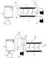
- Fig. 1 shows a contact light acting as a light grid Monitoring unit 1, the transmission element emitting light rays 2 3 and a receiving element 4 receiving the light beams 2 includes.
- the monitoring unit 1 is arranged, for example, that, for example, a dangerous device 5 only by interrupting the light rays 2 can be achieved.
- the receiving element 4 has an output 6, which has an input 7 a safe switching unit 8 is connected.
- the switching unit 8 can for example, in relay technology or as a purely electronic unit his.
- the switching unit 8 has a further input 9 to which a switch 10 is connected, and an output 11 through which the unit 8 with the device 5 to be monitored is connected.
- the Receiving element 4 at output 6 a corresponding control signal, generated for example in the form of a switch-off signal for the device 5.
- This control signal is sent to the safe switching unit via input 7 8 transmit that the corresponding switching signal on its Relays output 11 to device 5. In this way the Device 5 is switched off, for example.
- the device 5 can also be switched off by that the switch 10 is operated, which is from the safe switching unit is recognized via input 9.
- the switching unit 8 generates in this If a control or shutdown signal for the device 5, the control or shutdown signal, which corresponds to an interruption of the Beams of light 2 are transmitted from the receiving element 4 to the device 5 and in turn transmits this signal via its output 11 to the device 5. In this case too, the device 5 for example turned off.
- FIG. 2 Elements that are already known from FIG. 1 with the same reference numerals Mistake.
- Fig. 2 shows a non-contact acting designed according to the invention
- Monitoring unit 12 which is designed as a light grid and like that 1 a transmission element 3 for transmission of light beams 2 and a receiving element 4 for receiving the emitted light beams 2 includes.
- the receiving element 4 has a connection designed as an input 13, to which a switch 10 provided analogously to FIG. 1 is connected is.
- the output 6 of the receiving element 4 is directly connected to the one to be monitored Device 5 connected so that the safe provided in Fig. 1 Switching unit 8 is not available.
- the device according to the invention shown in FIG. 2 operates as follows:
- the penetrating object of the monitoring unit 12 is interrupted a corresponding control of the receiving element 4 at the output 6 or switch-off signal generated for the device 5 and transmitted to it.
- the device 5 is switched off, for example.
- the switch 10 If the switch 10 is actuated, a corresponding signal is sent via the Input 13 transmitted to the receiving element 4, whereupon in this the same switching functions are triggered as when interrupted one of the light beams 2 is the case.
- the Receiving element 4 own functionality, a control or shutdown signal to generate, also used in the operation of the switch 10, so that when the switch 10 is actuated at the output 6 of the receiving element 4 the same control or shutdown signal is generated as when interrupted of a light beam 2 is the case.
- This control or shutdown signal is sent to the device in the usual way 5 forwarded so that it is switched off, for example.
- the device according to the invention according to FIG. 2 can thus be clearly seen be constructed more simply than the device according to FIG. 1 since it is not it is necessary to provide a safe switching unit 8, which on the one hand check two inputs 7 and 9 for the presence of a switching signal and on the other hand, when the switch 10 is actuated, one to the output signal of the receiving element 4 compliant control or shutdown signal for the device 5 must generate.
- connection can be configured for different functions.
- a switch 10 following Functions can be provided: connection of a command device, use as a safe switching output, use as a safe switching input, for example for chaining several monitoring units, use of signal outputs, for example to control acoustic or optical signal transmitters, connection for clock controls from Machines, connection of operating mode selector switches for the selection of Switching functions such as blanking switching, single-ended, Two-stroke, restart interlock, on / off, connection of a restart button or a teach button or use as a synchronization connection for several interconnected monitoring units.
- the teach button the monitoring unit can, for example, enter a learning mode be switched over in which, for. B. the form of out of a press and workpieces protruding into the protected area is taught.
- the protective field taught in this way can then be in the monitoring unit saved and after switching back the monitoring unit used in the monitoring mode via the teach button become.
- connections 13 can perform one or more of the specified functions, in particular additionally be provided for connection of a switch 10.
- a switch 10 Farther it is also possible to provide a plurality of switches 10 so that the device 5 can be switched off from several locations, for example.
- FIG. 3 shows a monitoring unit 14 according to the prior art, in which the transmitting element 3 and the receiving element 4 have a secure Bus line 15 are interconnected.
- the receiving element 4 has a bus connection 16 which both connected to the bus line 15 and also to a further bus line 17 is.
- the bus line 17 is in turn with a corresponding bus connection 18 connected to a safe, bus-compatible input / output unit 19, which in turn via a further bus line 20 with a safe Controller 21 is connected to the bus connection.
- the safe bus-capable input / output unit 19 has an input 22 a switch 10 is connected.
- the safe controller 21 has an output 23, via which it is connected to the to be monitored device 5 is connected.
- Switching off or activating the device to be monitored Entry of an object into the monitoring area or when actuated the switch 10 is carried out analogously to the mode of operation described for FIG. 1.
- the receiving element 4 at the output 16 a corresponding control or shutdown signal generated that over the bus lines 17 and 20 to the safe Control 21 and from this via the output 22 to the monitored Device 5 is transmitted. This way, the facility 5 switched off, for example.
- the safe is at the input 22 bus-compatible input / output unit 19 generates a corresponding signal, which is evaluated by this. Because of this signal is from the safe bus-capable input / output unit 19 a control or shutdown signal generated as when the light beams 2 are interrupted by the receiving element 4 is generated. This control or shutdown signal is over the bus line 20 is forwarded to the safe controller 21 and leads via output 23 ultimately to switch off device 5.
- the Safe bus-compatible input / output unit 19 is eliminated, so that this device can be formed easier and cheaper than that 3 device shown.
- the transmission element 3 is via a bus line 15 with a bus connection 16 of the receiving element connected, which in turn via a bus line 26 directly with the safe controller 21 is connected. This in turn is about its exit 23 connected to the device 5 to be monitored.
- the embodiment of the invention according to FIG. 4 is advantageous on the one hand, that the safe bus-compatible input / output unit 19 is eliminated can, since the monitoring unit 27 has its own Ability to generate a control or shutdown signal for safe control 21 to generate, is also used when the switches 10, 10 'are actuated.
- the inputs 24, 25 can be used as multi-function connections be trained and perform the same functions as them were described to realize. Furthermore, both on the transmitting element 3 as well as on the receiving element 4 or several inputs 24, 25 can be provided.
Landscapes
- Engineering & Computer Science (AREA)
- General Engineering & Computer Science (AREA)
- Mechanical Engineering (AREA)
- Switches Operated By Changes In Physical Conditions (AREA)
- Burglar Alarm Systems (AREA)
- Alarm Systems (AREA)
- Push-Button Switches (AREA)
- Safety Devices In Control Systems (AREA)
Claims (9)
- Dispositif pour surveiller une zone protégée, comportant une unité de surveillance (12, 27) pour détecter un objet pénétrant dans la zone protégée, l'unité de surveillance (12, 27) possédant au moins une sortie (6, 16) à laquelle un signal de commande peut être émis, lorsqu'un objet pénètre dans la zone protégée, pour piloter une installation à surveiller (5), en particulier un signal de commutation pour couper l'installation (5), et comportant au moins un raccordement pour un interrupteur (10, 10'), en particulier un disjoncteur de secours par lequel l'installation (5) peut être pilotée en supplément, en particulier être coupée, caractérisé en ce que le raccordement est réalisé sous forme d'entrée (13, 24, 25) de l'unité de surveillance (12, 27) et en ce que par actionnement d'un interrupteur (10, 10') branché à l'entrée (13, 24, 25) le signal de commande pour l'installation à surveiller (5) peut être émis à la sortie (6, 16) de l'unité de surveillance (12, 27).
- Dispositif selon la revendication 1, caractérisé en ce que l'unité de surveillance (12, 27) possède une multitude d'entrées (13, 24, 25) auxquelles peuvent être branchés une multitude d'interrupteurs (10, 10').
- Dispositif selon l'une ou l'autre des revendications 1 ou 2, caractérisé en ce que l'unité de surveillance (12, 27) est réalisée sous forme d'unité de surveillance agissant sans contact, en particulier sous forme de grille lumineuse.
- Dispositif selon l'une des revendications précédentes, caractérisé en ce que l'unité de surveillance (12, 27) comprend un élément émetteur (3) pour émettre un signal d'émission (2) et un élément récepteur (4) réalisé pour recevoir le signal d'émission (2) émis par l'élément émetteur (3), et en ce que la sortie (6, 16) est prévue sur l'élément récepteur (4).
- Dispositif selon la revendication 4, caractérisé en ce que le raccordement est réalisé sous forme d'entrée (13, 25) de l'élément récepteur (4).
- Dispositif selon l'une ou l'autre des revendications 4 et 5, caractérisé en ce que le raccordement est réalisé sous forme d'entrée (24) de l'élément émetteur (3), et en ce que l'élément émetteur (3) est couplé à l'élément récepteur (4) pour transmettre des signaux de commande, en particulier via une ligne de bus (15).
- Dispositif selon l'une ou l'autre des revendications 1 et 2, caractérisé en ce que l'unité de surveillance est réalisée sous forme d'unité de surveillance à réponse mécanique, en particulier avec un tapis-trottoir pour détecter des objets pénétrant dans la zone à surveiller.
- Dispositif selon l'une des revendications précédentes, caractérisé en ce que la sortie (6, 16) est connectée via une ligne de bus (27) à une commande de sécurité (21) qui comporte un raccordement de bus et via laquelle peut être pilotée l'installation à surveiller (5).
- Dispositif selon l'une des revendications précédentes, caractérisé en ce que le raccordement est réalisé sous forme de raccordement multi-fonctionnel, par exemple pour brancher une touche de redémarrage, une commande de cycle, un commutateur de sélection de mode de fonctionnement, une touche d'apprentissage, ou pour le fonctionnement sous forme de sortie de commutation ou de signalisation ou encore sous forme de raccordement de synchronisation pour plusieurs unités de surveillance branchées ensemble.
Applications Claiming Priority (2)
| Application Number | Priority Date | Filing Date | Title |
|---|---|---|---|
| DE19809709 | 1998-03-06 | ||
| DE19809709A DE19809709A1 (de) | 1998-03-06 | 1998-03-06 | Vorrichtung zum Überwachen eines Schutzbereichs |
Publications (2)
| Publication Number | Publication Date |
|---|---|
| EP0940623A1 EP0940623A1 (fr) | 1999-09-08 |
| EP0940623B1 true EP0940623B1 (fr) | 2003-07-09 |
Family
ID=7860003
Family Applications (1)
| Application Number | Title | Priority Date | Filing Date |
|---|---|---|---|
| EP99103434A Expired - Lifetime EP0940623B1 (fr) | 1998-03-06 | 1999-02-23 | Dispositif de contrôle d'une zone protégée |
Country Status (4)
| Country | Link |
|---|---|
| US (1) | US6370439B1 (fr) |
| EP (1) | EP0940623B1 (fr) |
| DE (2) | DE19809709A1 (fr) |
| ES (1) | ES2197533T3 (fr) |
Families Citing this family (8)
| Publication number | Priority date | Publication date | Assignee | Title |
|---|---|---|---|---|
| DE10011410A1 (de) * | 2000-03-09 | 2001-09-20 | Bosch Gmbh Robert | Vorrichtung zur sicheren Signalerzeugung |
| DE10026305A1 (de) * | 2000-05-26 | 2001-11-29 | Sick Ag | Optoelektronische Vorrichtung |
| DE10216123B4 (de) * | 2002-04-12 | 2008-04-10 | Sick Ag | Überwachungsvorrichtung |
| DE10346918A1 (de) * | 2003-10-09 | 2005-05-04 | Sick Ag | Vorrichtung mit Schutzeinrichtung |
| DE102005045577B4 (de) * | 2004-09-29 | 2014-02-20 | Omron Corp. | Optisch mehraxiales photoelektrisches Sensorsystem |
| JP4353047B2 (ja) * | 2004-09-30 | 2009-10-28 | オムロン株式会社 | 多光軸光電センサ |
| DE102006041251C5 (de) | 2006-09-02 | 2016-04-14 | Leuze Lumiflex Gmbh + Co. Kg | Vorrichtung zur Erfassung von Objekten in einem Überwachungsbereich |
| ITMO20100082A1 (it) * | 2010-03-23 | 2011-09-24 | Borghi S P A | Dispositivo per la protezione di macchine utensili, particolarmente per macchine per la fabbricazione di scope, spazzole e simili |
Family Cites Families (10)
| Publication number | Priority date | Publication date | Assignee | Title |
|---|---|---|---|---|
| US4283612A (en) * | 1980-05-05 | 1981-08-11 | Baltimore Aircoil Co., Inc. | Machine guarding apparatus |
| GB2099536B (en) * | 1981-05-12 | 1984-10-10 | Associated Steels & Tools Co L | Guard system |
| US4840248A (en) * | 1987-06-02 | 1989-06-20 | Silverman Edward J | Safety switch light fence |
| DE3838873A1 (de) * | 1988-11-17 | 1990-05-31 | Buechsenschuss Hans Dieter | Kabelloses infrarot - lichtschrankensystem |
| US5141381A (en) * | 1990-11-19 | 1992-08-25 | Daifuku Co., Ltd. | Safety arrangement for automatic warehousing facility |
| DE69231311T2 (de) * | 1992-04-30 | 2001-02-15 | Reer S.P.A., Turin/Torino | Optoelektronische Schranke |
| JP2933305B2 (ja) * | 1994-12-15 | 1999-08-09 | ファナック株式会社 | ロボット用教示操作盤 |
| FR2733849B1 (fr) * | 1995-05-05 | 1997-07-04 | Sarl Scmd | Dispositif electrosensible de controle d'acces et de presence |
| US5563580A (en) * | 1995-09-12 | 1996-10-08 | Stephens; James O. | Aquatic splash detection system |
| DE29606381U1 (de) * | 1996-04-08 | 1996-06-27 | Lista Neuburg GmbH + Co, 86476 Neuburg | Sicherheitseinrichtung für eine Lagervorrichtung |
-
1998
- 1998-03-06 DE DE19809709A patent/DE19809709A1/de not_active Withdrawn
-
1999
- 1999-02-23 EP EP99103434A patent/EP0940623B1/fr not_active Expired - Lifetime
- 1999-02-23 DE DE59906222T patent/DE59906222D1/de not_active Expired - Lifetime
- 1999-02-23 ES ES99103434T patent/ES2197533T3/es not_active Expired - Lifetime
- 1999-03-03 US US09/261,889 patent/US6370439B1/en not_active Expired - Lifetime
Also Published As
| Publication number | Publication date |
|---|---|
| US6370439B1 (en) | 2002-04-09 |
| EP0940623A1 (fr) | 1999-09-08 |
| ES2197533T3 (es) | 2004-01-01 |
| DE59906222D1 (de) | 2003-08-14 |
| DE19809709A1 (de) | 1999-09-09 |
Similar Documents
| Publication | Publication Date | Title |
|---|---|---|
| EP1493064B2 (fr) | Appareil de coupure, protegee contre les erreurs, d'un consommateur electrique, notamment dans les installations de production industrielle | |
| EP0875810B1 (fr) | Méthode et dispositif de surveillance d'une installation comprenant plusieurs unités fonctionnelles | |
| EP0742500A2 (fr) | Fonctions de commutateur simple et à contact à sûreté intégrée avec évitement d'erreur | |
| DE102004020997A1 (de) | Sicherheitsschalteinrichtung für eine Sicherheitsschaltung | |
| EP1647094B1 (fr) | Procede et dispositif de controle sur d'une position de fermeture de deux pieces pouvant se deplacer relativement l'une par rapport a l'autre | |
| EP0940623B1 (fr) | Dispositif de contrôle d'une zone protégée | |
| EP2309043A1 (fr) | Machine de filature dotée de capteurs et d'actionneurs | |
| EP2853929A1 (fr) | Capteur de sécurité opto-électronique | |
| EP0653333B1 (fr) | Dispositif avec au moins deux terminaux connectables par interfaces | |
| WO2016096429A1 (fr) | Procédé et dispositif de transmission de puissance électrique et/ou de signaux entre une paroi et une aile pouvant pivotée par rapport à cette paroi | |
| DE102015113364B3 (de) | Sicherheitssystem und Verfahren zur Überwachung | |
| EP0988677B1 (fr) | Dispositif de securite pour un entrainement | |
| DE20317976U1 (de) | Sicherheits-Lichtgitter | |
| DE102006027135B3 (de) | Verfahren zum Betrieb einer Vorrichtung, insbesondere eines Sicherheitsschalters, und die Vorrichtung | |
| DE4422308A1 (de) | Automatisches Rottenwarngerät | |
| EP0809361B1 (fr) | Dispositif électronique de commutation et circuit pour la surveillance d'une installation technique | |
| EP4418056B1 (fr) | Unité de commande et procédé de commande d'une installation dotée d'une unité de commande | |
| EP1847891A1 (fr) | Paramétrage sûr d'un dispositif de commutation de sécurité | |
| DE102004016632A1 (de) | Sicherheitsschalter zum Überwachen einer Schließposition zweier relativ zueinander beweglicher Teile | |
| EP1233230A2 (fr) | Verrouillage de sécurité pour une porte, un capot ou similaire | |
| DE102007056519B4 (de) | Auswerteeinheit und Sicherheitsschaltgerät | |
| EP3399359A1 (fr) | Agencement de connecteur à fiches | |
| AT517931A2 (de) | Steuerungssystem für die sichere Steuerung von Maschinen | |
| DE10216123B4 (de) | Überwachungsvorrichtung | |
| EP3723238A1 (fr) | Installation électrique |
Legal Events
| Date | Code | Title | Description |
|---|---|---|---|
| PUAI | Public reference made under article 153(3) epc to a published international application that has entered the european phase |
Free format text: ORIGINAL CODE: 0009012 |
|
| AK | Designated contracting states |
Kind code of ref document: A1 Designated state(s): CH DE ES FR GB IT LI NL SE |
|
| AX | Request for extension of the european patent |
Free format text: AL;LT;LV;MK;RO;SI |
|
| 17P | Request for examination filed |
Effective date: 19991025 |
|
| AKX | Designation fees paid |
Free format text: CH DE ES FR GB IT LI NL SE |
|
| GRAG | Despatch of communication of intention to grant |
Free format text: ORIGINAL CODE: EPIDOS AGRA |
|
| GRAG | Despatch of communication of intention to grant |
Free format text: ORIGINAL CODE: EPIDOS AGRA |
|
| GRAH | Despatch of communication of intention to grant a patent |
Free format text: ORIGINAL CODE: EPIDOS IGRA |
|
| 17Q | First examination report despatched |
Effective date: 20020611 |
|
| GRAH | Despatch of communication of intention to grant a patent |
Free format text: ORIGINAL CODE: EPIDOS IGRA |
|
| GRAA | (expected) grant |
Free format text: ORIGINAL CODE: 0009210 |
|
| AK | Designated contracting states |
Designated state(s): CH DE ES FR GB IT LI NL SE |
|
| REG | Reference to a national code |
Ref country code: GB Ref legal event code: FG4D Free format text: NOT ENGLISH |
|
| REG | Reference to a national code |
Ref country code: CH Ref legal event code: EP |
|
| REF | Corresponds to: |
Ref document number: 59906222 Country of ref document: DE Date of ref document: 20030814 Kind code of ref document: P |
|
| REG | Reference to a national code |
Ref country code: SE Ref legal event code: TRGR |
|
| GBT | Gb: translation of ep patent filed (gb section 77(6)(a)/1977) |
Effective date: 20031006 |
|
| REG | Reference to a national code |
Ref country code: ES Ref legal event code: FG2A Ref document number: 2197533 Country of ref document: ES Kind code of ref document: T3 |
|
| ET | Fr: translation filed | ||
| PLBQ | Unpublished change to opponent data |
Free format text: ORIGINAL CODE: EPIDOS OPPO |
|
| PLBI | Opposition filed |
Free format text: ORIGINAL CODE: 0009260 |
|
| PLAX | Notice of opposition and request to file observation + time limit sent |
Free format text: ORIGINAL CODE: EPIDOSNOBS2 |
|
| 26 | Opposition filed |
Opponent name: LEUZE LUMIFLEX GMBH + CO. Effective date: 20040403 |
|
| NLR1 | Nl: opposition has been filed with the epo |
Opponent name: LEUZE LUMIFLEX GMBH + CO. |
|
| PLAX | Notice of opposition and request to file observation + time limit sent |
Free format text: ORIGINAL CODE: EPIDOSNOBS2 |
|
| PLBB | Reply of patent proprietor to notice(s) of opposition received |
Free format text: ORIGINAL CODE: EPIDOSNOBS3 |
|
| PLBP | Opposition withdrawn |
Free format text: ORIGINAL CODE: 0009264 |
|
| PLBD | Termination of opposition procedure: decision despatched |
Free format text: ORIGINAL CODE: EPIDOSNOPC1 |
|
| PLBM | Termination of opposition procedure: date of legal effect published |
Free format text: ORIGINAL CODE: 0009276 |
|
| STAA | Information on the status of an ep patent application or granted ep patent |
Free format text: STATUS: OPPOSITION PROCEDURE CLOSED |
|
| 27C | Opposition proceedings terminated |
Effective date: 20050221 |
|
| NLR2 | Nl: decision of opposition |
Effective date: 20050221 |
|
| PGFP | Annual fee paid to national office [announced via postgrant information from national office to epo] |
Ref country code: SE Payment date: 20130219 Year of fee payment: 15 Ref country code: ES Payment date: 20130218 Year of fee payment: 15 Ref country code: GB Payment date: 20130219 Year of fee payment: 15 |
|
| PGFP | Annual fee paid to national office [announced via postgrant information from national office to epo] |
Ref country code: NL Payment date: 20130218 Year of fee payment: 15 |
|
| PGFP | Annual fee paid to national office [announced via postgrant information from national office to epo] |
Ref country code: FR Payment date: 20140218 Year of fee payment: 16 |
|
| REG | Reference to a national code |
Ref country code: NL Ref legal event code: V1 Effective date: 20140901 |
|
| REG | Reference to a national code |
Ref country code: SE Ref legal event code: EUG |
|
| GBPC | Gb: european patent ceased through non-payment of renewal fee |
Effective date: 20140223 |
|
| PG25 | Lapsed in a contracting state [announced via postgrant information from national office to epo] |
Ref country code: NL Free format text: LAPSE BECAUSE OF NON-PAYMENT OF DUE FEES Effective date: 20140901 |
|
| PG25 | Lapsed in a contracting state [announced via postgrant information from national office to epo] |
Ref country code: SE Free format text: LAPSE BECAUSE OF NON-PAYMENT OF DUE FEES Effective date: 20140224 |
|
| PG25 | Lapsed in a contracting state [announced via postgrant information from national office to epo] |
Ref country code: GB Free format text: LAPSE BECAUSE OF NON-PAYMENT OF DUE FEES Effective date: 20140223 |
|
| REG | Reference to a national code |
Ref country code: ES Ref legal event code: FD2A Effective date: 20150408 |
|
| PG25 | Lapsed in a contracting state [announced via postgrant information from national office to epo] |
Ref country code: ES Free format text: LAPSE BECAUSE OF NON-PAYMENT OF DUE FEES Effective date: 20140224 |
|
| REG | Reference to a national code |
Ref country code: FR Ref legal event code: ST Effective date: 20151030 |
|
| PG25 | Lapsed in a contracting state [announced via postgrant information from national office to epo] |
Ref country code: FR Free format text: LAPSE BECAUSE OF NON-PAYMENT OF DUE FEES Effective date: 20150302 |
|
| PGFP | Annual fee paid to national office [announced via postgrant information from national office to epo] |
Ref country code: DE Payment date: 20180221 Year of fee payment: 20 Ref country code: CH Payment date: 20180221 Year of fee payment: 20 |
|
| PGFP | Annual fee paid to national office [announced via postgrant information from national office to epo] |
Ref country code: IT Payment date: 20180221 Year of fee payment: 20 |
|
| REG | Reference to a national code |
Ref country code: DE Ref legal event code: R071 Ref document number: 59906222 Country of ref document: DE |
|
| REG | Reference to a national code |
Ref country code: CH Ref legal event code: PL |